Table of Contents
Advertisement
Quick Links
Advertisement
Table of Contents

Subscribe to Our Youtube Channel
Related Manuals for SKY-WATCHER DOBSONIAN SYNSCAN


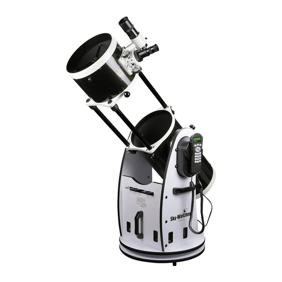
Summary of Contents for SKY-WATCHER DOBSONIAN SYNSCAN
- Page 1 INSTRUCTION MANUAL DOBSONIAN SYNSCAN - 8” 10” 12” 14” 16” 240412V1 180610V6-3.08...
- Page 2 – – – – – – – – – – – – – – – – – – – – – – – – – – – – – – – – – POWER REQUIREMENTS POWERING THE DOBSONIAN SYNSCAN – – – – – – – – – – – – – – – – – – – – – – – – –...
- Page 3 DOBSONIAN BASE ASSEMBLY PARTS 8” and 10” 12” 14” and 16” Round base assembly Right side panel assembly Left side panel assembly Front panel Eyepiece holder / Countersunk head Phillips screws 1pc / 3pcs 1pc / 3pcs 1pc / 3pcs Feet / Countersunk head Phillips screws (silver) 3pcs / 3pcs 3pcs / 3pcs...
- Page 4 8”, 10”, and 12” Flip the round base assembly over. Attach the feet onto the assembly using the Countersunk head Phillips screws provided. Foot Round base assembly (the bottom side) Right side panel (12”) Reinforce board (8” and 10”) Handle Hex socket flat head screw 7x50 Right side panel assembly Left side panel...
- Page 5 (12”) (8” and 10”) Right side panel assembly Right side panel assembly Hex socket head cap Hex socket head cap screw M5x60 screw M5x60 Large washer for Large washer for M5 screw M5 screw Azimuth Motor box Azimuth Motor box (12”) (8”...
- Page 6 14”and 16” ide and front panel setup eft side panel Locate the hand control holder. Right side panel Reinforce board Using the two screws provided , attach the holder to the Left side panel assembly Reinforce board Hex socket flat head screw 7X50 Left side panel ount setup assembly...
-
Page 7: Primary Mirror Installation
PRIMARY MIRROR INSTALLATION 1. When installing the mirror into the optical tube, you Fig.1 must first remove the rear end ring attached to the lower section of the optical tube. Simply unthread and remove the eight Phillips-head screws that connect the end ring to the tube (Figure 1), and then pull the end ring off of the tube. - Page 8 Fig.3 Figure 3. Find the area of tube that is bulg- ing out and obstructing it from seating in the end ring. Press on the bulge to force the tube into the end ring. 3. It can be a tricky task when assembling the end ring (and mirror cell) back onto the tube. The complication is that the large diameter and thin metal of the tube will cause the tube to become somewhat out of round once the end ring is removed.
-
Page 9: Telescope Setup
TELESCOPE SETUP Place the mount on the ground. Place a bubble level on the top of the round base to ensure the mount is set on a leveled plane. Better leveling will yield better tracking performance. To extend the telescope tube, loosen the three slider lock screws and pull the top part of the telescope assembly out until it clicks in place Tighten the slider lock screws. - Page 10 Altitude motor box Power supply cable: The Dobsonian SynScan requires 12-Volts DC Nominal power. The power cable from the battery pack or other power supply goes into the jack labeled Power on the altitude motor box. (Fig.a). Fig.a To avoid tangling of the power cable, the battery pack or power tank can be placed on the round base, behind the front panel.
- Page 11 AZ is a precision-engineered instrument that provides two different operation modes: AUTO-TRACKING MODE The Sky-Watcher Dobsonian SynScan telescope has a patented dual encoder design incorporated to record the position of the telescope. Under the Auto-Tracking Mode, you may choose to manually, or electronically, move the telescope to any position without deactivating the tracking mode first.
-
Page 12: Mode Keys
Mode keys Fig.f The mode keys are located near the top, close to the LCD display. They include the ESC, Display screen ENTER, and SETUP keys: ESC key is used to escape from a certain command or to go back a level in the menu tree. Mode keys SETUP ENTER... - Page 13 AUTOTRACKING OPERATION Fig.h Make sure that the telescope is set on a level ground. Point the telescope to the North. NORTH Locate the altitude scale on the inside of the left side board. Lower the telescope tube in altitude until it reads 0.
- Page 14 AZ GOTO OPERATION Make sure the mount is level to the ground. Point the telescope roughly to the brightest star in the sky to your naked eyes. Connect the hand control to the mount with the provided cable. Plug the DC 12 volt power into the outlet of the mount to turn on the power.
-
Page 15: Brightest Star Alignment
Brightest Star Alignment This alignment method is the most suitable if you are unfamiliar with the night sky, or are unsure of the name of the brighter stars. Find a visible single bright star that is far apart from any object in the sky. Point the telescope roughly to the star. -
Page 16: Two-Star Alignment
Two-Star Alignment The two star alignment procedure is similar to the Brightest Star alignment, except that the hand control will not prompt for you to select a directional region for a bright star. Below describes a step-by-step procedure on how to perform the Two-Star Alignment: In the alignment screen, select 2-Star Align using the scroll keys. - Page 17 3. After slewing to the object, press ESC to exit from the object catalog. Press the Utility button to enter to the Utility menu. Choose PAE under the utility menu and press ENTER. The SynScan hand control provides a short cut to quickly activate the PAE function. After exiting from the object catalog, instead of using the Utility menu, press and hold down the ESC key for 2 seconds.
- Page 18 The SynScan AZ comes with a vast database with over 42,900 objects coordinates and information all available in the palm of your hand. The database contains the following catalogs: Solar System - The other 8 planets of our solar system, plus the Moon. Named Star - A list of 212 best known stars from the SynScan AZ database.
- Page 19 Utility Functions are useful tools that provide simple, one-step processes to your SynScan Show Position - This displays the coordinates of the location where the telescope is currently pointed. The coordinates can be displayed in Dec and RA, Alt and Azm, or Ax1 (the angular reading of the elevation) and Ax2 (the azimuth axes of the mount).
- Page 20 RIGHT directional key to move the cursor to the next digit. First set the value for R.A. Press ENTER to proceed to Dec. Tracking Sid. Rate: This activates tracking in Sidereal rate (Dual Axes Tracking). Lunar Rate: This activates tracking in Lunar rate (Dual Axes Tracking). Solar Rate: This activates tracking in Solar rate (Dual Axes Tracking).
- Page 21 Fig.l The SynScan™ AZ hand control will display the coordinates where the telescope is currently pointed at in your desired format. See Fig.l for an example of the RA-Dec readout. If this is the location you would like to Enter RA-DEC: save, simply press ENTER to record the coordinates.
-
Page 22: System Requirements
Do not use RS-232 cable other than the one provided to connect RJ-11 Pin-outs between the hand control and your computer. It may damage your 1= EXPD+ 2= TD computer or the hand control. If you are making your own cable based 3= GND on the information provided in Appendix B, make sure that only pin 2, 3 4= EXPD-... - Page 23 Fig.q Fig.r SynScan Firmware Loader SynScan Firmware Loader Ver. 3.0 SynScan Update Ver. 1.7 Firmware File: Browse Enforce database update COM 1 Auto-detect COM Port COM Port SETUP ENTER Update Update HC. Version Click "Browse" to select the SynScanVXXXXAZ.ssf file in the SynScan folder. Click "Update"...
- Page 24 MAIN MENU TOUR SETUP MODE UTILITY FUNC. IDENTIFY Date Named Star Show Position Time Solar System Show Information Observ. Site Time Mercury Version Venus Daylight Saving Temperature Mars Alignment Power Voltage Jupiter Brightest Star Saturn Park Scope Align. Uranus 2-Star Align Neptune Clear PAE Data Pluto...
- Page 25 SynScan AZ SPECIFICATIONS Power Supply: 10 to 15 V DC 1Amp, 2.1mm Plug (Center positive) Motor type: DC Servo Motors Slew speeds: Rate 0 = 1.0X Rate 1 = 2.0X Rate 2 = 8X Rate 3 = 16X Rate 4 = 32X Rate 5 = 200X Rate 6 = 400X Rate 7 = 600X...
- Page 26 The SynScan AZ telescopes are designed to receive control commands sent from a computer via the RS-232 port and RS-232 cable. Once connected, the SynScan AZ can be controlled by most popular planetarium software program. The SynScan AZ will communicate with the personal computer at 9600 bits/sec, no parity and stop bit.
- Page 27 Physical Connection Diagram RJ-11 Connector 1= NC 2= RD RD = 2 3= GND GND = 5 4= NC 5= TD TD = 3 6= NC The Back of the DB9 Pinout Sending a track rate through RS232 to the hand control Multiply the desired tracking rate (arc seconds /second) by 4.
- Page 29 NEVER USE YOUR TELESCOPE TO LOOK DIRECTLY AT THE SUN. PERMANENT EYE DAMAGE WILL RESULT. USE A PROPER SOLAR FILTER FOR VIEWING THE SUN. WHEN OBSERVING THE SUN, PLACE A DUST CAP OVER YOUR FINDERSCOPE TO PROTECT IT FROM EXPOSURE. NEVER USE AN EYEPIECE-TYPE SOLAR FILTER AND NEVER USE YOUR TELESCOPE TO PROJECT SUNLIGHT ONTO ANOTHER SURFACE, THE INTERNAL HEAT BUILD-UP WILL DAMAGE THE TELESCOPE OPTICAL ELEMENTS.
Need help?
Do you have a question about the DOBSONIAN SYNSCAN and is the answer not in the manual?
Questions and answers