Table of Contents
Advertisement
Advertisement
Chapters
Table of Contents

Related Manuals for SKY-WATCHER NEQ3


Summary of Contents for SKY-WATCHER NEQ3
- Page 1 INSTRUCTION MANUAL Telescopes with NEQ3 & EQ5 Mount 031007V3...
- Page 2 REFRACTOR NEQ3 (150mm/1200mm) EQ3-2 Dust Cap/Mask Dust Cap/Mask (Remove before Viewing) (Remove before Viewing) Sun Shade Sun Shade Objective Lens Objective Lens Telescope Main Body Telescope Main Body Piggyback Bracket Piggyback Bracket Finderscope Finderscope Finderscope Bracket Finderscope Bracket Alignment Screw...
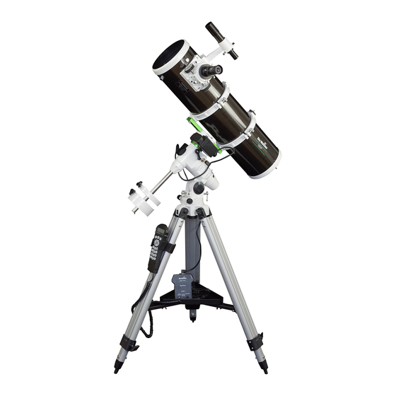
- Page 3 REFLECTOR NEQ3 (200mm/1000mm) EQ3-2 Dust Cap/Mask Dust Cap/Mask (Remove before Viewing) (Remove before Viewing) Focus Tube Focus Tube Finderscope Finderscope Finderscope Bracket Finderscope Bracket Finderscope Adjustment Finderscope Adjustment Screws Screws Eyepiece Eyepiece Focus Knob Focus Knob Piggyback Bracket Piggyback Bracket...
- Page 4 MAKSUTOV NEQ3 Dust Cap (not shown, remove before Viewing) Red Dot Finder Focus Locking Screw Eyepiece Diagonal Focusing Knob R.A Lock Knob Dec Flexible Control Cable Polarscope Holder/ Polarscope (not shown, optional) Altitude Adjustment T-bolt Azimuth Adjustment Knobs Counterweight Locking...
-
Page 5: Table Of Contents
Eyepiece Assembly Operating Your Telescope Aligning the Finderscope Using the Red Dot Finder Balancing the telescope Using the leveling bubble Operating the NEQ3 Mount Operating the EQ5 Mount Using the Barlow Lens Focusing Polar Alignment for visual use Pointing your telescope... -
Page 6: For Neq3
FOR NEQ3 MOUNT TRIPOD SET UP Fig. 2 ADJUSTING THE TRIPOD LEGS (Fig.18) Fig. 1 1) Slowly loosen the height adjustment clamp and gently pull out the lower section of each tripod leg. Tighten the clamps to hold the legs in place. -
Page 7: Finderscope/Red Dot Finder Assembly
TELESCOPE ASSEMBLY ATTACHING THE TUBE RINGS TO THE MOUNT (Fig.9) 1) Remove the telescope tube assembly from Fig.9 its plastic packaging. 2) Remove the tube rings from the telescope by releasing their thumb nuts and opening their hinges. 3) Using the bolts provided, fasten the tube rings to the mount with the 10mm wrench provided. -
Page 8: For Eq5
FOR EQ5 MOUNT TRIPOD SET UP ADJUSTING THE TRIPOD LEGS (Fig.18) Fig.19 Fig.18 1) Slowly loosen the height adjustment clamp gently pull out the lower section of each tripod leg. Tighten the clamps to hold the legs in place. 2) Spread the legs apart to stand the tripod upright. 3) Adjust the height of each tripod leg until the tripod head is properly leveled. -
Page 9: Finderscope Assembly
TELESCOPE ASSEMBLY ATTACHING THE TUBE RINGS TO THE MOUNT(Fig.25) 1) Remove the telescope tube assembly Fig.25 from its plastic packaging. 2) Remove the tube rings from the telescope by releasing their thumb nuts and opening their hinges. 3) Using the bolts provided, fasten the tube rings to the mount with the 10mm wrench provided. -
Page 10: Operating Your Telescope
OPERATING YOUR TELESCOPE The finderscope (optical or red dot) is a very useful accessory that is included with your telescope. When the finderscope is correctly aligned with the telescope, objects can be quickly Fig.a located and brought to the centre of the field. Alignment is best done outdoors in day light when it's easier to locate objects. - Page 11 A Telescope should be balanced before each observing session. Balancing reduces stress on the telescope mount and allows precise control of micro-adjustment. A balanced telescope is specially critical when using the optional clock drive for astrophotography. The telescope should be balanced after all accessories (eyepiece, camera, etc.) have been attached.
- Page 12 Fig.e The NEQ3 mount has controls for both conventional altitude (up-down) and azimuth (left-right) directions of motion. These two adjustments are suggested for large direction changes and for terrestrial viewing. The two Azimuth azimuth adjustment knobs located near the tripod head...
- Page 13 Fig.g Eyepiece Barlow A Barlow is a negative lens which increases the Diagonal magnifying power of an eyepiece, while reducing the field of view. It expands the cone of the focussed light before it reaches the focal point, so that the telescope's focal length appears longer to the eyepiece.
- Page 15 Fig.m You aim your telescope by rotating it along the RA and Dec axes of your mount. In the upper image the telescope is in the HOME position, aimed due north. The side images show the telescope pointing NE (right side) and SW (left side).
-
Page 16: Using The Setting Circles
Now it is time to learn what those numbered dials are for! Fig.n The dials are called setting circles and they can be used to help you find objects in the sky simply by dialing in a set of coordinates. All objects in the sky have assigned coordinates labeled Right Ascension (RA for short) and Declination (Dec for short). - Page 17 Vega has the coordinates RA 18h 37m. With Vega centered in your eyepiece loosen the RA setting circle setscrew and rotate the scale until it reads 18h 36m. (If you are in the Northern hemisphere use the top row of numbers.
- Page 18 Calculating the magnification (power) The magnification produced by a telescope is determined by the focal length of the eyepiece that is used with it. To determine a magnification for your telescope, divide its focal length by the focal length of the eyepieces you are going to use.
-
Page 19: Observing The Sky
OBSERVING THE SKY Sky conditions are usually defined by two atmospheric characteristics, seeing, or the steadiness of the air, and transparency, light scattering due to the amount of water vapour and particulate material in the air. When you observe the Moon and the planets, and they appear as though water is running over them, you probably have bad "seeing"... -
Page 20: Proper Care For Your Telescope
PROPER CARE FOR YOUR TELESCOPE Fig.q Collimation is the process of aligning the mirrors of your telescope so that they work in concert with each other to deliver properly focused light to your eyepiece. By observing out-of-focus star images, you can test Correctly aligned Needs collimation whether your telescope's optics are aligned. - Page 21 alternately loosen one and then compensate for the slack by tightening the other two. Stop when you see all three mirror clips (Fig.q-4). Make sure that all three small alignment screws are tightened to secure the secondary mirror in place. Aligning the Primary Mirror Find the three locking screws at the back of your telescope and loosen them by a few turns.
- Page 22 Collimation is the process of aligning the lenses of your telescope so that the light they collect will focus at the right spot Fig.r at the back of your telescope for your eyepieces to work. Collimation is a simple process and works like this: Pull off the dew cap at the front of your telescope and look into the scope.
- Page 23 APPENDIX A - PRECISE POLAR ALIGNMENT FOR NORTHERN HEMISPHERE When your equatorial mount is polar-aligned it is able track the sky easily and hold targets in the eyepiece with just occasional adjustments to the RA control cable. If your mount is motorized it can hold objects in the eyepiece almost indefinitely.
- Page 24 SIMPLIFIED POLAR ALIGNMENT PROCEDURES The NEQ3 and EQ5 mounts have specially designed reticule patterns and simplified procedures to make polar aligning your mount very simple. In fact, if you purchased a SynScan equipped mount you can perform an extremely accurate polar alignment in less than two minutes! See the SynScan User manual for details.
-
Page 25: Appendix B-Optional Accessories
HEQ5 or EQ6 mount. The NEQ3 and EQ5 SynScan mounts use the same Go-To system found in the HEQ5 and EQ6 Pro mounts. -
Page 26: Appendix C-Recommended Reading
APPENDIX C - RECOMMENDED READING Beginner's Guide to Amateur Astronomy: An The Great Atlas of the Stars by Serge Brunier, Owner's Manual for the Night Sky by David J. Constellation photography by Akira Fujii (Firefly Eicher and, Michael Emmerich (Kalmbach Books;... - Page 28 EQ3 SynScan INSTALLATION CONTENTS Power Cord Motor Cables Hand Control Cable Hand Control Hand Control Holder Fig.2 Fig.1 Hand Controller Auto Guide DC 12V Motor Controller holder Motor Controller SETTING UP Locate the hand control holder. Slide the holder onto the accessory tray as shown in Fig.1. Point the mount to the North, or South in the Southern Hemisphere.
- Page 29 INSTRUCTION MANUAL SynScan 140303V4 Copyright © Sky-Watcher...
- Page 30 CONTENT CONTENT Basic Operations PART VIII : AUXILIARY FUNCTIONS 8.1 Editing Date, Time, Coordinates, Time Zones, and Daylight Saving Time ..27 PART I : INTRODUCTION 8.2 Re-aligning the Mount ..................27 1.1 Outline and Interface ..................4 8.3 Show Position ....................27 1.2 Connecting to a Telescope Mount ..............
-
Page 31: Part I : Introduction
Connect the 8-pin (RJ-45) “Mount” port of the hand control to the “Hand Control” port on a tracking is turned on; it is not the axis’s rotation speed. Sky-Watcher mount using an appropriate cable. The table below lists the “Hand Control” ports Maximum speed varies on mounts. For most Sky-Watcher mounts, it is higher than 800X on different Sky-Watcher mounts. -
Page 32: Part Ii : Initialization
To operate the SynScan hand control in “Easy Tracking” mode, the mount should be setup as close to home position as possible, according to the following instuctions: In Easy Tracking mode, the hand control also needs to connect to a Sky-Watcher tele- •... - Page 33 ” is displayed, use the scroll keys to select “ ” or “ ”. “ ” This step only applies to a mount with Auto-homing feature (such as the Sky-Watcher EQ8 Equatorial mount). indicates the time entered in the previous step is daylight saving time, while “ ” indi- cates the time entered is in standard time.
-
Page 34: Part Iii : Alignment
PART III : ALIGNMENT PART III : ALIGNMENT Now users can use the direction keys to move the telescope to align with the 1 alignment 3.1 Choosing an Alignment Method star. That is, center the 1 alignment star in the FOV of the finder scope, and then center At the beginning of the alignment process, users are asked to choose an alignment method. - Page 35 PART III : ALIGNMENT PART III : ALIGNMENT Now the screen will display “ Point scope to RR ZZ.Z’ TT.T’ ”, which means point the telescope N (0˚) to RR region, the exact azimuth is ZZ.Z degree and the exact altitude is TT.T degree. Users can use the direction keys on the SynScan hand control to move the mount and point the (315˚) (45˚)
-
Page 36: Alt-Azimuth Mounts Using 2-Star Alignment Method
PART III : ALIGNMENT PART III : ALIGNMENT 3.5 Alt-Azimuth Mounts using 2-Star Alignment Method 3.6 Tips for Improving Alignment Accuracy Aligning the 1 Star: Eyepiece Choose 1 Star The LCD screen displays “ ” in the first line. Use the scrolling keys to browse It is very important to put the alignment stars at the center (or the same spot) of the FOV of the through a list of star names and Press ENTER... -
Page 37: Part Iv : Synscan Menu Tree
PART III : ALIGNMENT PART IV : SYNSCAN MENU TREE Equatorial Mount with 2-Star Alignment: 4.1 Menu Structure Advantage: For visual observing, the mount does not need to be polar-aligned accurately. The SynScan hand control uses menu tree to organize its various functions. The following Preconditions: Small cone error in the telescope-mount setup. -
Page 38: Accessing Menus
PART V : LOCATING OBJECTS PART IV: SYNSCAN MENU TREE 4.2 Accessing Menus Users can access several popular celestial object catalogs stored in the SynScan hand control The SynScan hand control’s menu is only accessible after the initialization, or after the star and control the telescope mount to locate a specific object in the catalogs. -
Page 39: Locating Ngc And Ic Objects
PART V : LOCATING OBJECTS PART V : LOCATING OBJECTS 5.2 Locating NGC and IC Objects 5.5 Locating SAO Stars The process for locating NGC or IC objects is similar to that for locating Messier objects (Sec- Choosing an Object: tion 5.1), with the following differences: OBJECT OBJECT LIST... - Page 40 PART V : LOCATING OBJECTS PART V : LOCATING OBJECTS • If the “R.A.-Dec.” coordinates is chosen: The screen will display the coordinates to Locate the Object: which the telescope is pointing to at the moment. • The operation is similar to that of locating Messier objects; refer to Section 5.1 for de- •...
- Page 41 6.4 Enable/Disable Auxiliary Encoder the moving direction of an axis with opposite direction keys. Such backlash compensation Some Sky-Watcher’s mounts are equipped with auxiliary encoders on their primary axes to function helps the user get faster response from the mount.
- Page 42 PART VII : CONFIGURE THE HAND CONTROL PART VIII : AUXILIARY FUNCTIONS 7.1 Display and Keypad 8.1 Editing Date, Time, Coordinates, Time Zones, and Daylight Saving Time MENU Access the menu “ Setup \ Handset Setting ” and press the ENTER key.
- Page 43 8.9 Changing Polar Scope Illumination Level Providing the base of the mount is not moved, users can recover the pointing accuracy with This function applies only to certain Sky-Watcher’s equatorial mounts that are equipped with the “ Synchronize Encoder ”...
- Page 44 PART IX : CONNECTING TO A COMPUTER PART X : UPDATING FIRMWARE 10.1 Hardware Requirements 9.1 Working with Astronomical Applications A SynScan hand control with firmware version 3.0 or above. After the SynScan hand control is initialized, it can communicate with a computer via the RS- 232C connection on its multi-purpose port.
-
Page 45: Part Xi : Advanced Functions
PART XI : ADVANCED FUNCTIONS PART X : UPDATING FIRMWARE • Check the “ Auto-detect COM port ” to let the application detect the proper serial port that 11.1 Parking Telescope will connect to the SynScan hand control. Clear it to manually choose the COM Port COM port If the mount of the telescope have not been moved after an observing session, the user can and select a serial port from the “... -
Page 46: Polar Alignment Without Polar Scope
PART XI : ADVANCED FUNCTIONS PART XI : ADVANCED FUNCTIONS The SynScan hand control divides the sky into 85 small zones, and users can calibrate the 11.3 Polar Alignment without Polar Scope pointing error for each of these zones. The next time that the SynScan controller tries to The polar alignment function can help users to polar align an equatorial mount accurately. -
Page 47: Camera Control
Using the SNAP port on the telescope mount: Set the camera to bulb exposure mode. Several Sky-Watcher’s equatorial mounts (such as the AZ-EQ6 GT and the EQ8) are equipped with a SNAP port. Users can use a proper shutter release control cable to con- Press the “... -
Page 48: Periodic Error Correction (Pec) For Eq Mount
PEC (SPEC), which applies to Sky-Watcher’s EQ3/EQ5/HEQ5/EQ6 Pro mount. 11.6 Calibrating Auto-Home Offset The other is permanent PEC (PPEC), which applies to Sky-Watcher’s AZ-EQ6 GT mount and Some Sky-Watcher’s equatorial mounts (ex. the EQ 8 mount) has the Auto-Home function EQ8 mount. -
Page 49: Part Xii : Using A Synscan Gps Module
APPENDIX I : ELIMINATING CONE ERROR PART XII : USING A SYNSCAN GPS MODULE Users may purchase a SynScan GPS module to acquire accurate local geographical coordi- If the telescope’s optical axis is not perpendicular to the declination axis of the equatorial nates and local time;... -
Page 50: Appendix 3
APPENDIX II : SYNSCAN SELF-DIAGNOSIS APPENDIX III : SCHEMATIC OF THE PORTS The SynScan hand control contains a built-in self-diagnosis program. To run a full test, users should prepare a “Loop-Test Plug” by referring to and the following instructions: Appendix 3 Vpp+ Vpp+ •... - Page 51 SynScan...
Need help?
Do you have a question about the NEQ3 and is the answer not in the manual?
Questions and answers