Honeywell GSMV4G Quick Installation Manual
Gsm communicators
Hide thumbs
Also See for GSMV4G:
- Installation and setup manual (64 pages) ,
- Quick installation manual (2 pages) ,
- Quick installation manual (2 pages)
Table of Contents
Advertisement
Quick Links
GSMV4G / GSMVCN4G, and IGSMV4G / IGSMVCN4G GSM Communicators – Quick Installation Guide
For Online Support visit: http://www.security.honeywell.com/hsc/resources/MyWebTech/
General Information and Component Identification
Congratulations on your purchase of Honeywell's GSMV4G or IGSMV4G communicator
(GSMVCN4G, and IGSMVCN4G in Canada). These communicators send alarms and
messages from the security system's control panel to AlarmNet for subsequent transfer
to the central monitoring station.
In addition to alarm reporting, they provide two-way voice communications with the
central station (when used with Honeywell's AVS Audio Verification System). They also
provide upload/downloading capability of Honeywell's control panel programming data.
Installation and Setup Guide
Refer to the
NOTE: Two-way voice is not compatible with Honeywell Commercial Control Panels
(such as the VISTA-128/250 series).
UL / ULC
Two-way voice has not been evaluated by UL / ULC.
The IGSMV4G communicator has all of the features of the GSMV4G and adds internet
connectivity. (For Canada, the GSMVCN4G and the IGSMVCN4G are designed to comply
with Canadian GSM connectivity specifications.) These communicators represent the
most innovative communication technology for the security industry and use
sophisticated encryption to ensure the highest level of security.
Since this guide covers both models, where differences occur they will be noted. This
guide addresses a simple installation using default programming values where possible
and is applicable for the majority of installations. For detailed information on UL, ULC,
and configuration of remote services, please refer to the appropriate
Setup Guide
for the product. The GSMV4G and the IGSMV4G are henceforth referred to
as the communicator or communications module.
• The communicator requires an AlarmNet account. For new installations, please
obtain the account information from the central station prior to programming.
• The communicator is for control panels that support GSM or IGSM communicators
and the ECP communications bus. For control panels that do not support ECP, refer
to the appropriate installation guide to use other communicator modes.
• The control panel treats the communicator as an ECP device, so ensure to program
the control panel with the communicator's device address. Refer to the control
Installation and Setup Guide
panel's
REMOTE SERVICES
Honeywell offers secure web based services that enable users to remotely monitor and
control their security system. These web services enable users to; monitor and control
their security system from a website or smartphone, receive email notifications of
system events, and receive event confirmations.
1. Determine Signal Strength and Select a Location
The communicator must be mounted indoors. When choosing a suitable mounting location,
understand that signal strength is very important for proper operation. For most installations
using the internal antenna, mounting the unit as high as practical, and avoiding large metal
components provides adequate signal strength for proper operation.
In this step, you will use the communicator to determine signal strength in order to find a
suitable mounting location.
Note: If the SIM is already activated, the RSSI signal strength indicators will indicate
signal strength. (The SIM in the GSMVCN4G and IGSMVCN4G is already activated.)
If the SIM has not been activated, the firmware in the communicator enables it to com-
municate with the cellular network towers (without the SIM being activated) so that
signal strength measurements can be determined. In this case, you can display the
signal strength by simultaneously pressing the TAMPER and MODE switches.
Allow at least 60 seconds for a reading to establish.
2. Mount and Wire the Communicator
1. Locate the case back over the selected mounting position such that the opening in the case
back is aligned with the wire/cable opening on the mounting surface.
2. Pass the wires/cable through the opening in the case back, or route through the removable
side knockouts located on the back cover. Then secure the case back to the mounting
surface using four screws (supplied). Make the following connections:
Distance from
Minimum
Control Panel
Wire Gauge
75 ft (23m)
#22
120 ft (37m)
#20
3. When all wiring has been completed (including the Internet cable if used), attach the case
front. Position the top first, then press the bottom section until it snaps in place. Secure
bottom using the supplied cover screw. (Required for UL installations.)
4. You may power up the communicator and control panel.
3. Connect the Internet Cable (IGSMV4G / IGSMVCN4G only)
Connect one end of the Ethernet cable (Category 5) to the communicator's RJ45 Ethernet
connector and the other end to the cable/DSL router as shown in the figure.
• For UL installations, the Ethernet connection between the communicator and
the router cannot exceed 12 feet. Both units must be located within the
UL
same room.
• Use a Listed cable/DSL router suited for the application.
for the use of these features.
Installation and
for details.
Distance from
Minimum
Control Panel
Wire Gauge
170 ft (52m)
#18
270 ft (82m)
#16
Dealers can enroll their customers for "Remote Services" by using the AlarmNet Direct website. Once
enabled, the specific programming fields associated with these features can be programmed into the
communications device either remotely using the AlarmNet Direct website or locally using the 7720P
programming tool.
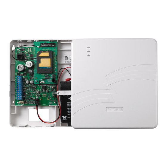
Due to Honeywell's continuing effort to improve our products, your device may look slightly different than
pictured.
For internet models only.
POWER LOADING SPECIFICATIONS
GSMV4G / GSMVCN4G: 65mA standby, 380mA active.
IGSMV4G / IGSMVCN4G: 65mA standby, 380mA active.
Note: Read and follow the RF Exposure notice on the other side.
1. Unpack the communicator and open the case by pushing in the two bottom tabs with a
screwdriver while separating the case front.
2. Temporarily connect the AC transformer or battery to the communicator.
3. Choose the installation site with the best signal strength by
observing the signal strength (RSSI) bar graph. Signal
strength should be within 3-5 bars. The best signal strength is
usually found at the highest point in the building, near a
window.
4. Mark the location for the communicator.
Advertisement
Table of Contents

Related Manuals for Honeywell GSMV4G


Summary of Contents for Honeywell GSMV4G
- Page 1 AlarmNet Direct website or locally using the 7720P to the central monitoring station. programming tool. Due to Honeywell's continuing effort to improve our products, your device may look slightly different than In addition to alarm reporting, they provide two-way voice communications with the pictured.
- Page 2 The communicator requires an optional audio cable (GSMV-AUDIO, grey) to support two-way voice using an AVS Base Unit. Note the AVS Base Unit is part of Honeywell’s AVS Audio Verification System. This system consist of the AVS Base Unit, Remote Station, and the Remote Station PC board.
Need help?
Do you have a question about the GSMV4G and is the answer not in the manual?
Questions and answers