Table of Contents
Advertisement
Quick Links
Download this manual
See also:
Owner's Manual
Advertisement
Table of Contents

Related Manuals for CPS AC750


Summary of Contents for CPS AC750
- Page 1 AC750 DIGITAL CLAMP METER Operation Manual AC750...
-
Page 2: Table Of Contents
CONTENTS 1. Safety Information ........1.1 Preparation ..........1.2 Usage ............1.3 Mark ............1.4 Maintenance ........... 2. Description ........... 2.1 Part Name ..........2.2 Switch and Button Description ....2.3 LCD Display ..........3 Specification ..........3.1 General ............ 3.2 Technique Data ........ - Page 3 CONTENTS 4.10 Current Measurement ......4.11 Voltage Measurement ......4.12 Frequency And Duty Ratio Measurement ......4.13 Resistance Measurement ....... 4.14 Diode Test ..........4.15 Circuit Continuity Test ......4.16 Capacitance Measurement ..... 4.17 Surge Current Measurement ....4.18 Non-Contact Voltage Detection ....5 Maintenance ...........
-
Page 4: Safety Information
1. Safety Information Please particularly note that inappropriate use may cause shock or damage to the meter when using. When using the meter, comply with common safety procedures and complete- ly follow the safety measures stated in the operation manual. In order to make full use of the meter’s functions and ensure safe operation, please carefully read and follow the proce- dures in the operation manual. -
Page 5: Usage
1.2 Usage 1.2.1 When using the meter, select the right function and measuring range. 1.2.2 Don’t make measurements that exceed indicated values in each measuring range. 1.2.3 When measuring circuits with the meter connected, do not contact with probe tip (metal part). 1.2.4 If voltage to be measured is more than 60V DC or 30V AC (RMS), always keep your fingers behind finger protection device. -
Page 6: Mark
1.3 Mark Note (Important safety information. Refer to the operation manual) Dangerous electric conductor Double insulation protection (class II) According to pulse voltage tolerance protection level provided by IEC 61010-1 standard overvoltage (installation) level III and pollution degree 2. The meter complies with EU standard Grounding This product has been tested to the requirements of CAN/CSA-C22.2 No. -
Page 7: Maintenance
1.4 Maintenence 1.4.1 Don’t try to open the meter bottom case to adjust or repair. Such operations only can be made by technicians who fully understand the meter and electrical shock hazard. 1.4.2 Before opening the meter bottom case or battery cover, remove probe from the circuit to be measured. -
Page 8: Part Name
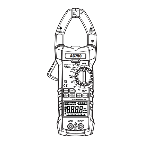
2.1 Part Name (1) Non-contact voltage detection sensing area (2) Current clamp head: used for current measurement. (3) Clamp head light (4) Rotary switch (5) Input Socket (6) NCV indicator (7) Trigger (8) Key (9) Display (10) USB Port Pg 05... - Page 9 AC750 Pg 06...
-
Page 10: Switch And Button Description
2.2 Rotary Switch, Button And Input Jack Description B.L/RANGE button: used for measuring range switch or back light control. FUNC button: used for measuring function switch. HOLD button: data hold. REL/ZERO button: Used for entering relative measurement state (when making non-DC current measurement), DC current zeroing function (DC current measurement). - Page 11 AC, DC Alternating Current, direct current Diode, on/off AUTO Automatic measuring range mode MAX /MIN Maximum/minimum measurement Surge current test Relative measurement mode Automatic power-off indicator DC current zeroing function LOW BATTERY Reading hold state Percentage (duty ratio) mV,V,A Millivolt, Volt (voltage), Ampere (current) nF,μF,mF Nano farad, Microfarad, Millifarad Ohm, Kilohm, Megohm (resistance)
-
Page 12: Specification
3. Specifications Each year, the meter should be recalibrated at 18°C ~ 28°C < 75%. 3.1 General • Automatic measuring range and manual measuring range. • Full measuring range overload protection. • The maximum allowable voltage between measurement end and ground: 1000V DC or 750V AC •... -
Page 13: Technique Data
3.2 Technical Indicators 3.2.1 True RMS Zero Input Characteristic 3.2.1.1 For measuring non-sinusoidal wave signals, use the true RMS measuring method, which has less error than the traditional average response measuring method. 3.2.1.2 The true RMS meter can accurately measure non-sinusoidal wave signals, but in AC function when there is no signal to be measured, the clamp meter may show a reading from 1 to 50. - Page 14 3.2.3 DC Current Measuring range Resolution Accuracy 0.01A 600A 0.1A ±(2.5% reading + 8 digits) 1000A - Maximum input current: 1000A DC 3.2.4 Surge Current Measuring range Resolution Accuracy 0.01A < 60A for reference only 600A 0.1A ±(10% reading + 60 digits) 1000A Time of integration: 100ms;...
- Page 15 - Input impedance: 10MΩ - Maximum input voltage: 750V AC (RMS) or 1000V DC - 600mV measuring range can be inputted only by RANGE key. Note: In the small voltage measuring range, the probe is not connected with the circuit to be tested, and the meter may have fluctuating readings, This is normal and caused by the meter’s high sensitivity, and does not affect actual measurement results.
- Page 16 3.2.7 Frequency 3.2.7.1 Clamp head measuring frequency (through range A): Measuring range Resolution Accuracy 60.00Hz 0.01Hz 600.0Hz 0.1Hz ±(1.5% reading + 5 digits) 6.000kHz - Measuring scope: 10Hz~1kHz - The input signal range: 20A AC (RMS) (input current will increase when the frequency to be measured increases) 3.2.7.2 Through grade V: Measuring range...
- Page 17 3.2.7.3 Through Hz grade: Measuring range Resolution Accuracy 60.00Hz 0.01Hz 600.0Hz 0.1Hz 6.000kHz 60.00kHz 0.01kHz ±(0.3% reading + 5 digits) 600.0kHZ 0.1kHZ 6.000MHZ 1kHZ 60.00MHZ 0.01MHZ - The input signal: VPP 3V square wave; Overload protection: 250V DC or AC (RMS) 3.2.8 Duty Ratio Measuring range Resolution...
- Page 18 3.2.10 Circuit Continuity Test Measuring range Resolution Function If the resistance of circuit to be measured is less than 0.1Ω 50Ω, the meter’s built-in buzzer may sound. - Overload protection: 250V DC or AC (RMS) 3.2.11 Capacitance Measuring range Resolution Accuracy 6.000nF 0.001nF...
-
Page 19: Operation
4. Operation 4.1 Reading Hold In the process of measurement, if reading hold is required, then press “HOLD” key to release reading hold. 4.2 Manual Measuring Range RANGE key is automatic/manual measuring range key to trigger mode. The preset function is automatic measuring range. Press to switch to manual measuring range. -
Page 20: Maximum/Minimum Measurement Choice
4.4 Maximum/Minimum Measurement Choice 1) Press “MAX/MIN” key to enter MAX mode and save measurement maximum value. Press “MAX/MIN” key again and the meter will enter minimum value measurement state and save minimum value. 2) After entering MAX or MIN mode, the meter will automatically save the measured maximum or minimum value. -
Page 21: Surge Measurement
4.7 INRUSH Measurement In the AC current measurement state, press INRUSH key to enter surge measurement state, then press INRUSH key again to quit surge measurement state. 4.8 Automatic Power-Off 1) If there is no operation for 10 minutes (5 minutes when measuring current) after turning the machine on, the meter will enter a suspended state, automatically powering off to save the batter. -
Page 22: Current Measurement
4.10 Current Measurement 1) Rotary switch is placed to position A. At this time, the meter is in AC current measurement state. Choose appropriate measuring range. If you want to measure DC current, press FUNC button to enter direct current measurement state. 2) Hold the trigger, open clamp head, clip one lead of measurement circuit to be tested in the clamp. -
Page 23: Voltage Measurement
4.11 Voltage Measurement 1) Insert black probe to COM jack, insert red probe to INPUT jack, choose appropriate measuring range. 2) Place rotary switch to AC voltage position. At this time, the meter is in the AC voltage measurement state. To measure DC voltage, press FUNC button to enter DC voltage measurement state. -
Page 24: Resistance Measurement
4.13 Resistance Test 1) Insert black probe to COM jack, insert red probe to INPUT jack. 2) Place measuring range switch to Ω position. At this time, the meter is in the measurement state. 3) Connect the probe to the both ends of resistor or circuit to be tested. 4) LCD will show readings. -
Page 25: Circuit Continuity Test
4.15 Circuit Continuity Test 1) Insert black probe to COM jack, insert red probe to INPUT jack. 2) Measuring switch is placed to position Ω 3) Press “FUNC” key to switch to circuit continuity measuring state. 4) Connect the probe to the both ends of circuit to be tested . 5) If the resistance of circuit to be measured is less than 30Ω, the meter’s built-in buzzer may sound. -
Page 26: Non-Contact Voltage Detection
Note: 1) Clamping two or more leads of circuit to be tested simultaneously will not give correct readings. 2) To get accurate reading, connect the lead to be tested at the center of current clamp. 3) In the manual measuring range mode, when LCD only shows “OL”, which indicates over-range, choose higher measuring range. -
Page 27: Maintenance
5. Maintenance 5.1 Replace Battery Warning TO AVOID ELECTRICAL SHOCK, REMOVE TEST LEADS BEFORE OPENING BATTERY COVER. 1) When the battery indicator “ ” appears, the battery should be replaced immediately. 2) Unscrew the fastening screw of the meter battery cover and remove it . 3) Replace battery. -
Page 28: Attachments
6. Accessories The AC750 comes with the following items • AC750 AC/DC Clamp Meter • Carrying Case • 9V Battery • 1000V, 10A Probe Set • USB Communication Cable • Software (on CD) Pg 25... - Page 29 All repaired equipment will carry an independent 90-day warranty. This repair policy does not include equipment that is determined to be beyond economical repair. CPS Products, Inc. CPS Products, Inc. U.S.A. (Headquarters) 1010 East 31st Street, Hialeah, Florida 33013, USA Tel: 305-687-4121, 1-800-277-3808, Fax: 305-687-3743 E-mail: info@cpsproducts.com www.cpsproducts.com...
- Page 30 #AC750 MANUAL...
Need help?
Do you have a question about the AC750 and is the answer not in the manual?
Questions and answers