
Related Manuals for CPS AC750


Summary of Contents for CPS AC750
- Page 1 AC750 DIGITAL CLAMP METER OWNER’S MANUAL (English) Français, Español, Deutsch: www.cpsproducts.com...
-
Page 2: Table Of Contents
1.1 Preliminary ................1 1.2 Usage ..................2 1.3 Symbols ..................3 1.4 General Use ................4 2. Description 2.1 AC750 Layout ................5 2.2 Switch, Key and Input Jack Description ........6 2.3 LCD Display ................7-8 3. Specifications 3.1 General ..................9 3.2 Technical Data ..............10-15 4. - Page 3 CONTENTS 4.10 Current Measurement ............19 4.11 Voltage Measurement ............20 4.12 Frequency and Duty Ratio Measurement .......20 4.13 Resistance Measurement ............21 4.14 Diode Test ................21 4.15 Circuit Continuity Test ............22 4.16 Capacitance Measurement .............22 4.17 Surge Current Measurement ..........22 4.18 Non-Contact Voltage Detection ..........23 5.
-
Page 4: Safety Information
1. SAFETY INFORMATION WARNING BE EXTREMELY CAREFUL WHEN USING THIS METER. IMPROPER USE OF THIS DEVICE CAN RESULT IN ELECTRIC SHOCK OR DESTRUCTION OF THE METER. TAKE ALL NORMAL SAFETY PRECAUTIONS AND FOLLOW THE SAFEGUARDS SUGGESTED IN THIS MANUAL. TO EXPLOIT FULL FUNCTIONALITY OF THIS METER AND ENSURE SAFE OPERATION, PLEASE READ CAREFULLY AND FOLLOW THE DIRECTIONS IN THIS MANUAL. -
Page 5: Usage
1. SAFETY INFORMATION 1.2 USAGE 1.2.1 DO NOT measure voltage greater than 750 V AC, 1000 V DC. 1.2.2 DO NOT measure resistor, capacitor, diode and circuit while connected to power. 1.2.3 DO NOT measure capacitance before capacitor is discharged completely. - Page 6 1. SAFETY INFORMATION Note-Important safety information, refer to the instruction manual. Application around and removal from UNINSULATED HAZARDOUS LIVE conductors is permitted. Caution, possibility of electric shock Equipment protected throughout by double insulation or reinforced insulation. Conforms to UL STD. 61010-1, 61010-2-032, 61010-2- 033;...
-
Page 7: General Use
1. SAFETY INFORMATION 1.4 GENERAL USE 1.4.1 Do not open case to adjust or repair (only for technicians who fully understand this meter and electrical shock hazard). 1.4.2 Before opening case or battery cover, remove probe from circuit to be measured. -
Page 8: Ac750 Layout
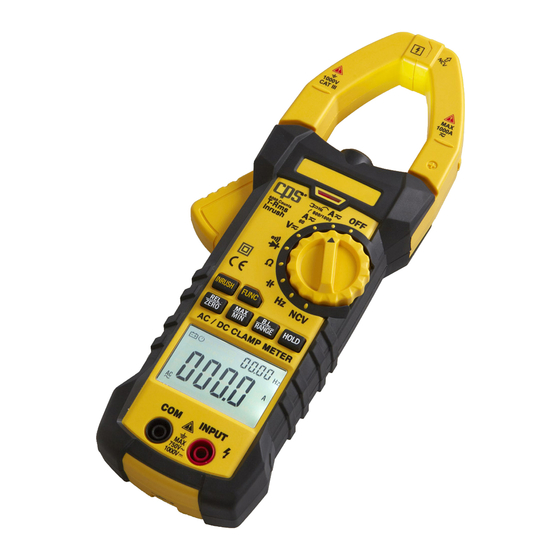
2. DESCRIPTION 2.1 AC750 LAYOUT 1. Current clamp head (for current measurement) 2. Clamp head light 3. Control panel 4. Jaw Trigger 5. Function choice key (FUNC) 6. Relative measurement key 7. Frequency/duty ratio switch key (Hz/%) 8. LCD display 9. -
Page 9: Switch, Key And Input Jack Description
2. DESCRIPTION 2.2 SWITCH, KEY AND INPUT JACK DESCRIPTION BL/HOLD Back light or reading hold key FUNC Function key (use with Selector Switch) RANGE For switching manual measuring range state For entering relative measurement state Hz/% For frequency and duty ratio measurement function switch MAX/MIN For maximum/minimum measurement function switch For turning power OFF... -
Page 10: Lcd Display
2. DESCRIPTION 2.3 LCD DISPLAY Automatic power-off indicator AUTO Automatic measuring range mode Surge current test Diode, on/off Relative measurement mode MAX /MIN Maximum/minimum measurement Non-contact voltage detector Ω,kΩ,MΩ Ohm, Kilohm, Megohm (resistance) nF,μF,mF Nano farad, Microfarad, Millifarad AC, DC Alternating current, direct current Reading hold state DC current zeroing function... -
Page 11: Specifications
3. SPECIFICATIONS 3.1 GENERAL Maximum Input Current 1000A AC; 1000A DC Maximum Input Voltage 750V AC (RMS); 1000V DC 6mV/600mV/6V/60V/600V/750V (+/- AC Volts 0.6% reading); 750V (+/-0.8% reading) 6mV/600mV/6V/60V/600V/1000V (+/- DC Volts 0.5% reading); 1000V (+/-0.8% reading) AC Amps 60/600/1000 (+/- 2% reading) DC Amps 60/600/1000 (+/- 2% reading) 600/6K/60K/600K/6M/60M (+/- 2%... - Page 12 3. SPECIFICATIONS 3.2.1 TRUE RMS ZERO INPUT CHARACTERISTIC 3.2.1.1 For measuring non-sinusoidal wave signals, use true RMS measuring method, which has less error than traditional average response measuring method. 3.2.1.2 This true RMS meter can accurately measure non-sinusoi- dal wave signals, but in AC function mode, when there is no signal to be measured (input terminal short circuit in AC voltage mode), clamp meter may show a reading from 1 to 50.
- Page 13 3. SPECIFICATIONS 3.2.3 DC CURRENT Measuring range Resolution Accuracy 0.01A 600A 0.1A ±(2.0% reading + 8 digits) 1000A • Maximum input current: 1000A DC 3.2.4 SURGE CURRENT Measuring range Resolution Accuracy 0.01A < 60A for reference only 600A 0.1A ±(5% reading + 60 digits) 1000A Time of integration: 100ms;...
- Page 14 3. SPECIFICATIONS 3.2.6 AC VOLTAGE Measuring range Resolution Accuracy 600mV 0.1mV 0.001V ±(0.8% reading + 5 digits) 0.01V 600V 0.1V 750V ±(0.8% reading + 4 digits) • Input impedance: 10M • Maximum input voltage: 750V AC (RMS) or 1000V DC •...
- Page 15 3. SPECIFICATIONS 3.2.7.3 Through mode HZ/DUTY: Measuring range Resolution Accuracy 9.999Hz 0.01Hz 99.99Hz 0.1Hz 999.9Hz 0.001kHz ±(0.3% reading + 5 digits) 9.999kHz 0.01kHz 99.99kHz 0.1kHz 999.9kHz 0.001MHz 9.999MHz 0.001kH • Overload protection: 250V DC or AC (RMS) • Input voltage range: 2V (input voltage will increase when the frequency to be measured increases) 3.2.8 Duty Ratio Measuring range...
- Page 16 3. SPECIFICATIONS 3.2.9 RESISTANCE Measuring range Resolution Accuracy 600Ω 0.1Ω 6kΩ 0.001kΩ ±(0.8% reading + 3 digits) 60kΩ 0.01kΩ 600kΩ 0.1kΩ 6MΩ 0.001MΩ ±(2.0% reading + 5 digits) 60MΩ 0.1MΩ • Open circuit voltage: about 0.4 V • Overload protection: 250 V DC or AC (RMS) 3.2.10 CIRCUIT CONTINUITY TEST Measuring range Resolution...
-
Page 17: Manual Measuring Range
3. SPECIFICATIONS 3.2.12 DIODE TEST Measuring Resolution Function range Display approximate diode 0.001V forward voltage value • Forward DC current is about 1mA • Backward DC voltage is about 3.3V • Overload protection: 250V DC or AC (RMS) 4.1 READING HOLD 1. -
Page 18: Inrush Measurement
4. OPERATING GUIDANCE Note: If meter is in maximum/minimum value measurement state, it can not switch to frequency, duty ratio measurement mode. 4.4 MAX/MIN MEASUREMENT CHOICE 1. Press “MAX/MIN” key to enter MAX mode, and always keep measurement maximum value; press “MAX/MIN” key again, to enter minimum value measurement state;... -
Page 19: Backlight And Clamp Head Light
4. OPERATING GUIDANCE 3. In AC current measurement state, press REL/INRUSH more than 2 seconds to enter surge measuring state. 4.7 BACKLIGHT AND CLAMP HEAD LIGHT 1. During measurement, if ambient light is too dark to read the display, press and hold “BL/HOLD” key to activate backlight. Backlight will automatically turn off after 30 seconds. -
Page 20: Measurement Preparation
4. OPERATING GUIDANCE 4.9 MEASUREMENT PREPARATION 1. Rotate the Selector Switch to turn on power. When battery voltage is low (about ≤ 7.2 V), LCD displays symbol. Replace battery. means that voltage or current should not be more than the specified value to protect internal line from damage. -
Page 21: Voltage Measurement
WARNING ELECTRIC SHOCK HAZARD. PAY SPECIAL ATTENTION TO AVOID SHOCK WHEN MEASURING HIGH VOLTAGE. DO NOT INPUT VOLTAGE MORE THAN AC750 RMS. 1. Insert black probe to COM jack, insert red probe to INPUT jack, choose appropriate measuring range. 2. Place Selector Switch to AC voltage V or mV position. At this time, meter is in the DC voltage measurement state. -
Page 22: Frequency And Duty Ratio Measurement
4. OPERATING GUIDANCE 4.12 FREQUENCY AND DUTY RATIO MEASUREMENT A) Clamp head measuring frequency (through AC current): WARNING ELECTRIC SHOCK HAZARD. REMOVE PROBE FROM METER BEFORE MEASURING WITH CURRENT CLAMP. 1. Set Selector Switch to position A . 2. Hold trigger, open clamp head, clip one lead of measurement circuit to be tested in the clamp. - Page 23 4. OPERATING GUIDANCE 4. Connect probe with signal or both ends of load in parallel for measurement. 5. VRead on LCD. 6. Pressing Hz/% again enters duty ratio measuring state. Note: 1. Frequency measurement range is 10Hz~1kHz When the frequency to be tested is less than 10Hz,the LCD will show 00.0 Measuring frequency higher than 10kHz is possible, but accuracy is not guaranteed.
-
Page 24: Diode Test
4. OPERATING GUIDANCE 4.13 RESISTANCE TEST WARNING ELECTRIC SHOCK HAZARD. WHEN MEASURING CIRCUIT IMPEDANCE, DETERMINE THAT THE POWER SUPPLY IS DISCONNECTED AND THE CAPACITOR IN THE CIRCUIT IS COMPLETELY DISCHARGED. 1. Insert black probe to COM jack, insert red probe to INPUT jack. -
Page 25: Circuit Continuity Test
4. OPERATING GUIDANCE 4.15 CIRCUIT CONTINUITY TEST WARNING ELECTRIC SHOCK HAZARD. WHEN MEASURING CIRCUIT CONTINUITY, DETERMINE THAT THE POWER SUPPLY IS DISCONNECTED AND THE CAPACITOR IN THE CIRCUIT IS COMPLETELY DISCHARGED. 1. Insert black probe to COM jack, insert red probe to INPUT jack. 2. -
Page 26: Surge Current Measurement
4. OPERATING GUIDANCE 4.17 SURGE CURRENT MEASUREMENT WARNING ELECTRIC SHOCK HAZARD. REMOVE THE PROBE FROM THE METER BEFORE MEASURING WITH CURRENT CLAMP. 4.10.1 Set Selector Switch to position A. 4.10.2 Hold trigger, open clamp head, clip one lead of measurement circuit to be tested in the clamp. 4.10.3 Press REL/INRUSH key more than 2 sec. -
Page 27: Non-Contact Voltage Detection
5. MAINTENANCE Note: 1. Even if no indication, voltage may exist still. Do not use non-contact voltage detector to judge whether there is voltage in the wire. Detection operation could be affected by socket design, insulation thickness, type and other factors. 2. -
Page 28: Accessories
DMXTL 1 pair WARRANTY CPS Products, Inc. guarantees that all products are free of manufacturing and material defects to the original owner for one year from the date of purchase. If the equipment should fail during the guarantee period it will be repaired or replaced (at our option) at no charge.
Need help?
Do you have a question about the AC750 and is the answer not in the manual?
Questions and answers