Table of Contents
Advertisement
Quick Links
I N s T A L L A T I O N
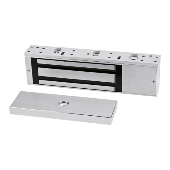
EML310/EML320
Electromagnetic Locks
Pre-Installation Instructions
1.
This product must be installed according to all applicable
building and life safety codes.
Due to the variety of mounting configurations available with
2.
this product, a survey and assessment of the physical area
in which the product will be installed must be performed.
3.
The door frame must be inspected and deemed structurally
sound prior to installation of the electromagnetic lock. The
structural integrity of the mounting surfaces must be strong
enough to meet or exceed the holding force of the product.
4.
The product must be protected from potential damage due
to intruders or tampering.
5.
The product should be installed in a location that will not
hinder or create a potential safety hazard to authorized
personnel accessing the protected area.
6.
Because electromagnetic locks are used in a variety of
applications and different door frame configurations, an
experienced installer with knowledge of this product must
make a determination of the optimal mounting method for
this specific application.
7.
The components, hardware, installation instructions and
mounting template included with this product are intended
for use on outswinging doors.
Mount the electromagnetic lock to the door frame as outlined
1.
on the installation template included with the product.
NOTE: During installation of the armature plate to the door it is
essential that the armature plate remains movable. The armature
plate must be allowed to pivot on the center-mounting bolt to
allow proper alignment with the magnet surface. If the plate is
not aligned with the magnet surface, the lock may lose holding
force or not lock at all.
The head of the armature mounting bolt ships with a rubber
washer affixed to it. this washer should project slightly beyond
the surface of the armature plate. This is to allow the washer
to expand when power is removed and break the air vacuum
between the plate and the magnet surface. If this washer is
removed or trimmed the lock will appear to have some holding
force even when power is removed.
ISEML310-20
08281600
uSa: DoRMa DRIvE, DRaWER aC, REaMStoWN, Pa 17567 PHoNE: (800) 523-8483 (717) 336-3881 faX: (717) 336-2106
PLEaSE DELIvER aLL INStaLLatIoN INStRuCtIoNS to
tHE END-uSER uPoN CoMPLEtIoN of tHE INStaLLatIoN.
8.
Do not install this product on the exterior of buildings.
9.
Do not use as a doorstop. This will void warranty.
10. Separate accessories not included with this product must be
used in the following applications:
Refer to the Product Accessories Guide section of
the Installation Instructions for further information.
Accessories may impact holding force.
11. Installation of this product should be done by an
experienced installer with knowledge of this product.
NOTE: It is highly recommended that thread locking compound
be applied to all screws during installation to reduce chance of
screws loosening over extended time.
Installation Instructions
for added safety, thread locking compound has been provided
for the armature plate bolt and the four captive electromagnetic
lock mounting screws. (See fig. 2 on page 2)
WARNING: Improper installation, maintenance, inspection or
usage of the product or any related accessories or parts may cause
the electromagnetic lock, armature plate and associated hardware
to disengage and fall, causing serious bodily injury and property
damage. Dorma will not be liable to the installer, purchaser, end
user or anyone else for damage or injury to person or property due
to improper installation, care, storage, handling, maintenance,
inspection, abuse, misuse or act of God or nature involving this
product or any related accessories or parts.
Route the power supply connecting wire through the door
2.
frame and into the wire access hole in the top of the magnet
housing. Connecting wire should be of sufficient gauge for the
lock being installed and the distance being run. See table on
page 8 for current draw specifications and wiring gauge chart.
© 2015 DoRMa
EMaIL: archdw@dorma-usa.com WEbSItE: dorma-usa.com
• Inswinging doors
• Narrow head jamb situations or center-hung doors
• Wherever there is insufficient space on the door
frame header to mount the lock
• Hollow metal or wood frames where the door stop is
not thick enough to allow the product to be installed
• Wherever an obstruction in the door prevents
installation of the armature plate at a proper height
• Doors that do not permit the armature plate to be
mounted low enough to meet the magnet surface
PCN15011
R05/15GR
Advertisement
Table of Contents

Related Manuals for Dorma EML320


Summary of Contents for Dorma EML320
- Page 1 Dorma will not be liable to the installer, purchaser, end force or not lock at all. user or anyone else for damage or injury to person or property due...
- Page 2 BLACK STRIPED: COMMON DELAY RELOCK ADJUSTMENT Turn clockwise to increase delay on EML310 single and both sides of EML320 double door model. Optional Delayed Relock Options - for use in a delayed-egress locking system, relock must be set to 0 seconds.
- Page 3 EML310 & EML320 Electromagnetic Lock Installation Instructions (Continued) Fig. 3 – Power Connections To Ensure Instant Release All switching devices must be wired in between the DC power source and the positive terminal of the lock in fig. 3. Switching the negative power SWITCH SWITCH supply line will not allow the lock to release immediately.
- Page 4 EML310 & EML320 Electromagnetic Lock Installation Instructions (Continued) Listings 3) The suitability of the lead wires is to be evaluated per the these products have been successfully tested and evaluated by uL requirements for the end-use product. in two separate categories for use in both the united States and Canada. 4) When this product is installed in conjunction with a fire alarm control panel, the wiring from the control unit to this product CAMERA-READY LOGOTYPE FOR TYPE L AND TYPE R LISTING MARKS FOR CANADA AND THE U.S.
- Page 5 EML310 & EML320 Electromagnetic Lock Installation Instructions (Continued) Inspection and Maintenance This product and all related accessories or parts must be inspected PLEaSE DELIvER aLL INStaLLatIoN INStRuCtIoNS to tHE and maintained on a quarterly basis. Contacting surfaces of the END-uSER uPoN CoMPLEtIoN of tHE INStaLLatIoN. electromagnetic lock and armature plate must be kept free of contaminating materials.
- Page 6 EML310 & EML320 Electromagnetic Lock Installation Instructions (Continued) Accessories may impact holding force. Product Accessories Guide (Separate installation instructions provided with accessories.) Part Usage Example top Jamb bracket and angle bracket kit is required for use when top Jamb bracket mounting the lock on a door that swings inwards. Magnet mounts to the underside of an angle bracket mounted on the frame.
- Page 7 EML310 & EML320 Electromagnetic Lock Installation Instructions (Continued) Part Usage Example used for traffic control applications where two doors are to be used with Split Armature a single lock. The Split Armature plates are half the length of a standard Plates armature. Each of these is mounted on one of a pair of doors with an lock centered on the frame between the doors. (SaP) NOTE: use of split armature plates will reduce holding force.
- Page 8 EML310 & EML320 Electromagnetic Lock Installation Instructions (Continued) Wire Gauge selections Load Current @24V Total One Way 1/4A 1/2A 3/4A 1-1/4A 1-1/2A Length of Wire Run (ft.) 1000 Load Current @12V Total One Way 1/4A 1/2A 3/4A 1-1/4A 1-1/2A Length of Wire Run (ft.)
Need help?
Do you have a question about the EML320 and is the answer not in the manual?
Questions and answers