
Related Manuals for Geeetech A30


Summary of Contents for Geeetech A30
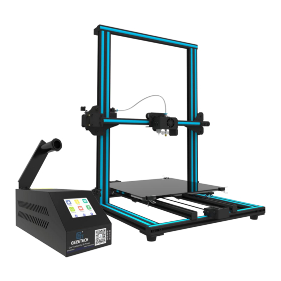
- Page 1 Geeetech A30 3D Printer —Building Instruction—...
-
Page 2: Table Of Contents
Contents Safety Instructions ............................1 Preparation ..............................2 Unfold the Box and Check the Package ....................3 Assembly ..............................4 Wiring ..............................9 Warm Tips .............................16... -
Page 3: Safety Instructions
Safety Instructions Building the printer will require a certain amount of physical dexterity, common sense and a thorough understanding of what you are doing. We have provided this detailed instruction to help you assemble it easily. However, ultimately we cannot be responsible for your health and safety while you are building or operating the printer. -
Page 4: Preparation
Preparation 1. Unpack the kit and check if all parts are in the box. Please check the condition of each part since there might be some damage during shipping. To help you with this, there is BOM in the box and each bag is labeled with its part number. 2. -
Page 5: Unfold The Box And Check The Package
1. Unfold the Box and Check the Package Step1. Unfold the package and take all the parts out to check the condition of the items. As you can see, all the parts are packed very carefully. Step 2. Check the materials. Materials in the Foam box... -
Page 6: Assembly
Bottom frame parts, Vertical frame parts, Control box Materials in the Tool Box 4* M5x20mm hex screws, 4 spring washers, Filament spool, 2* M3x6mm screws, Power cable, Blue A-B USB cord, 2* Z axis stator kits, 3D touch stator, Filament detector kit, Ties, Allen key, Pin, Starter filament, Spare screw package, TF card Tips: 1. - Page 7 Step 3. Use 4* M5x20mm hex screws and 4 spring washers to put the bottom frame parts and the vertical frame parts together.
- Page 8 Step 4. Fix the two Z axis stators on two sides of the vertical frame respectively. Fasten the screws on the stators in a relatively loose way. Note: Pay attention to the direction of the nuts on the Z axis stator.
- Page 9 Right...
- Page 10 Left...
-
Page 11: Wiring
Step 5. Tighten the screws on the Z axis stators. 3. Wiring Step1. Connect the two wires for X axis stepper motor and endstop. - Page 12 Step 2. Connect the two wires for the extruder and filament detector. Step 3. Connect the two wires for Z axis stepper motors and the endstop wire (the left port).
- Page 13 Step 4. Connect the two wires for Y axis stepper motor and endstop.
- Page 14 Step 5. Connect the two wires for the printing head and heatbed to the control box.
- Page 15 Step 6. Fasten the PTFE pipe (for loading filament). Though the other end of the PTFE pipe is pre-assembled, please make sure that it reaches the bottom of the printing head.
- Page 16 Step 7. Attach the filament holder kit to the control box with 2 * M3*6mm. Step 8. Choose the proper voltage (220V / 110V) for A30 by adjusting the switch, according to the power supply standard in your own country.
-
Page 18: Warm Tips
Every machine may have its own calibration procedures and please make reference to the user manual for auto-leveling A30 hotbed. Instead here is a list of key points that should be kept in mind. Frame is stable and correctly aligned. - Page 19 Firmware settings are correct, including: axis movement speeds and acceleration; temperature control; end-stops; motor directions. The point regarding the extruder step rate is vital. Too much extrusion will result in blobs and other imperfections in the print, while too little extrusion will result in gaps and poor inter-layer adhesion.
Need help?
Do you have a question about the A30 and is the answer not in the manual?
Questions and answers