Do you have a question about the MP-24 and is the answer not in the manual?
Questions and answers
Robert Hayes
January 22, 2025
Hello,
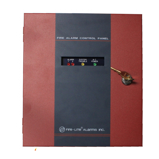
Is the yellow light suppose to be blinking?
1 comments:
Mr. Anderson
May 14, 2025
The yellow TROUBLE LED on the Fire-Lite MP-24 is illuminated during a fault or abnormal condition. It does not normally blink, but the yellow and green LEDs both flash to indicate below normal line voltage (brown-out). So, the yellow light may blink during a brown-out condition.


Need help?
Do you have a question about the MP-24 and is the answer not in the manual?
Questions and answers
Hello, Is the yellow light suppose to be blinking?
The yellow TROUBLE LED on the Fire-Lite MP-24 is illuminated during a fault or abnormal condition. It does not normally blink, but the yellow and green LEDs both flash to indicate below normal line voltage (brown-out). So, the yellow light may blink during a brown-out condition.
This answer is automatically generated