Advertisement
Quick Links
Download this manual
See also:
User Manual
Quick Installation Guide
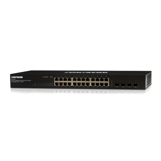
GS-7424 | 24-Port Gigabit Ethernet Smart-Lite Switch
I
I.
Product Information
I-1. Package Contents
1
4
1.
GS-7424 Switch
2.
QIG
3.
Manual CD
2
5
4.
Power Cable
5.
4 x Foot Pads
6.
Rack-Mount Kit
3
6
Advertisement

Subscribe to Our Youtube Channel
Related Manuals for Comtrend Corporation GS-7424


Summary of Contents for Comtrend Corporation GS-7424
- Page 1 Quick Installation Guide GS-7424 | 24-Port Gigabit Ethernet Smart-Lite Switch Product Information I-1. Package Contents GS-7424 Switch Power Cable 4 x Foot Pads Manual CD Rack-Mount Kit...
- Page 2 I-2. Hardware Overview Front Panel The front panel of the switch consists of: • 24 x 10/100/1000Mbps RJ-45 Ports • 4 x SFP Ports • Reset Button • A Series of LED Indicators Rear Panel The rear panel of the switch consists of: •...
- Page 3 I-3. LED Indicator POWER: LED Status Mode Description Green Power on Power off or fail SYS: LED Status Mode Description Green Blinking System ready System not ready Link/ACT: Mode LED Status Description 1000Mbps Green On/Blinking connected/data transmitting 10/100Mbps Amber On/Blinking connected/data transmitting Disconnected or fail...
- Page 4 I-4. Desktop Installation Install the switch on a desktop by attaching the cushioning rubber feet to the bottom corners of the switch to protect against external vibration. Allow adequate space for ventilation between the device and any objects around. I-5. Rack-mounting Installation The switch can be mounted in an EIA standard-sized 19-inch rack that can be placed in a wiring closet with other equipment.
-
Page 5: Quick Setup
Rack Installation Quick Setup II-1. Switch to End Device 1. Connect the switch to local power with the included power cable. 2. Use a standard Cat 5/5e Ethernet cable to connect the switch to end devices as shown below. Switch ports will automatically adjust to the link rate of the device to which it’s connected. -
Page 6: Application Diagram
Application Diagram Switch Gateway VoIP Access Phone Camera Point II-2. Login 1. Open a web browser and go to the switch’s IP address. 2. Enter the access point’s default IP address 192.168.169.1 into the URL bar of a web browser. - Page 7 You will be prompted for a username and password. Enter the default username “admin” and the default password “admin”. 3. You will arrive at the switch configuration window as shown below:...
- Page 8 Your Device is Now Connected! FOR MORE HELP: For instructions on advanced features, FAQ, etc., please visit our online Product Webpage. For more information: YouTube: https://www.youtube.com/user/ComtrendConnection Facebook: https://facebook.com/Comtrend Website: http://us.comtrend.com/ Support: Visit our website or call 1-877-COMTREND (1-877-266-8736)
Need help?
Do you have a question about the GS-7424 and is the answer not in the manual?
Questions and answers