Table of Contents
Advertisement
Available languages
Available languages
INSTRUCTION MANUAL
AutoLaser 3100 Series
Automatic Electronic Self-Leveling
Rotary Lasers
Models
47-3110-GR
47-3150
I I n n s s t t r r u u c c t t i i o o n n M M a a n n u u a a l l
47-3175
M M a a n n u u a a l l d d e e I I n n s s t t r r u u c c c c i i o o n n e e s s
M M a a n n u u e e l l d d ' ' I I n n s s t t r r u u c c t t i i o o n n s s
M M a a n n u u a a l l e e d d i i I I s s t t r r u u z z i i o o n n i i
B B e e d d i i e e n n u u n n g g s s a a n n l l e e i i t t u u n n g g
®
I I n n s s t t r r u u ç ç õ õ e e s s d d e e U U t t i i l l i i z z a a ç ç ã ã o o
Advertisement
Table of Contents

Subscribe to Our Youtube Channel
Related Manuals for David White AutoLaser 3110-GR


Summary of Contents for David White AutoLaser 3110-GR
- Page 1 INSTRUCTION MANUAL AutoLaser 3100 Series Automatic Electronic Self-Leveling Rotary Lasers Models 47-3110-GR 47-3150 I I n n s s t t r r u u c c t t i i o o n n M M a a n n u u a a l l 47-3175 M M a a n n u u a a l l d d e e I I n n s s t t r r u u c c c c i i o o n n e e s s M M a a n n u u e e l l d d ’...
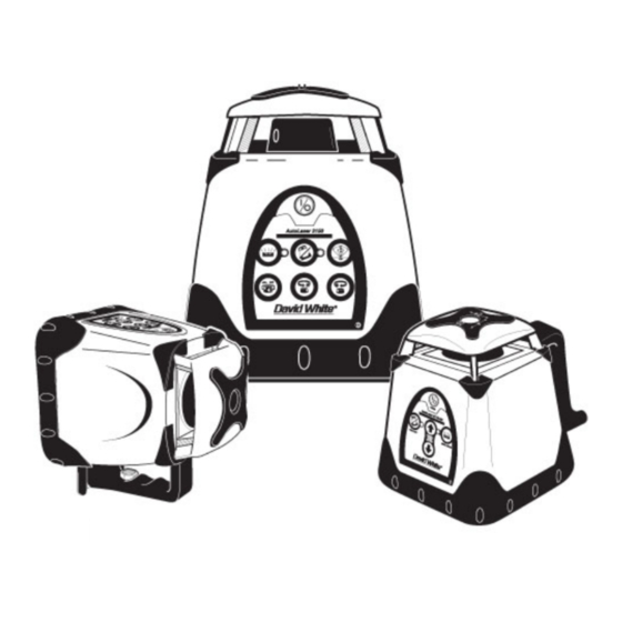
- Page 2 3110-GR- Fig. 1 2 • 3100 SERIES...
- Page 3 3150- Fig. 2 3100 SERIES • 3...
- Page 4 3175- Fig. 3 4 • 3100 SERIES...
- Page 5 Fig. 4 Fig. 5 Fig. 6 Fig. 7 Fig. 8 Fig. 9 3150 / 3110-GR Errors X—AXIS ERROR Y—AXIS ERROR SPINDLE ERROR Fig. 10 “MORE” “MORE” “LESS” “LESS” 3100 SERIES • 5...
-
Page 6: Safety And Certifications
Laser class is indicated on the instrument. Repair and servicing of this laser are to be performed only by David White or authorized service centers. This laser complies with all applicable portions of title 21 of the Code of Federal Regulations set by: the Dept. - Page 7 FEATURES - Fig. 1 , 2 & 3 Reference in ICONS the text Self-Leveling (+/-5º) Rotating Power Button (Allow 60 Laser Head. ( With vertical visible seconds for unit to self-level) split-beam 3150, 3175 only) Battery Level LED Indicator Lights ADS Button–...
- Page 8 NOTE: Setup a Benchmark During the work day, periodically check your initial set-up to ensure that the laser reference has not moved. Establish, at a suitable distance (furthest possible), a benchmark (reference) on a stable surface (ie. tree, building). Periodically during the work day, check the benchmark to ensure that your setup has not moved.
-
Page 9: Operation
Setup a "Benchmark" (page 8). Install the ceiling grid. Attach the magnetic laser target to the ceiling trim being installed. Adjust the height of the trim until the laser beam strikes the target.(Fig. 5) Laydown Applications (3150, 3175) Place the instrument in the laydown position on a flat, level surface. Press the (A) button. - Page 10 Note: For fine adjustment of the vertical laser plane or of the 90° beam, please refer to “Line Position” Variable Rotation Mode (Models 3150 and 3175) The rotation mode will give you the option of increasing or decreasing the speed of the rotating laser.
- Page 11 The display shows “X TOO STEEP or Y TOO STEEP” Turn the instrument OFF, move the instrument to a more level position, then turn the instrument on again. If the instrument continues to poduce errors, contact David White®-Customer Service. 3100 SERIES • 11...
- Page 12 (Fig. 8). If this occurs, see “Troubleshooting”. Model 3175 The display shows “Spindle Motor Error”. If the instrument continues to produce errors, contact David White®-Customer Service. Auto Level Mode (Model 3175) The Auto Level Mode allows you to control how the instrument reacts when moved out of level.
- Page 13 Model 3175 CONT This function is prompted through the Auto Level Mode; it clearly UNIT UNLEVEL signals the user when the instrument is moved out of level. Turn ADS on by selecting it in Auto Level Mode and using the MODE button to return to your desired mode.
- Page 14 Grade Mode – Dual or Single Axis Grade (Model 3175) The dual grade function allows more specialized site preparations such as road grading, airport jobs (grading & paving), irrigation, trenching, landfills, slopes and embankments, and pipelaying. (Fig.11) + >X 0.00% – The Dual Grade Mode screen is the default screen when the instrument >Y 0.00%...
-
Page 15: Replacing Battery
NOTE: If movement occurs in only the grade axis, ADS may not indicate movement since the movement is being detected by the non-grade (level) axis. However, in a real world application, both the grade and level axis will likely move. Line Position Mode (Model 3150 and 3175) In this mode, the instrument allows you to fine-tune the location of your vertical (plumb) laser line. - Page 16 3. Replace the battery tray. Make sure the battery contacts between the battery pack and the instrument compartment are aligned. NOTE: Do not mix old and new batteries. Replace all batteries at the same time with new batteries. Remove batteries before storage of the instrument. Rechargeable Battery Pack If you are using a rechargeable battery pack (Cat #57-NB700), your instrument will provide approximately 14 hours of intermittent use with each full charge.
- Page 17 Upright Position Calibration– X axis model 3110-GR (Fig.16) Power On the instrument with the “A” button while holding the “C” button down, then release the “A” button. You will know if Calibration Mode is activated when the Manual Mode and Anti-Drift LEDs flash alternately. Then, the Manual Mode LED will remain lit; this indicates that the instrument is calibrating within the X axis.(Fig.
- Page 18 If you are unable to calibrate the instrument, or if the difference between positions A and B is too great to calibrate within the numerical range of 430 to 590, please contact David White or an authorized service center for assistance.
-
Page 19: Maintenance And Care
Press the “A” button (“POWER” in the 3175) and allow the instrument to self-level. If necessary, adjust the rotation speed to easily view the laser beam on the wall. Orient the instrument parallel to the wall and attempt to align with your plumb line. (Fig.19) If the laser line does not align with the plumb line, then calibration is necessary. -
Page 20: Specifications
SPECIFICATIONS 3110-GR 3150 3175 650 nm 635 nm 635 nm Beam Type class II/IIIa "hi-powered" "hi-powered" Operating Range Up to 2000-feet (610m) Diameter with Laser Detector with Laser Detector ±1/16-inch@100’ ±1/8-inch@100’ ±1/16-inch@100’ Leveling Accuracy (±1.5mm at 30m) (±3mm at 30m) (±1.5mm at 30m) Electronic Self-Leveling Leveling Type... -
Page 21: Warranty
For warranty and repair information, contact: Your Local Distributor, or David White. For U.S., before returning the instrument to David White, please call (815) 432-9200 for a Return Authorization Number from our Customer Service Department. This Warranty does not cover deficiencies caused by accidental damage, wear and tear, use other than in accordance with the manufacturer's instructions or repair or alteration of this product not authorized by David White. -
Page 22: Universal Laser Detector
UNIVERSAL LASER DETECTOR Introduction The David White® Universal Laser Detector aids in locating and targeting a visible or invisible beam emitted by a rotary laser; perfect for use in outdoor conditions, where sunlight and distance may make locating the beam more difficult. -
Page 23: Remote Control
Special Features– Laser Detector The laser detectors have a unique memory feature, which preserves the last position of the laser beam if the detector is moved out of the plane of laser light, as well as built in electronic filtering for bright sunlight and electromagnetic interference. - Page 24 (1) Variable Rotation – places instrument in Rotation Mode and adjusts to preset rotational speeds. (2) Left Arrow and (3) Right Arrow– Line positioning in laydown position and Grade Adjustment X-Axis – Only in manual mode. (4) Up Arrow and (5) Down Arrow- Grade Adjustment Y-Axis- Only in manual mode / When in laydown position, grade adjustment of the leveling axis (Only in Manual Mode).
- Page 25 Láser autonivelante electrónico Horizontal / Vertical, Plomada, Doble Inclinación manual a través de la pantalla Copyright© 2005 David White. Derechos reservados. Toda esta información es propiedad de David White. Este documento no debe ser copiado o reproducido sin el consentimiento escrito de David White.
- Page 26 CARACTERISTICAS – Fig. 1, 2 y 3 S S Í Í M M B B O O L L O O S S Referencia en el texto Láser rotatorio, campo de autonivelación” de +/- 5° (Cabeza con plomada sólo en los I I n n t t e e r r r r u u p p t t o o r r O O N N / / O O F F F F (conexión / modelos 3150 y 3175) desconexión) –...
- Page 27 E E S S T T A A B B L L E E C C E E R R U U N N A A R R E E F F E E R R E E N N C C I I A A Durante el día de trabajo, compruebe periódicamente la configuración inicial para asegurarse de que la referencia del láser no se ha movido.
- Page 28 Ajuste la distancia del aparato a la rejilla, normalmente unos 1.5” (38 mm) por debajo de ésta). Afloje el tornillo de ajuste y deslice la unidad hacia arriba o abajo a lo largo del soporte de pared. Cuando logre la altura deseada, apriete el tornillo de ajuste para afianzar la unidad.
- Page 29 Rotación vertical (Modelos 3150, 3175) Coloque la unidad en posición “tumbada” sobre una superficie nivelada lisa utilizando la asa, con el panel de control hacia arriba (Fig. 7). Presionar el interruptor “A” una vez (el botón “POWER” en el 3175), y dejar aprox. 60 segundos al láser para que se ponga a nivel.
- Page 30 Modo punto-a-punto. (Modelo 3175) Similar al modo barrido, el modo punto-a-punto permite crear una SELECCIONAR “línea de tiza” laser, barriendo entre dos puntos predeterminados. PTO A PTO Usar el botón SELECT izquierdo para introducir la opción “PTP: IZQU DERECHA SET PT A”, y usar los botones SELECT para rotar la posición del MARCAR PTO A punto de partida hacia la derecha o izquierda.
- Page 31 Si la unidad continua produciendo errores, contactar con el departamento de atención al cliente de David White®. Error “Spindle Motor” – Modelos 3110GR y 3150 Si con el motor en funcionamiento la cabeza no gira, se produce un error de Spindle indicado mediante el encendido intermitiente de los dos LED rojos (Fig.
- Page 32 M M o o d d e e l l o o s s 3 3 1 1 5 5 0 0 , , 3 3 1 1 1 1 0 0 - - G G R R El usuario puede ajustar por defecto en ON o OFF. Con la unidad apagada, mantener pulsado el botón “I”...
- Page 33 (más) y “I” (menos). La cabeza rotatoria se inclina sobre el eje Y. N N o o t t a a : En caso que el láser sea golpeado o desnivelado cuando esté en “modo manual”, la unidad no se autonivela. Como el modelo 3110-GR no tiene pantalla, para programar la inclinación deseada hay que utilizar el receptor láser.
- Page 34 Para salir del Modo Ajuste de las Inclinaciones, mantener presionado el interruptor Mode durante unos 4-5 segundos. Cuando suelte el interruptor, en la pantalla aparecerá el Menú de Selección (no es necesario mantener presionado el interruptor Mode para salir de otras pantallas). N N o o t t a a : Se puede obtener el 10% sólo cuando el láser está...
-
Page 35: Sustitución De Las Pilas
M M o o d d e e l l o o 3 3 1 1 5 5 0 0 Posición de línea será activado únicamente si la unidad es situada en posición de nivelación vertical (panel de control hacia arriba). En esta posición el láser puede trabajar en modo Rotación, Barrido, o Punto. - Page 36 P P i i l l a a s s r r e e c c a a r r g g a a b b l l e e s s En caso que se quiera utilizar un pack de pilas recargables (NB-700), la unidad proporciona aprox. 14 horas de uso intermitente con cada carga completa.
- Page 37 M M o o d d e e l l o o 3 3 1 1 1 1 0 0 - - G G R R ( ( F F i i g g . . 1 1 6 6 ) ) Encienda el láser mientras tiene presionado el interruptor “C”.
- Page 38 Si la calibración no sale bien, o si la diferencia entre los puntos A y B es demasiado grande para corregirla electrónicamente, póngase por favor en contacto con su proveedor o con un centro de Servicio Autorizado David White. Comprobación en la rotación vertical - Eje “Z” (sólo 3150, 3175) Coloque la unidad en posición “tumbada”...
-
Page 39: Mantenimiento Y Conservación
Si esto no es posible, el eje Z debe ser calibrado. Calibración de posición tumbaba – eje Z (sólo 3150, 3175) Apague la unidad presionando el interruptor”A”. M M o o d d e e l l o o 3 3 1 1 5 5 0 0 Encienda la unidad mientras mantiene presionado el interruptor “C”. -
Page 40: Medidas Ecológicas
MEDIDAS ECOLÓGICAS Recuperación de materias primas en lugar de producir desperdicios. Aparato, accesorios y embalaje deberían someterse a un proceso de reciclaje. No tirar las pilas gastadas entre los desperdicios domésticos o al fuego o al agua; eliminarlas de manera ecológica de acuerdo a las directrices legales. DATOS TÉCNICOS 3110-GR 3150... -
Page 41: Solución De Problemas
, , o o D D A A V V I I D D W W H H I I T T E E . Para E.E.U.U., antes de devolver el instrumento a David White, por favor llamar al (815)432-9200 para un Número de Autorización de Devolución del Departamento de Atención al Cliente. - Page 42 Cualquier reparación o reemplazo durante la vigencia de esta Garantía no afecta a su fecha de vencimiento. Dentro de lo autorizado por la legislación vigente, David White no se obliga por esta Garantía a compensar pérdidas como resultado de deficiencias en el producto.
- Page 43 Alimentación Una pila de 9 voltios proporcionará más de tres meses de uso normal. Cuando la unidad esté encendida y el piloto de batería baja permanezca encendido, la pila debe ser sustituida. Quitando la cubierta se permite el acceso a la pila para su sustitución. Funcionamiento En caso de utilización de una mira o regla, montar el receptor mediante su soporte.
- Page 44 DATOS TÉCNICOS D D e e s s c c r r i i p p c c i i ó ó n n L L D D - - 1 1 8 8 N N L L D D - - 1 1 2 2 N N Dimensiones 169 x 76 x 25 mm Peso...
- Page 45 (10)Sleep- posiciona el instrumento en modo “dormir” al apagar todas las funciones excepto los LEDS del panel frontal. Al pulsar cualquier botón del mando, pondrá el instrumento en su ultimo modo de operación. El instrumento se apagará después de 2 horas si ningún otro botón del mando es presionado.
- Page 46 Équerrage, Double Pente Manuelle Copyright© 2005 David White. Tous droits réservés. Les informations contenues dans le présent manuel appartiennent à David White qui se réserve le droit d’apporter toute modification technique sans préavis. Interdiction de copier ou de reproduire le présent manuel sans avoir obtenu auparavant l’autorisation écrite de David White.
- Page 47 FONCTIONNALITÉS - Fig. 1 , 2 & 3 I I C C O O N N E E S S Référence B B o o u u t t o o n n O O N N / / O O F F F F Tête rotative double rayon à...
- Page 48 Remarque : Définition d’un « point de référence » Lors d’une journée de travail, vérifiez à intervalles réguliers votre configuration initiale afin de vous assurer que votre point de référence n’a pas été déplacé. Définissez un point de référence sur une surface stable (un arbre, un bâtiment, etc.), celle-ci devant être aussi éloignée que possible de l’instrument.
-
Page 49: Mode Opératoire
mural est correctement fixé à la cornière. Appuyez sur le bouton “A”. Laissez l’instrument s’autoniveler. Réglez hauteur entre l’instrument et l’ossature, en principe 38 mm (1.5 po) en dessous de celle-ci, à l’aide de la cible magnétique. Desserrez la vis de réglage et faites glisser l’instrument verticalement sur le support de fixation. - Page 50 Une fois le calage terminé, l’instrument repasse en Mode Rotation, sur le modèle 3110-GR, dans le dernier Mode sélectionné avant de l’éteindre, sur le modèle 3150 (par ex., Balayage, Point Fixe ou Mode Rotation; toutefois il ne sauvegarde pas la pente d’information), et dans le Mode Pente, sur les modèle 3175.
- Page 51 touche CHOISIR : la tête oscille entre deux points. CHOISIR Vous pouvez modifier la longueur et la position de la MODELIGNE ligne de balayage. Pour modifier la position, appuyez sur la touche SELECT au-dessus de POS LONG l’indication POS. MODELIGNE Pour la longueur, appuyez sur la touche SELECT au- dessus de l’indication LONG.
- Page 52 L’afficheur montre «X o Y TROP RAIDE». Mettez l’instrument hors tension, repositionnez-le pour le mettre à niveau, puis mettez-le à nouveau sous tension. Si l’appareil continue de faire des erreurs, contactez le service client David White. Erreur fuseau – Disfoncionnement de l’axe rotatif (Spindle Motor Error) M M o o d d è...
- Page 53 niveau automatiquement chaque fois qu’il est heurté ou qu’il se CHOISIR trouve hors niveau. NIVEAU AUTO Si la fonction automatique est désactivée, le laser ne s’arrête pas s’il n’est pas de niveau. Cela peut-être intéressant si vous voulez NIVEAU AUTO utiliser votre laser pour faire des rampants.
- Page 54 L’ADS est sélectionné et entre en fonction une minute après environ pour laisser le temps à l’instrument de se mettre à niveau. Si vous appuyez sur une touche alors que l’ADS est activé, celui-ci attendra une minute supplémentaire avant d’entrer en fonction. En cas de déplacements ou de chocs accidentels, l’ADS bloque la rotation de la tête (le rayon clignote) et empêche que l’instrument de se mette de nouveau à...
- Page 55 M M o o d d è è l l e e s s 3 3 1 1 5 5 0 0 , , 3 3 1 1 1 1 0 0 - - G G R R Pour activer cette fonction, désactivez l’ADS (s’il est activé) puis appuyez sur le bouton « C»; le témoin Manuel clignote.
- Page 56 POUR LES LASERS A PENTE: Pour une meilleur precision en mode pente, positionner avec precision l’instrument avant d’activer le MODE PENTE. POUR LE 3175: Si l’instrument ne peut obtenir la pente désirée, un message d’erreur s’affichera “ERREUR TROP ESCARPE ». Fonction de sécurité...
-
Page 57: Remplacement Des Piles
Balayage et Point fixe. Pour passer au mode Alignement et aligner le rayon laser avec votre point de référence, le laser doit se trouver en mode Rotation. Utilisez les touches «F» ou «G» pour déplacer le rayon vers votre point de référence pendant que la tête tourne (Fig. 13). Si votre instrument se trouve en mode Point fixe ou Balayage, les touches «F»... - Page 58 P P a a c c k k s s A A c c c c u u s s Si vous utilisez un pack accus rechargeable(57-NB700), Votre appareil fontionnera en mode alterenatif, environ 14 heures si les accus sont correctement charges. Les piles n’atteignent leur charge complète qu’après cinq cycles de recharge et décharge.
- Page 59 Étalonnage du positionnement vertical – axe X Laissez l’instrument dans son positionnement actuel. Mettez-le hors tension. M M o o d d è è l l e e 3 3 1 1 1 1 0 0 - - G G R R ( ( F F i i g g . . 1 1 6 6 ) ) Allumez le laser en appuyant simultanément sur le bouton «C».
- Page 60 Si le point “B” se trouve en dessous du point “A”, incrémentez positivement la position du laser par rapport à l’axe X. Si le point “B” se trouve au-dessus du point “A”, incrémentez négativement la position du laser par rapport à l’axe X. Les corrections sont sauvegardées automatiquement.
- Page 61 « + » ou « - » sur le quadrant Y+. Si vous ne parvenez pas à étalonner l’instrument ou si la distance entre les points A et B est trop importante pour pouvoir être étalonnée, veuillez contacter David White ou un centre de service homologué pour obtenir de l’aide.
-
Page 62: Entretien
Les boutons “D” et “F” permettent de modifier la position du laser par rapport à l’axe Z. Le bouton “D” permet d’incrémenter positivement la position du laser par rapport à l’axe Z et le bouton “F” de l’incrémenter négativement par rapport à celui-ci. Sélectionnez le bouton “D”... -
Page 63: Données Techniques
DONNÉES TECHNIQUES 3110-GR 3150 3175 650 nm 635 nm 635 nm Diode laser Classe II/IIIA "high-powered" "high-powered" Portée jusqu’à 600 m (2000 pi) de diamètre avec le détecteur ± 3 mm à 30 m ± 1,5 mm à 30 m ±... -
Page 64: Garantie
1641 et suivants du Code Civil relatifs à la garantie légale des vices cachés. Les produits de mesure et niveaux électroniques David White sont garantis d d e e u u x x a a n n s s contre tout vice de fabrication à... - Page 65 Après diagnostique du Service Après Vente David White , seul compétent à intervenir sur le produit défectueux, celui-ci sera réparé ou remplacé par un modèle identique ou par un modèle équivalent correspondant à l’état actuel de la technique, selon la décision de David White qui en informera le distributeur.
- Page 66 DÉTECTEUR LASER UNIVERSEL Introduction Le détecteur laser universel de David White® sert à localiser un rayon visible ou invisible émis par un laser rotatif. Il est particulièrement indiqué pour l’extérieur, lorsque le soleil et la distance de travail rendent assez complexe ce genre d’opération.
- Page 67 du point de nivellement plus précis, la position médium (utilisée pour une précision supérieure) et le paramètre élevé (utilisé pour un nivellement très précis). Déplacez le détecteur vers le haut lorsque la flèche du bas est allumée (si le bouton du volume est sur marche, vous pouvez entendre une succession de longs signaux sonores).
- Page 68 DONNÉES TECHNIQUES D D e e s s c c r r i i p p t t i i o o n n L L D D - - 1 1 8 8 N N L L D D - - 1 1 2 2 N N Dimensions 169 x 76 x 25 mm Poids...
- Page 69 ( ( 1 1 0 0 ) ) V V e e i i l l l l e e – Place l’instrument en mode « Veille » en coupant toutes les fonctions sauf l’écran face LED. Presser n’importe quel bouton de la télécommande remettra l’instrument dans les derniers modes opératoires utilisés.
- Page 70 Raggio a Squadro, Doppia pendenza manuale con display. Copyright© 2005 David White. Diritti riservati. Le informazioni contenute in questo manuale sono di proprietà della David White , che si riserva di apportare modifiche tecniche senza preavviso. E’ vietato copiare o riprodurre questo manuale senza previo consenso scritto della David White.
- Page 71 CARATTERISTICHE - Fig. 1, 2 & 3 S S I I M M B B O O L L I I Riferimento nel testo Testa laser, autolivellante entro +/-5° (Raggio a squadro solo 3150 e 3175) P P u u l l s s a a n n t t e e O O N N / / O O F F F F (tempo LED livello batterie (solo 3110-GR e 3150) massimo di autolivellamento 60 sec)
- Page 72 R R i i f f e e r r i i m m e e n n t t i i . . Durante il vostro lavoro, verificate regolarmente il posizionamento del laser, in modo da assicurarvi che la quota di lavoro non sia variata. Fissate ad una distanza appropriata (il più...
-
Page 73: Funzionamento
montaggio del perimetrale. Abbassate ora il laser facendolo scorrere sulla staffa, in modo che l’uscita del raggio si trovi a 38 mm dalla base inferiore del perimetrale. Una volta raggiunta l’altezza desiderata, bloccate la vite di regolazione posta sul lato della staffa. Utilizzando il piano di luce laser e la mira magnetica, livellate la griglia del controsoffitto regolando l’altezza dei pendini di fissaggio.(Fig. - Page 74 modello 3110-GR, nell’ultimo Modo selezionato prima dello spegnimento nel modello 3150 (per es. Scansione, Punto Fisso, o Modo Rotazione; NON memorizza tuttavia l’impostazione della pendenza manuale), e nel Modo Pendenza nel modello 3175. Piombi / Piani verticali (Modelli 3150, 3175) Appoggiate il livello su una su una superficie piana e livellata utilizzando la maniglia di appoggio, in modo che la tastiera sia rivolta verso l’alto.(Fig.
- Page 75 Per la lunghezza premete il tasto SELECT sopra l’indicazione LUNG. E’ possibile regolare la lunghezza della linea di scansione tra 3° e 359°. Il modo SCANSIONE impostato resta in memoria quando si spegne il laser. Linea tra due punti (Modello 3175) Questa funzione simile al modo SCANSIONE, consente di tracciare una linea laser tra due punti selezionati a piacere.
- Page 76 è +/- 5°. Se lo strumento continua a dare indicazioni di errore, mettetevi in contatto con un Centro Assistenza Autorizzato David White. Errore di rotazione (Spindle Error) M M o o d d e e l l l l i i 3 3 1 1 1 1 0 0 - - G G R R e e 3 3 1 1 5 5 0 0 Se la testa del laser non ruota, oppure ruota ma non alla velocità...
- Page 77 M M o o d d e e l l l l i i 3 3 1 1 5 5 0 0 , , 3 3 1 1 1 1 0 0 G G R R Questa funzione è selezionabile dall’operatore, che può impostarla in modo da averla ON o OFF di default all’accensione del laser.
- Page 78 Premendo il tasto”C” si disattiva il sensore di livello: il LED corrispondente lampeggia per ricordare che lo strumento funziona in modo completamente manuale (tutti i controlli esclusi). Premendo i tasti “H” (PIU’) o “I” (MENO) è possibile impostare la pendenza desiderata. La testa si inclinerà...
- Page 79 raggiungere la pendenza desiderata solo dopo che lo strumento si è livellato. Una volta impostate le percentuali di pendenza, lasciate tempo al laser perché raggiunga le pendenze impostate e aspettate che la testa inizi a girare. Fate riferimento alla Fig. 12 per prevedere il risultato in funzione della inclinazione impostata sui due assi.
-
Page 80: Sostituzione Delle Batterie
Modo Allineamento (Modelli 3150, 3175) Con questa funzione è possibile eseguire allineamenti di elementi verticali, quali pilastri, facciate continue o pareti in cartongesso, o allineamenti e squadri negli interni, in maniera estremamente veloce, senza muovere fisicamente il laser. Una volta allineato il piano di luce verticale con il vostro riferimento, il laser rimane allineato anche quando si impostano i modi Rotazione, Scansione, Punto fisso. - Page 81 3. Riposizionate il piatto porta batterie, allineando i contatti con quelli dello strumento. Avvitate a fondo la rondella di plastica. N N o o t t a a : non mischiate batterie nuove e vecchie. Sostituite TUTTE le batterie allo stesso tempo. Togliete sempre le batterie prima di immagazzinare lo strumento.
- Page 82 Calibrazione dell’asse X M M o o d d e e l l l l o o 3 3 1 1 1 1 0 0 - - G G R R ( ( F F i i g g . . 1 1 6 6 ) ) Non muovete il laser dalla sua posizione attuale e spegnetelo.
- Page 83 Si consiglia di ripetere la procedura di controllo descritta al capitolo precedente (punti 1-4) per verificare l’esattezza delle correzioni date. La verifica della calibrazione può essere eseguita in Modo Calibrazione. M M o o d d e e l l l l o o 3 3 1 1 7 7 5 5 LING ASSE X FINE...
- Page 84 Se non riuscite a calibrare il laser, o se la differenza tra i punti “A” e “B” è troppo grande per essere corretta con una calibrazione elettronica, mettetevi in contatto con il vostro rivenditore o con il ns. centro assistenza David White. Verifica del PianoVerticale – Asse Z (Solo modelli 3150, 3175)
-
Page 85: Cura E Manutenzione
Selezionate “+” per ruotare il punto laser in senso antiorario, oppure “-” per ruotarlo in senso orario in modo da allineare il piano verticale con il vostro riferimento. Premete il pulsante MODE per uscire dal Modo Calibrazione dell’Asse Z, e salvate le variazioni apportate spegnendo il laser (“FINE”). -
Page 86: Dati Tecnici
DATI TECNICI 3110-GR 3150 3175 650 nm 635 nm 635 nm Tipo laser Classe II/IIIA "high-powered" "high-powered" Portata fino a 610 m di diametro con il ricevitore Precisione ± 3 mm a 30 m ± 1,5 mm a 30 m ±... -
Page 87: Garanzia
David White , garantisce questo prodotto riguardo a difetti nei materiali o della manodopera per d d u u e e a a n n n n i i dalla data d’acquisto. I prodotti difettosi saranno riparati o sostituiti, a discrezione di David White, se inviati assieme alla prova d’acquisto. - Page 88 Calibrazione e manutenzione non sono coperti da garanzia. La David White si riserva di apportare modifiche tecniche senza preavviso. RICEVITORE LASER UNIVERSALE...
-
Page 89: Manutenzione
Dirigere la finestra di ricezione del raggio verso il laser rotativo. Muovere lentamente il ricevitore verso l’alto o verso il basso fino a che non compaiono le frecce e/o non si sente un segnale audio. Selezionare la banda di precisione desiderata, a seconda delle condizioni di lavoro e della precisione richiesta. - Page 90 Specifiche Tecniche D D e e s s c c r r i i z z i i o o n n e e L L D D - - 1 1 8 8 N N L L D D - - 1 1 2 2 N N Dimensioni 169 x 76 x 25 mm Peso...
- Page 91 dell’inserimento della funzione “Sleep”. Se invece entro due ore dall’inserimento di questa funzione non viene premuto nessuno degli altri tasti del telecomando, il laser si spegnerà completamente. TELECOMANDO 57-RC400X (Fig.24) - Solo per il modello 3175 Il telecomando opzionale 57-RC400X controlla tutte le funzioni del livello, ad eccezione dell’accensione, dell’ADS e della calibrazione.
- Page 92 Horizontal/Vertikal, Lotstrahl, Zwei Neigungen mit Display Copyright © 2005 David White. Alle Rechte vorbehalten. Die hier enthaltenen Angaben sind geistiges Eigentum von David White und dürfen ohne Zustimmung von David White weder verwendet, noch verändert werden Dieses Dokument darf ohne schriftliche Zustimmung von David White weder kopiert noch anderweitig weiterverarbeitet werden.
- Page 93 G G E E R R Ä Ä T T E E M M E E R R K K M M A A L L E E - - A A b b b b . . 1 1 , , S S C C H H A A L L T T E E R R - - S S Y Y M M B B O O L L E E Referenz 2 2 u u n n d d 3 3...
- Page 94 A A c c h h t t u u n n g g : : E E i i n n r r i i c c h h t t u u n n g g e e i i n n e e r r R R e e f f e e r r e e n n z z h h ö ö h h e e Überprüfen Sie während der Arbeit in regelmäßigen Abständen die ursprüngliche Arbeitshöhe um sicherzustellen, dass Sie sich nicht verändert hat.
-
Page 95: Bedienung
Vertikaleinsatz -Ausrichten von Stützen, Wänden,etc. (nur 3150, 3175) Gerät auf einen flachen, ebenen Untergrund über einen definierten Punkt aufstellen. Gerät einschalten und abwarten bis es sich nivelliert hat (Abb. 6). Zum Feineinstellen der Laserebene auf die vorgegebene Flucht (in der Regel definiert durch 2 Punkte) kann mit Hilfe der links/rechts Tasten auf der Fernbedienung im Vertikalbetrieb die Ebene nach links bzw. - Page 96 Einsatz Vertikal (Modelle 3150, 3175) Stellen Sie den Laser auf seinen Griff auf einen ebenen, festen Untergrund (Tastatur nach oben) – Abb. 7. Drücken Sie die „A“ Taste einmal und geben Sie dem Gerät Zeit (bis zu 60 Sek.) um sich einzunivellieren.
- Page 97 Strich mittig aus, danach kann noch die Strichlänge (von 359º bis 3º) angepasst werden (Winkel). Die zuletzt gewählte Strichlänge wird abgespeichert und bei der nächsten Auswahl des Linienmodus wieder aufgerufen. Punkt zu Punkt Modus (Modell 3175) Diese Funktion erlaubt Ihnen 2 Punkte (A und B) festzulegen, AUSWAHL zwischen denen der Laser scannt.
- Page 98 Störung des Nivelliervorgangs (Axis Drive Error - Modelle 3110-GR und 3150 Wenn der Laser zu schräg aufgestellt oder so angestoßen wurde, das er sich außerhalb seines Selbstnivellierbereichs von +/- 5° befindet, wird er trotzdem versuchen sich einzurichten. Wenn die Grenze des Nivellierbereichs erreicht wird, wird ein Fehler angezeigt (Abb. 8). Schalten Sie in diesem Fall den Laser aus, korrigieren Sie die Aufstellung und schalten Sie den Laser wieder ein.
- Page 99 Wenn AUTOM..NIVELL aktiviert ist, dann nivelliert sich das AUSWAHL Instrument automatisch wenn es verschoben wurde und arbeitet AUTOM. NIVELL im eingestellten Modus weiter. ´ Ist AUTOM..NIVELL ausgeschaltet „AUS“ erscheint im Display, AUTOM. NIVELL dann nivelliert sich das Gerät nicht nach und kann mit Hilfe einer Neigungsplatte auch mehr als 10% geneigt werden.
- Page 100 gleichzeitig einschaltet. Wenn das Gerät dann an ist, nochmals für 15 Sekunden ausschalten damit die Einstellung abgespeichert wird.. Neigungseinstellung – Eine Achse (Modell 3110-GR) Die Neigung in einer Achse eignet sich zur Baggersteuerung, zum Legen von Drainagen und vielen anderen Aufgaben (Abb. 9). Die Neigung kann man von –10% bis zu +10% in Y-Achse einstellen. Die Achsen sind oben am Gehäuse mit X und Y gekennzeichnet.
- Page 101 Beim Einschalten erscheint die Anzeige für die Neigungseingabe (X/Y). Durch einmaliges drücken der Mode-Taste wechseln Sie von der X-Wert Eingabe in die Y-Wert + >X 0.00% – Eingabe. Das Symbol > zeigt die gewählte Achse an. Drücken Sie die linke >Y 0.00% –...
- Page 102 ADS wird nach jeder Änderung des Neigungswertes für 30s deaktiviert. A A c c h h t t u u n n g g : theoretisch ist es möglich, dass eine Positionsänderung vom der ADS Überwachung nicht erkannt wird, wenn sich das Gerät absolut genau in der geneigten Achse neigt. Im praktischen Einsatz ist dies jedoch sehr unwahrscheinlich.
- Page 103 1. Dazu entfernen Sie die Bodenplatte des Geräts, lösen Sie dazu die Befestigungsmutter auf der Unterseite. 2. Entnehmen Sie die 4 Batterien und ersetzen Sie diese durch Neue. 3. Setzen Sie den Batteriehalter wieder ein. Stellen Sie sicher, dass die Kontakte aneinander liegen und auch Kontakt haben.
- Page 104 Wiederholen Sie die Schritte 1-4 um sicher zu stellen, dass diese Ablesungen korrekt sind. Sollte der Abstand zwischen A und B größer sein, dann muß die X Achse kalibriert werden. A A c c h h t t u u n n g g : Bei den Modellen 3150 und 3175 kann man den Punkt Modus ohne Empfänger verwenden.
- Page 105 Y-Kalibrier Modus umgeschaltet. Sollte der Laser so stark dejustiert sein, dass eine Kalibrierung über die Tasten nicht möglich ist, dann wenden Sie sich bitte an Ihren Händler oder an eine von David White autorisierte Fachwerkstatt. 3100 SERIES • 105...
- Page 106 Überprüfung Vertikal – Z Achse (nur 3150, 3175) Gerät auf einen ebenen und flachen Untergrund ca. 30m von einer Wand aufstellen (Tastatur nach oben). Befestigen Sie ein Lot mit einer mindestens 2,5 m langen Schnur an der Wand. Schalten Sie das Gerät ein und lassen Sie ihm Zeit sich selbst zu nivellieren (bis zu 60sec.). Falls nötig, stellen Sie die Rotationsgeschwindigkeit des Kopfes so ein, daß...
-
Page 107: Pflege Und Wartung
PFLEGE UND WARTUNG Das Gerät nach Gebrauch immer reinigen. Mit einem weichen, trockenen Tuch jegliche Feuchtigkeit entfernen. Keine scharfen Reinigungs- oder Lösemittel verwenden. Bewahren Sie den Laser im Koffer auf. Vor einer langen Lagerung Batterien entfernen. UMWELTSCHUTZ Rohstoffrückgewinnung statt Müllentsorgung. Gerät, Zubehör und Verpackung sollten einer umweltgerechten Wiederverwertung zugeführt werden. -
Page 108: Technische Daten
TECHNISCHE DATEN 3110-GR 3150 3175 Lasertyp 650 nm 635 nm 635 nm Klass II/IIIA "high-powered" "high-powered" Arbeitsbereich bis 610 m Durchmesser mit Laserempfänger Nivelliergenauigkeit ± 3 mm auf 30 m ± 1,5 mm auf 30 m ± 1,5 mm auf 30 m elektronisch Selbstnivellierung Horizontal... - Page 109 2 2 J J a a h h r r G G a a r r a a n n t t i i e e Zusätzlich zu jeglichen gesetzlichen oder vertragsgemäßen Garantien, die der Käufer (Verbraucher oder Betrieb) gegenüber seinem Händler haben kann, gewährt David White , – auf Wunsch des Käufers – folgende Garantie, die kein gesetzliches Recht des Käufers dieses Produktes beeinträchtigt:...
- Page 110 David White autorisiert wurde, entstanden sind. Reparatur oder Ersatz durch diese Garantie beeinträchtigen nicht das Ablaufdatum der Garantie. David White haftet nicht durch diese Garantie für indirekten oder Folgeschaden, der aus den Fehlern dieses Produktes entsteht. Diese Garantie darf nicht ohne die Genehmigung von David White verändert werden.
- Page 111 Stromversorgung Mit einer 9-volt Batterie erreicht der Laserempfänger im normalen Arbeitsbetrieb eine Batteriedauer von ca. 3 Monaten. Wenn der Empfänger eingeschaltet ist und die Batterieanzeige leuchtet, muß die Batterie ersetzt werden. Bedienung Befestigen das den Empfänger im Bedarfsfall an eine Lasernivellierlatte (06-TLM).
- Page 112 Wartund und Pflege Die Laserempfänger sind mit O-Ringen versehen und dadurch vor Staub und Wasser geschützt. Mit einem weichen, trockenen Tuch jegliche Feuchtigkeit entfernen. Keine scharfen Reinigungs- oder Lösemittel verwenden. Vor einer langen Lagerung Batterie entfernen. Technische Daten M M o o d d e e l l l l L L D D - - 1 1 8 8 N N L L D D - - 1 1 2 2 N N Maße...
- Page 113 ( ( 8 8 ) ) S S c c a a n n M M o o d d u u s s : : 10, 45, 90, 180º ( ( 9 9 ) ) D D i i e e M M a a n n u u e e l l l l T T a a s s t t e e schaltet das Gerät in den manuellen Modus, wenn ADS nicht aktiv ist. In manuellen Modus kann auch die Vertikale geneigt werden.
- Page 114 A A u u s s r r i i c c h h t t e e n n i i m m V V e e r r t t i i k k a a l l e e i i n n s s a a t t z z - Mit den Tasten “Left” und “Right” kann die Laserebene oder der Lotstrahl im Vertical-Betrieb (Bedienfeld des Lasers zeigt nach oben) ausgerichtet werden.
- Page 115 Rampa Dupla Digitalizada Copyright© 2005 David White. Todos os direitos reservados A informação contida neste manual é informação de propriedade da David White, e está sujeita a alteração sem aviso prévio. Este documento não poderá ser copiado ou em qualquer caso reproduzido sem o consentimento escrito da David White.
- Page 116 CARACTERÍSTICAS - Fig. 1, I I C C O O N N E E S S Referência 2 & 3 no texto Laser Rotativo Auto nivelável (+/-5º) – Tecla I I n n t t e e r r r r u u p p t t o o r r O O N N / / O O F F F F (Duplo Raio só...
- Page 117 Estabelecer uma Cota de Referência Periodicamente durante o dia de trabalho, verifique a sua cota de referência (ex.:cota de soleira) para se assegurar que a altura do plano laser não se alterou. Estabeleça, uma distância razoável (mais distante quanto possível) uma cota de referência numa superfície estável (ex.
- Page 118 Ligue o aparelho. Espere que se auto nivele. Acerte a distância vertical entre a estrutura do tecto falso e o plano de luz laser, tipicamente 38 mm. Afrouxar o parafuso de fixação da corrediça vertical do suporte e parede para acertar a referida distância vertical.
- Page 119 no último modo seleccionado de operação (i.e. Modo de Varrimento, Ponto, e Rotação; contudo, não retém a informação da percentagem de rampa) para 3150, e no Modo de Rampa para o 3175. Prumo / Posição Deitada (Modelo 3150, 3175) Colocar o aparelho deitado sobre a sua asa suporte, numa superfície plana (Com o teclado para cima) (Fig.
- Page 120 varrimento do raio laser. O varrimento pode ser tão largo como 359° ou tão pequeno quanto 3°. A última selecção de varrimento ficará em memória e será activada quando ligado o varrimento. Modo de Ponto-a-Ponto (Modelo 3175) Semelhante ao modo de Varrimento, o Modo de Ponto-a-Ponto pode criar uma linha laser e riscar o espaço entre dois pontos SELEC previamente seleccionados.
- Page 121 medições, pelo operador. O Sistema de Segurança de Altura (Anti Drift System) é usado para este propósito (Ver ADS). O instrumento pode ser colocado no Modo Manual para permitir que continue a trabalhar quando fora de nível. Erro de Auto Nivelamento (Axis Drive Error) - (Modelos 3110-GR e 3150) Se o laser é...
- Page 122 Use a tecla SELECT esquerda para LIGAR ou DESLIGAR a opção de Auto Nivelamento. Você também pode impor o Modo de Segurança de Altura (ADS) no nível. Sistema de Segurança de Altura (Anti Drift System) - ADS - (Todos os Modelos) O Sistema de Segurança de Altura, quando LIGADO, informa o operador quando o aparelho sai de nível.
- Page 123 Modo de Rampa - Rampa Simples (Modelo 3110-GR) A função de rampa simples é a ideal para trabalhos de rampa em geral, escavações, drenagem, saneamentos, etc. (Fig. 9). A rampa seleccionada pode ser tanto positiva como negativa até 10%, e pode impor-se no eixo Y do aparelho, impresso e em relevo na carcassa do instrumento.
- Page 124 Modo de Rampa - Rampa de Dupla Pendente (Modelo 3175) A função de rampa de dupla pendente permite trabalhos mais especializadas como estradas, arruamentos, trabalhos de aeroporto, irrigação, valas, aterros sanitários, rampas e diques etc. (Fig. 11). A mensagem do Modo de Rampa Dupla aparece por defeito quando o aparelho é ligado. Usar a tecla de Modo para escolher o eixo-X ou o eixo-Y.
- Page 125 No Modo de Rampa, quando a unidade sair de nível, a cabeça do SELEC laser pára a rotação e o raio pisca. O operador, usando a tecla AUTO NIVEL SELECT selecciona a opção “ CONTinue”. AUTO NIVEL N N o o t t a a : Se acontece um movimento em rampa simples, teoricamente o ADS pode não indicar esse movimento se o mesmo for detectado pelo eixo que está...
- Page 126 deitado, pode ser usado nos modos de Rotação, ponto ou Ponto-a-Ponto. Para entrar no modo de Posição de Linha, usar a tecla de Modo para ir para a opção de Posição de Linha e pressionar a tecla select. O instrumento rodará à última velocidade de rotação seleccionada. Pressionar as teclas SELECT para mover a posição do ponto para a direita ou para a esquerda para alinhamento perfeito com o alvo (Fig.
- Page 127 Verificação Posição Vertical - eixo de X (Todos os Modelos) Para verificar o eixo X, montar o laser num tripé ou colocá-lo numa superfície lisa e estável a aproximadamente 30m de uma parede. Vire a face “ X+ “ da unidade para a parede (Fig. 16).
- Page 128 Os ajustes são guardados em memória automaticamente. O teste deve ser repetido para se assegurar de que se fez a calibração correta. O teste pode ser feito no Modo de Calibração. M M o o d d e e l l o o 3 3 1 1 5 5 0 0 Ligar o aparelho mantendo a tecla “C”...
- Page 129 Se está impossibilitado de calibrar a unidade, ou se a diferença entre pontos A e B é muito grande para calibrar dentro do alcance numérico de 430 a 590 (recebendo uma mensagem de “Spindle Error”), por favor contacte David White ou um centro de serviço autorizado para ajuda. Verificação Posição Horizontal - eixo Z (Só 3150, 3175) Para verificar o eixo Z, colocar o aparelho deitado sobre a sua pega/suporte (painel das teclas virado para cima), numa superfície plana e estável a 30m de uma parede, em posição...
-
Page 130: Manutenção E Cuidados
M M o o d d e e l l o o 3 3 1 1 5 5 0 0 Ligar o aparelho, mantendo a tecla “C” pressionada. O Modo de Calibração está ativado quando os indicadores do Modo Manual e do ADS piscam alternadamente. As teclas “D”... - Page 131 ESPECIFICAÇÕES 3110-GR 3150 3175 650 nm 635 nm 635 nm Classe do Raio II/IIIA "muito potente " "muito potente" Alcance até 610 m de diâmetro com receptor laser Precisão horizontal ± 3 mm @ 30m ± 1,5 mm @ 30m ±...
- Page 132 Se a unidade gira mas não se auto nivela, verificar se o Modo de Auto Nivelamento não está desligado no modelo 3175, ou que nos modelos 3110-GR e 3150 o Modo Manual esteja activado. Se estas soluções não são efetivas, por favor contacte a David White ou um centro de serviço autorizado, para ajuda.
- Page 133 Nada nesta garantia deve limitar os direitos da David White sobre os compradores no cabo de 1) Morte ou acidentes pessoais causados pela sua negligencia ou 2) mau comportamento intencional ou grave negligencia.
- Page 134 Alimentação Uma bateria de 9 V alimenta até 3 meses, em uso típico. Quando a unidade é ligada eo símbolo de bateria baixa aparece, a bateria deve ser substituída. Funcionamento Monte o receptor num bastão. Ligue-o pressionando o interruptor. Os símbolos do LCD ficarão intermitentes durante algum tempo;...
- Page 135 Especificações D D e e s s c c r r i i ç ç ã ã o o L L D D - - 1 1 8 8 N N L L D D - - 1 1 2 2 N N Dimensões 169 x 76 x 25 mm Peso...
- Page 136 Por favor se consultar a Secção de Operação do manual para completar as instruções de operação. CONTROLO REMOTO RC400X (Fig. 24) – Só para o modelo 3175 Esta secção cobre o uso do controle remoto opcional (57-RC400X). O controlo remoto, controla todas as funções excepto ligar e desligar, ADS, e calibração, tendo um alcance de até...
- Page 137 Fig. 14 Fig. 11 Fig. 13 Alignment Target Alignment Target Fig. 12 Fig. 15 X= –10.00% Y= –10.00% X= +10.00% Y= +10.00% X= –10.00% Y= +10.00% Fig. 16 100' (30m) X+ Facing the Target (i.e. wall, detector) 3100 SERIES • 137...
- Page 138 Fig. 17 Fig. 18 Location of Location of Location of Calibration Buttons Calibration Buttons Calibration Buttons Calibrated Y+ Facing the Target (i.e. wall, detector) Fig. 19 Fig. 21 Rotating Beam (Dashed Line) is shown NOT in-line with plumb line Plumb Beam Fig.
- Page 139 Fig. 22 Fig. 23 Fig. 24 10 10 P TO P ROTATE SWEEP LONG SHORT DOWN Remote Control Remote Control Rotary Laser Levels Rotary Laser Levels Function Buttons Function Buttons Sweep/Scanning– Preset Angles Long Sweep/Scanning– Increase Angle Variable Speed Rotation Short Sweep/Scanning–...
- Page 140 David White 255 W. Fleming Street Watseka IL 60970 USA 767441 Z94-3100-7 (0919)
Need help?
Do you have a question about the AutoLaser 3110-GR and is the answer not in the manual?
Questions and answers