
Related Manuals for David White DWT-10


Summary of Contents for David White DWT-10
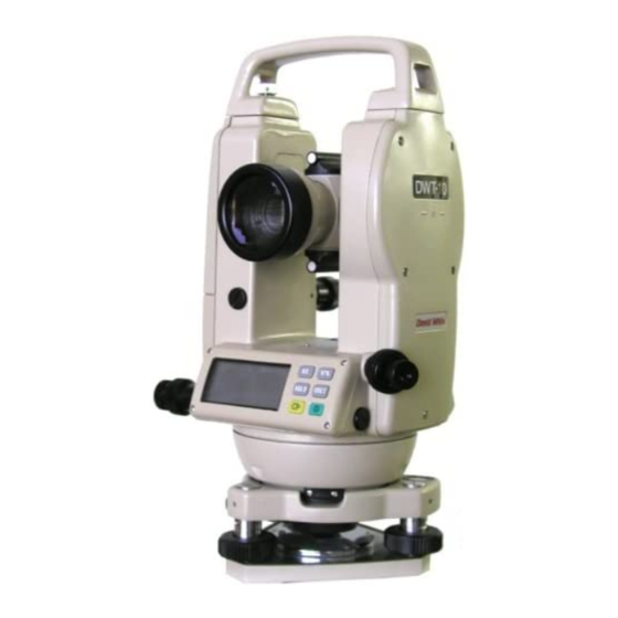
- Page 1 ® DWT-10 Instruction Manual For Customer Service Call (781) 848-7702 or Fax (781) 848-8022...
-
Page 2: Table Of Contents
Congratulations on your choice of this David White® Electronic Digital Transit. We suggest that you read this instruction manual carefully before using the instrument. By thoroughly familiarizing yourself with the instrument and its operation, you will be able to obtain the full benefit of this superior precision instrument. Save this instruction manual for future use. -
Page 3: Before You Use
IMPORTANT! READ THIS BEFORE USING YOUR INSTRUMENT This quality David White ® instrument has been inspected twice for accuracy before leaving the factory. The instrument has also been given the best protection possible against damage during transportation. Even with these precautions, the instrument is subject to rough handling during shipment. -
Page 4: Warranty Information
WARRANTY ® David White (Seller) warrants the equipment of its manufacture to be free of defects in workmanship and material for a period of one year from date of purchase. If within such one year period the original purchaser (Buyer) notifies Seller, in writing, that the... -
Page 5: Nomenclature And Functions
1. NOMENCLATURE AND FUNCTIONS 1.1 Nomenclature... -
Page 6: Part Functions
1.2 Part Functions V -8.8.8.8.8.8.8. HOLD OSET 8.8.8.8.8.8.8. 1.2.1 Display DISPLAY FUNCTION Vertical angle symbol will be shown in place of the vertical reading until the telescope has been turned past the zero point of the horizontal axis. This sets the zero point. HOLD OSET 0.0.0.0.0.0.0. -
Page 7: Operating Keys
1.2.2 Operating Keys KEY SYMBOL FUNCTION OPERATION Used to switch horizontal angle between clockwise rotation (H ) and Setting horizontal counterclockwise rotation (H angle rotational The direction changes each direction time the button is pressed. Used to lock current horizontal angle into display. -
Page 8: Setting Up Your Measuring Preferences
1.2.3 Setting Up Your Measurement Preferences A) Turn the power on. B) Press “R/L” and “V%” at the same time. A tone will be heard and the display should look similar to what’s shown at right. C) To specify your measurement preferences: PRESS DISPLAY Change the readout of the... - Page 9 1.2.3 Preferences continued Once all preferences have been input, press the “H/R” and “V%” at the same time. A long tone will be heard and the display will return to normal.
-
Page 10: Preparations For Measurement
2. PREPARATION FOR MEASUREMENT 2.1 Mounting And Leveling Mount and level the instrument carefully to get the best performance. 1. Place the tripod over the ground datum point and tighten the legs. 2. Attach the instrument to the tripod and tighten snugly 3. -
Page 11: Telescope Eyepiece Focus
5. Centering the instrument using the optical plummet A) Adjust the eyepiece so the bull's-eye reticle comes into sharp focus. B) Adjust focus knob so ground target comes into sharp focus. C) Slightly loosen the tripod fastening screw and move the instrument until the ground target is centered in the optical plummet. -
Page 12: Aiming At The Target
2.3 Aiming At The Target Loosen the clamps and point at the target using the targeting sights located above and below the telescope. Allow some space between your eye and the targeting sight. 3. MEASUREMENT 3.1 Power 1. Turn the power on. All V -8.8.8.8.8.8.8. -
Page 13: Measuring Horizontal Angles
3.2 Measuring Horizontal Angles 1. Aim at target “A” 2. Press “0SET” key to zero out horizontal angle reading, HR 0°00'00". 3. Aim at second target, “B”, and the angle between “A” and “B” will be displayed, HR 30°15’00". “HR” shown on the display means that the horizontal angle reading increases as you turn the instrument clockwise. -
Page 14: Stadia Measurement
3.6 Stadia Measurements 1. Distance measurement can be done using the stadia hairs of the reticle. 2. Read the length " l " of a level rod shown between the stadia hairs. 3. The distance to the target is 100 multiplied by "... -
Page 15: Handling Of Power Supply
4. HANDLING OF POWER SUPPLY 4.1 Removing The Battery Compartment Push down on the battery compartment latch and pull the top of the battery compartment away from the instrument. 4.2 Replacing Batteries 1. Push down on the hook to remove the metal battery door. -
Page 16: Checks And Adjustments
5. CHECKS AND ADJUSTMENTS 5.1 Adjustment Precautions When attempting to check and adjust an instrument, corrections must be done in a certain order or the adjustments will not be correct. Order of adjustment: 1. Check and adjust the plate vial. 2. -
Page 17: The Optical Plummet
3. Optical Plummet This adjustment is required to make the line of sight of the optical plummet coincide with the vertical axis. A) Point the optical plummet at a ground target. This can be done by adjusting the level screws or by loosening the instrument fastening screw and moving the instru- ment over the target. -
Page 18: Tribrach
6. TRIBRACH Removal: Turn the locking lever 180° counterclockwise. The instrument can now be removed from the tribrach. Attachment: Line up the tongue on the instrument with the notch in the tribrach. Turn the locking lever 180° clockwise. 7. ACCESSORIES Standard Equipment: Carrying case, Sunshade, Tool kit, Rain cover, Drying cloth, Plumb bob Optional equipment: Rechargeable battery, Charger, Tripod, Diagonal eyepiece, Level... -
Page 19: Specifications
9. SPECIFICATIONS Overall Length 155mm (6.1") 45mm (1.77") Objective aperture Magnification Erect Image Field of view 1° 30' TELESCOPE 2.5" Resolving power Minimum focus 1.3M (53") 100 to 1 Stadia Ratio Stadia constant Incremental Method ELECTRONIC 5"/10" (3/5 mog) Minimum reading ANGLE 10"... - Page 20 ® P.O Box 359, Watseka, IL 60970 USA (800) 435-1859 • (815) 432-5237 FAX (815) 432-5390 www.davidwhite.com P/N DWT10MANL 08/02...
Need help?
Do you have a question about the DWT-10 and is the answer not in the manual?
Questions and answers