Table of Contents
Advertisement
Advertisement
Table of Contents

Subscribe to Our Youtube Channel
Related Manuals for Michell Instruments Easidew PRO XP


Summary of Contents for Michell Instruments Easidew PRO XP
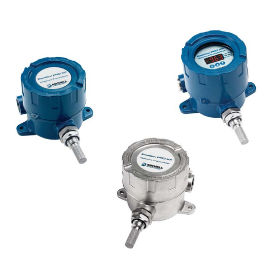
- Page 1 Easidew PRO XP Moisture Transmitter User’s Manual 97442 Issue 5 May 2018...
- Page 2 Please fi ll out the form(s) below for each instrument that has been purchased. Use this information when contacting Michell Instruments for service purposes. Instrument Code Serial Number Invoice Date Location of Instrument Tag No Instrument Code Serial Number Invoice Date...
- Page 3 © 2018 Michell Instruments This document is the property of Michell Instruments Ltd. and may not be copied or otherwise reproduced, communicated in any way to third parties, nor stored in any Data Processing System without the express written authorization of Michell Instruments Ltd.
-
Page 4: Table Of Contents
2.7.3 Electrical Boundaries ................... 15 Preparation of the Sensor Cable ................ 16 2.8.1 Terminal Block Connection - Easidew PRO XP EX1 (Non-Display) ....16 2.8.2 Terminal Block Connection - Easidew PRO XP EX2 (Display) ......17 OPERATION ....................19 Measurement and Confi guration ................ 19 Sampling Hints .................... - Page 5 Dimensions Easidew PRO XP EX2 (Display) - Wall Mounting ......4 Figure 4 Transmitter Mounting - Pipe or Duct.............5 Figure 5 Dimensions Easidew PRO XP EX1 (Non-Display) - Pipe or Duct .....5 Figure 6 Dimensions Easidew PRO XP EX2 (Display) - Pipe or Duct ......5 Figure 7 Transmitter Direct Mounting ................6...
- Page 6 Easidew PRO XP User’s Manual Appendices Appendix A Technical Specifi cations ................25 Appendix B Hazardous Area Certifi cation ..............28 Product Standards ............... 28 Product Certifi cation ..............28 Global Certifi cates/Approvals ............29 Special Conditions................ 29 Maintenance and Installation ............29 Appendix C Fully Programmable Loop Powered 4-Digit LED Display Meter .......
-
Page 7: Safety
However, Michell Instruments recommends that a calibration be considered at intervals of every 12 months of the instrument’s life. Michell Instruments can provide a fully traceable factory calibration service. Please contact your local Michell Instruments’ offi ce or representative for further details (www.michell.com). -
Page 8: Abbreviations
Easidew PRO XP User’s Manual Abbreviations The following abbreviations are used in this manual: ampere across fl ats barg pressure unit (=100 kP or 0.987 atm) gauge °C degrees Celsius °F degrees Fahrenheit dew point direct current European Union feet per second... -
Page 9: Introduction
For questions about the instrument or how to install and operate it, contact your local representative. Refer to www.michell.com for details of Michell Instruments’ worldwide offi ces’ contact information. There are two variants of the Easidew PRO XP, each available with various options for display, housing, range, etc.: Easidew PRO XP-TX... -
Page 10: Installation
• EN10204 3.1 material certifi cates (optional) The Easidew PRO XP is protected within the main packaging with a green cap protecting the sensor guard with a desiccant capsule inside, and a plastic cap inside the cable entry opening (see Figure 1). -
Page 11: Wall Mounting
Conduit entries can accept connection for threaded rigid metal conduit or other wiring methods in accordance with Article 501 of the National Electrical Code ANSI/NFPA 70-latest version and IEC/EN 60079-14:latest version. 108 mm 127 mm Figure 2 Dimensions Easidew PRO XP EX1 (Non-Display) - Wall Mounting Michell Instruments... -
Page 12: Figure 3 Dimensions Easidew Pro Xp Ex2 (Display) - Wall Mounting
Easidew PRO XP User’s Manual INSTALLATION Dimensions Easidew PRO XP EX2 (Display) - Wall Mounting Figure 3 97442 Issue 5, May 2018... -
Page 13: Pipe Mounting
Easidew PRO XP User’s Manual INSTALLATION 2.1.2 Pipe Mounting The Easidew PRO XP can be supplied with a pipe mounting bracket as an optional accessory, which allows the transmitter to be installed onto pipework up to 51mm (2”) diameter. Figure 4... -
Page 14: Gas Media Process Connection
Easidew PRO XP User’s Manual INSTALLATION Gas Media Process Connection The Easidew PRO XP transmitter can be mounted in any orientation for the following: • inserted into a pipe or duct • inserted into a fl ow-through sample block (optional). -
Page 15: Liquid Media Process Connection
Consideration should be taken regarding draining the sample fl uid at times when the transmitter needs to be removed for maintenance or calibration. It would be benefi cial for the Easidew PRO XP to be mounted in a vertical position (with the sensor pointing down) to allow for easy removal when necessary. -
Page 16: Sample Block (Optional)
Easidew PRO XP User’s Manual INSTALLATION 2.3.1 Sample Block (Optional) The following procedure must be carried out by a qualifi ed engineer to ensure the safe operation of the pressure system. Remove the green protective cap and desiccant capsule. Ensure the O-ring (see Figure 8) is located correctly within the O-ring groove of the process connection and there is no contamination or debris on its exposed surfaces. -
Page 17: Orientating The Display
Easidew PRO XP User’s Manual INSTALLATION 2.3.2 Orientating the display The display can be oriented at 90, 180, 270 or 360º intervals to the process connection. The procedure to change the orientation of the display is as follows: • Unscrew the lid from the enclosure •... -
Page 18: Hazardous Area Safety
Easidew PRO XP User’s Manual INSTALLATION Hazardous Area Safety Appendix B of this manual refers to the Hazardous Area Certifi cation of this product. This product is fi tted with a marking label that contains Hazardous Area information pertinent to the suitable location and installation. -
Page 19: Electrical Safety
Easidew PRO XP User’s Manual INSTALLATION Electrical Safety WARNING: During the installation of this product ensure that all applicable national and local electrical safety regulations are observed. WARNING: Isolate the power prior to installation. WARNING: Always ensure that power is switched off prior to accessing the product for any purpose other than normal operation or prior to disconnecting any cables. - Page 20 Easidew PRO XP User’s Manual INSTALLATION The protective Earth terminal is mounted externally and the Earth wire connected to it should never be disconnected. The product enclosure is supplied with a 5mm (0.2”) diameter external Earth connection at the lower right hand side. At installation, connect this Earth connection to plant Earth by a minimum 4mm (0.16...
-
Page 21: Pressure Safety
Pressurized gas should only handled by suitably trained personnel. The Easidew PRO XP requires pressurized gas to be connected to it. Observe pressurized gas handling regulations and only suitable trained personnel should carry out task that include the use of pressurized gas mediums. -
Page 22: Easidew Pro Xp Ex2 (Display)
TRANSMITTER LOOP POWER Screen or Conduit LOAD SUPPLY Electrical Schematic - Easidew PRO XP EX2 (Display) Figure 12 2.7.3 Electrical Boundaries Supply Voltage Maximum Load of Easidew PRO XP - Including Cable Resistance Figure 13 97442 Issue 5, May 2018... -
Page 23: Preparation Of The Sensor Cable
Easidew PRO XP User’s Manual INSTALLATION Preparation of the Sensor Cable The sensor cable is not supplied with the Easidew PRO XP, but there are 2 off bootlace ferrules supplied. Maximum conductor size is 0.75mm² (0.03²”). Correct preparation of the cable conductors is essential to ensure a reliable connection to the sensor terminals. -
Page 24: Terminal Block Connection - Easidew Pro Xp Ex2 (Display)
Figure 16 Grub Screw 2.8.2 Terminal Block Connection - Easidew PRO XP EX2 (Display) Remove the enclosure lid by carefully unscrewing anti-clockwise. Lift off the display meter and integral mounting bracket from the 2 mounting posts and disconnect the terminal block connector from the underside. -
Page 25: Figure 18 Grub Screw
Easidew PRO XP User’s Manual INSTALLATION Plug the terminal block back into the underside of the display meter and place it back onto its posts. Align the display meter in relation to the housing, as required. Re-fi t the enclosure lid in a clockwise direction until it stops and secure in place by tightening the grub screw with a 1.5mm (0.06”) A/F Allen key. -
Page 26: Operation
Easidew PRO XP User’s Manual INSTALLATION OPERATION Measurement and Confi guration The Easidew PRO XP can be confi gured to provide an output of 4-20 mA (2-wire connection) for the following: Dew point -110 to +20°C (-166 to +68°Fdp) Moisture content in gas... -
Page 27: Sampling Hints
fi lter, as a minimum level of protection. For more demanding applications Michell Instruments offers a range of sampling systems (for more information contact www.michell.com). -
Page 28: Maintenance
Calibration Routine maintenance of the Easidew PRO XP is confi ned to regular re-calibration by exposure of the transmitter to sample gases of known moisture content to ensure that the stated accuracy is maintained. Calibration services traceable to the UK National Physical Laboratory (NPL) and the US National Institute of Standards and Technology (NIST) are provided by Michell Instruments. -
Page 29: Display Replacement
Easidew PRO XP User’s Manual MAINTENANCE Display Replacement Unscrew the locking screw on the enclosure cap with a 1.5mm A/F Allen key. Unscrew the cap, lift the display and mounting ring clear from the 2 off mounting pillars, and unplug the connector. -
Page 30: O-Ring Replacement
Easidew PRO XP User’s Manual MAINTENANCE O-Ring Replacement Do not touch the fi lter with bare hands Identify the O-ring to be removed, as shown below. BS116 (3/4” x 3/32”) viton, 75 shore Carefully slide tweezers, thin bladed screwdriver or a blunt needle under the outer edge of the O-ring. -
Page 31: Appendix A Technical Specifi Cations
Easidew PRO XP User’s Manual APPENDIX A Appendix A Technical Specifi cations Michell Instruments... - Page 32 Saturation constants temperature range 0 to +50°C; saturation constants for 8 common liquids (for moisture in liquids measurements can be programmed into the Easidew PRO XP LQ via the application only) software; alternatively the user can program saturation constants manually...
-
Page 33: Appendix B Hazardous Area Certifi Cation
Easidew PRO XP User’s Manual APPENDIX B Appendix B Hazardous Area Certifi cation Michell Instruments... -
Page 34: Product Standards
SIRA Certifi cation (Notifi ed Body 0518). The Easidew PRO XP is certifi ed compliant to the North American Standards (USA and Canada) for use within Class I, Division 1, Groups A, B, C & D, Class II and III, Division 1, Groups E, F &... -
Page 35: Global Certifi Cates/Approvals
See manufacturer’s instructions for further details. Maintenance and Installation The Easidew PRO XP must only be installed by suitably qualifi ed personnel and in accordance with the instructions provided and the terms of the applicable product certifi cates. -
Page 36: Appendix C Fully Programmable Loop Powered 4-Digit Led Display Meter
Easidew PRO XP User’s Manual APPENDIX D Appendix C Fully Programmable Loop Powered 4-Digit LED Display Meter 97442 Issue 5, May 2018... -
Page 37: Display Meter Parameter Limits
Easidew PRO XP User’s Manual APPENDIX D Appendix C Fully Programmable Loop Powered 4-Digit LED Display Meter In order to re-confi gure the display meter, the enclosure lid should be removed by unscrewing it in an anti-clockwise direction. Care should be taken when unscrewing and replacing the enclosure lid as the threads form an important part of the Ex compliance regulations and therefore must not be damaged. -
Page 38: Re-Confi Guration Steps
Easidew PRO XP User’s Manual APPENDIX D Re-Confi guration Steps To enter menu press the button for 2 seconds. Displayed Text Description Setting decimal point DP Press button Press buttons to change decimal position 1.234 (value 3) 12.34 (value 2) 123.4 (value 1) Factory default... -
Page 39: Moisture Scaling Label
Alternatively, an Easidew PRO XP Communication Kit (XP-CK) can be used to change the range/scale and this Kit will be shipped with its own manual and 2 additional sets of scaling labels so that the label can be changed as required. -
Page 40: Technical Specifi Cations - Ex2 Led Display
Easidew PRO XP User’s Manual APPENDIX D Technical Specifi cations - EX2 LED Display The display meter is simple in design and is a slave display to the measurement and confi guration of the main transmitter pcb. It can be scaled linearly equating to the circulating 4-20 mA signal output from the main transmitter pcb. -
Page 41: Appendix D Quality, Recycling & Warranty Information
APPENDIX E Easidew PRO XP User’s Manual Appendix D Quality, Recycling & Warranty Information Michell Instruments... - Page 42 Easidew PRO XP User’s Manual APPENDIX E Appendix D Quality, Recycling & Warranty Information Michell Instruments is dedicated to complying to all relevant legislation and directives. Full information can be found on our website at: www.michell.com/compliance This page contains information on the following directives: •...
-
Page 43: Appendix E Return Document & Decontamination Declaration
Easidew PRO XP User’s Manual APPENDIX F Appendix E Return Document & Decontamination Declaration Michell Instruments... - Page 44 Has the equipment been cleaned and decontaminated? NOT NECESSARY Michell Instruments will not accept instruments that have been exposed to toxins, radio-activity or bio-hazardous Work will not be carried out on any unit that does not have a completed decontamination declaration.
- Page 46 http://www.michell.com...
Need help?
Do you have a question about the Easidew PRO XP and is the answer not in the manual?
Questions and answers