Table of Contents
Advertisement
Quick Links
Advertisement
Table of Contents

Subscribe to Our Youtube Channel
Related Manuals for Michell Instruments SF72


Summary of Contents for Michell Instruments SF72
- Page 1 SF72 Dew-Point Transmitter User’s Manual 97325 Issue 3 May 2018...
- Page 2 Please fi ll out the form(s) below for each instrument that has been purchased. Use this information when contacting Michell Instruments for service purposes. Transmitter Code Serial Number Invoice Date Location of Instrument Tag No Transmitter Code Serial Number Invoice Date...
- Page 3 © 2018 Michell Instruments This document is the property of Michell Instruments Ltd. and may not be copied or otherwise reproduced, communicated in any way to third parties, nor stored in any Data Processing System without the express written authorization of Michell Instruments Ltd.
-
Page 4: Table Of Contents
Figure 4 Connector Installation .................4 Figure 5 2-Wire Connection Diagram .................4 Figure 6 Maximum Load of SF72 - Including Cable Resistance ........5 Figure 7 Transmitter Mounting - Sensor Block ............6 Figure 8 Transmitter Mounting - Pipe or Duct.............7 Figure 9 Installation Location ...................8... - Page 5 SF72 Transmitter User’s Manual Appendices Appendix A Technical Specifi cations ................12 Dimensions .................13 Appendix B Quality, Recycling & Warranty Information ...........15 Appendix C Return Document & Decontamination Declaration ........17 Michell Instruments...
-
Page 6: Safety
The instrument should be returned to the manufacturer, Michell Instruments Ltd., or one of their accredited service agents for re-calibration. Safety Conformity This product meets the essential protection requirements of the relevant EU and US standards and directives. -
Page 7: Abbreviations
SF72 Transmitter User’s Manual Abbreviations The following abbreviations are used in this manual: barg pressure unit (=100 kP or 0.987 atm) (bar gauge) ºC degrees Celsius ºF degrees Fahrenheit direct current grams inch(es) μm micrometer m/sec meters per second milliampere... - Page 8 SF72 Transmitter User’s Manual viii 97325 Issue 4, May 2018...
-
Page 9: Introduction
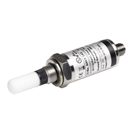
Michell representative (for Michell Instruments’ contact information go to www.michell.com). Features The SF72 dew-point transmitter is a continuous on line 4-20mA transmitter for the measurement of moisture content in air and other non-corrosive gases. The key features are: •... -
Page 10: Installation
SF72 Transmitter User’s Manual INSTALLATION INSTALLATION Unpacking the Instrument On delivery, please check that all the following standard components are in the packing box: • SF72 Transmitter • Bonded Seal • Certifi cate of Calibration • Connector (for sensor/cable) Unpack the dew-point transmitter box as follows: “... -
Page 11: Preparation Of The Sensor Cable
The sensor cable is NOT supplied as standard. A cable can be obtained by contacting your local distributor or Michell Instruments (see www.michell.com for details). Cable connection to the SF72 transmitter is made via the removable connector. Removing the central screw enables the connector terminal block to be removed from the outer housing by using a small screwdriver to prise it clear. -
Page 12: Cable Connection
SF72 Transmitter User’s Manual INSTALLATION Cable Connection When installing the connector, and to ensure that full ingress protection is achieved, the securing screw (with the O-ring and washer) must be tightened to a minimum torque setting of 3.4 Nm (2.5 ft-lbs). The sensor cable used must be a minimum diameter of 4.6mm (0.2”). -
Page 13: Electrical Boundaries
The SF72 can be mounted either into a fl ow-through sensor sampling block (optional) or directly into a pipe or duct. It can be operated at pressures of up to 45 MPa (450 barg / 6500 psig) when fi... -
Page 14: Transmitter Mounting - Sample Block (Optional)
INSTALLATION 2.5.1 Transmitter Mounting - Sample Block (Optional) (Applicable to the SF72 ⅝” -18 UNF and G½ BSP versions ONLY) The following procedure must be carried out by a qualifi ed installation engineer. To mount the transmitter into the sensor block (preferred method), proceed as follows, refer to Figure 7. -
Page 15: Transmitter Mounting - Direct Pipeline Connection
SF72 Transmitter User’s Manual INSTALLATION 2.5.2 Transmitter Mounting - Direct Pipeline Connection The transmitter may be directly mounted into a pipe or duct as shown in Figure 8. CAUTION: Do not mount the transmitter too close to the bottom of a bend where any condensate in the pipeline might collect and saturate the probe. -
Page 16: Operation
fi lter, as a minimum level of protection. For more demanding applications Michell Instruments offers a range of sampling systems (for more information contact www.michell.com). -
Page 17: Maintenance
Routine maintenance of the SF72 is confi ned to regular re-calibration by exposure of the SF72 to sample gases of known moisture content to ensure that the stated accuracy of the SF72 is maintained. Calibration services traceable to the UK National Physical Laboratory (NPL) and the US National Institute of Standards and Technology (NIST) are provided by Michell Instruments. -
Page 18: O-Ring Replacement
SF72 Transmitter User’s Manual MAINTENANCE O-Ring Replacement Do not touch the fi lter with bare hands Identify the O-ring to be removed, as shown below. BS116 (3/4” x 3/32”) viton, 75 shore Carefully slide tweezers, thin bladed screwdriver or a blunt needle under the outer edge of the O-ring. -
Page 19: Appendix A Technical Specifi Cations
SF72 Transmitter User’s Manual APPENDIX A Appendix A Technical Specifi cations Michell Instruments... -
Page 20: Dimensions
SF72 Transmitter User’s Manual APPENDIX A Appendix A Technical Specifi cations Performance Measurement Range (Dew -60 to +60ºCdp (-76 to +140ºFdp) Point) Accuracy (Dew Point) ±2ºCdp (±3.6ºFdp) Repeatability ±0.2ºCdp (±0.36ºCdp) Long Term Stability <1% per annum Calibration Traceable 8-point calibration certifi cate Electrical Specifi... -
Page 21: Figure 12 Dimensions - Sf72 2-Wire
SF72 Transmitter User’s Manual APPENDIX A Dimensions SENSOR G1/2” BSP Bonded Seal 132mm (5.19”) 46mm 45mm (1.81”) (1.77”) 27mm ø27mm 10mm (1.06”) (0.39”) (1.06”) G1/2” BSP ø28.65 x 2.61mm 10mm (ø1.12 x 0.10”) (0.39”) SENSOR 3/4” - 16 UNF O-Ring 132mm (5.19”) -
Page 22: Appendix B Quality, Recycling & Warranty Information
SF72 Transmitter User’s Manual APPENDIX B Appendix B Quality, Recycling & Warranty Information 97325 Issue 4, May 2018... - Page 23 SF72 Transmitter User’s Manual APPENDIX B Appendix B Quality, Recycling & Warranty Information Michell Instruments is dedicated to complying to all relevant legislation and directives. Full information can be found on our website at: www.michell.com/compliance This page contains information on the following directives: •...
-
Page 24: Appendix C Return Document & Decontamination Declaration
SF72 Transmitter User’s Manual APPENDIX C Appendix C Return Document & Decontamination Declaration 97325 Issue 4, May 2018... - Page 25 Has the equipment been cleaned and decontaminated? NOT NECESSARY Michell Instruments will not accept instruments that have been exposed to toxins, radio-activity or bio-hazardous Work will not be carried out on any unit that does not have a completed decontamination declaration.
- Page 26 SF72 Transmitter User’s Manual NOTES: Michell Instruments...
- Page 28 http://www.michell.com...
Need help?
Do you have a question about the SF72 and is the answer not in the manual?
Questions and answers