Table of Contents
Advertisement
Quick Links
2562248 REV H1 0520
Safety Message to Installers and Operators of Warning Lights
People's lives depend on your proper installation and operation of Federal Signal products. It is important
to read and follow all instructions shipped with this product and the original product. Listed below are some
other important safety instructions and precautions you should follow:
• To properly install a light assembly, you must have a good understanding of automotive electrical
procedures and systems, along with proficiency in the installation and use of safety warning equipment.
• When installing equipment or wiring inside airbag equipped vehicles, the installer MUST ensure that
the equipment or wiring is installed ONLY in areas recommended by the vehicle manufacturer. Failure
to observe this warning will reduce the effectiveness of the airbag, damage the airbag, or potentially
damage or dislodge the equipment, causing serious injury or death.
• When drilling into a vehicle structure, ensure that both sides of the surface are clear of anything that
could be damaged.
• A light system is a high current device. In order for it to function properly, a separate ground connection
must be made. If practical, it should be connected to the negative battery terminal. At a minimum, it may
be attached to a solid metal body or chassis part that will provide an effective ground path as long as the
light system is to be used.
• Locate the light system controls so the VEHICLE and CONTROLS can be operated safely under all
driving conditions.
• If a vehicle seat is temporarily removed, verify with the vehicle manufacturer if the seat needs to be
recalibrated for proper airbag deployment.
• This product contains high intensity LED devices. To prevent eye damage, DO NOT stare into the light
beam at close range.
• Frequently inspect the light system to ensure that it is operating properly and is securely attached to the
vehicle.
• File these instructions in a safe place and refer to them when maintaining and/or reinstalling the product.
Failure to follow all safety precautions and instructions may result in property damage, serious injury, or
death.
Product Overview
The Serial Interface Module is a device to communicate with Convergence Network controlled light bars.
To minimize the number of discrete wires to the light bar, control lead functions are wired to the Interface
Module. The information is converted to a digital format and communicated to the light bar via the serial
communication cable. Light bar patterns can be changed through the programming procedure.
Control leads can also activate an Internal SignalMaster
SignalMaster controller can link with the Interface Module and directly control SignalMaster operation.
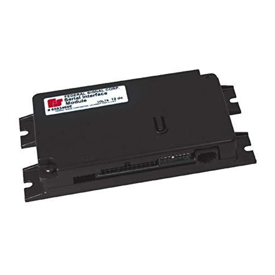
The Serial Interface Module can be identified by part number 8583446 on the nameplate located on the
top of the housing. A 3-foot-long, 24-conductor, control-link cable harness is also provided for external
connection (J1) to the Interface Module.
Installation and Programming Instructions
for the Serial Interface Module
controller. If preferred, an external Federal Signal
™
Advertisement
Table of Contents

Related Manuals for Federal Signal Corporation Serial Interface Module


Summary of Contents for Federal Signal Corporation Serial Interface Module
- Page 1 SignalMaster controller can link with the Interface Module and directly control SignalMaster operation. The Serial Interface Module can be identified by part number 8583446 on the nameplate located on the top of the housing. A 3-foot-long, 24-conductor, control-link cable harness is also provided for external...
- Page 2 Before permanently installing the Serial Interface Module (described on page 8), test and program the light bar. Each mode patterns is programmed independently. If you want to program the light bar after you connect a progressive slide switch, the programming sequence must be MODE 3, MODE 2, MODE 1, and then INTERSECTION.
- Page 3 Installation and Programming Instructions for the Serial Interface Module 4. Connect the fuse end of the white wire from the supplied J1 cable harness as close as possible to switched ignition power. Power should also be present in the cranking start position.
- Page 4 Installation and Programming Instructions for the Serial Interface Module Programming the Flash Patterns Before programming CUT OFF, program the light bar flash patterns. To access flash patterns, ensure that SW2 Switch 1 is OFF. NOTE: Cruise lights are also available in MODES 1 and 2.
- Page 5 FRONT and REAR CUT OFF can be programmed to activate when 12 Vdc is removed from the respective control leads. To change the active states for FRONT and REAR CUT OFF, remove ignition power to the Serial Interface Module. Refer to Table 1 on page 3 for the DIP switch settings. Programming the Intersection Function The INTERSECTION function can be programmed to be activated for HIGH (+ BAT maintained), or TAP II (+BAT, push on/push off), or 8-SECOND TIMEOUT (activated by +BAT).
- Page 6 Installation and Programming Instructions for the Serial Interface Module Light Bar Functions Activated via the CAT5 Cable (Excluding SignalMaster) LIGHT HAZARD: To be an effective warning device, this product produces bright light that can be hazardous to your eyesight when viewed at a close range. Do not stare directly into this lighting product at a close range, or permanent damage to your eyesight may occur.
- Page 7 Installation and Programming Instructions for the Serial Interface Module Steady Burn Red When the light bar is equipped with a STEADY BURN RED LED module, applying 12 Vdc to the control lead causes that module to operate when any mode input is selected.
- Page 8 The SCENE LIGHT, RIGHT option is available only in light bars with SpectraLux Technology (Valor and Vision SLR). To use the SCENE LIGHT, RIGHT with the Serial Interface Module, you must place SW2 Switch 3 in the down position (ON). The LIGHT BAR TEST is unavailable with this switch setting.
- Page 9 Failure to follow this warning cause serious injury or death. To wire the Serial Interface Module to power and ground: 1. Connect the white wire from the supplied J1 cable harness on the Interface Module to a 1 A fuse.
- Page 10 Installation and Programming Instructions for the Serial Interface Module Figure 4 SignalMaster control functions wired to 12 Vdc for Internal Control (factory default) J1 Cable to Power (+12 Vdc) Serial Interface Module Black/Red Mode 3 Blue/White Mode 2 Blue Mode 1...
- Page 11 Installation and Programming Instructions for the Serial Interface Module Figure 5 SignalMaster control functions wired to 12 Vdc for External Control J1 Cable to Power (+12 Vdc) Serial Interface Module Black/Red Mode 3 Mode 2 Blue/White Blue Mode 1 Steady Burn...
- Page 12 This product is subject to and covered by a limited warranty, a copy of which can be found at www.fedsig.com/SSG-Warranty. A copy of this limited warranty can also be obtained by written request to Federal Signal Corporation, 2645 Federal Signal Drive, University Park, IL 60484, email to info@fedsig.com or call +1 708-534-3400.
Need help?
Do you have a question about the Serial Interface Module and is the answer not in the manual?
Questions and answers