Advertisement
Quick Links
INSTALLATION AND MAINTENANCE INSTRUCTIONS
APA151 Annunciator
with Piezo Alert
SPECIFICATIONS
Dimensions:
Weight:
Electrical Requirements
Voltage:
Operational Voltage:
Maximum Operating Current:
Connections:
UL Reverberant Room:
Standard Operating Temperature:
Humidity Range:
NOTICE: These models were only tested at the 16-33 Volt DC limits. This does
not include the 80% low-end or 110% high-end voltage limits. This manual
shall be left with the owner/user of this equipment.
GENERAL INFORMATION
The National Fire Protection Association (NFPA) has published codes, stan-
dards, and recommended practices for the installation and use of this product.
It is recommended that the installer be familiar with these requirements, with
local codes, and any special requirements of the local authority having juris-
diction. For further information, consult NFPA 72 and 90A requirements.
The System Sensor APA151 annunciator with piezo alert is an audible signal
appliance for fire alarm service. It is intended for use in System Sensor 4-wire
conventional duct smoke detector applications without a system control panel
to comply with NFPA 90A.
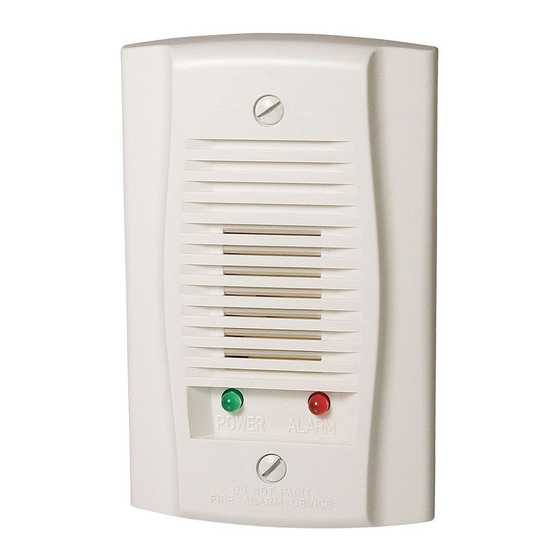
The APA151 provides a red alarm LED, with an audible annunciation of an
alarm signal, and a green power LED.
FIGURE 1:
APA151 CONTENTS
1 APA151 annunciator with piezo alert
1 screw pack (containing two mounting screws)
4.6˝ L × 2.9˝ W × .45˝ D
.17 lbs.
Regulated 24VDC
16–33 VDC
30mA
#6 binding head screws, 12 AWG to 18 AWG wire
81 dBA min. @ 10 ft.
0°C to 49°C (32°F to 120°F)
10% to 93% non-condensing
A0360-01
3825 Ohio Avenue, St. Charles, Illinois 60174
INSTALLATION
Wire the APA151 as shown in Figure 1 thru Figure 3 depending on what duct
smoke detector is being utilized. Limit wire runs to 25 ohms or less per inter-
connecting wire.
Secure the APA151 to the single gang box using the two screws provided, or
directly to the wall or ceiling.
OPERATIONAL TEST
Consult the wiring diagrams below to insure proper wiring to the APA151.
Supply power to the duct smoke detector. Visually check the supervisory LED
(green) to make sure it is operational.
Put the detector into alarm state. The alarm LED (red) will light, and the piezo
horn will sound. Reset the detector.
FIGURE 2: WIRING DIAGRAM FOR D4120 TO APA151:
APA151/451
COMMON
1
(RED LED) ALARM
2
(GREEN LED) POWER
3
NOTE: WIRING DIAGRAM SHOWN IS FOR D4120 4-WIRE DUCT SMOKE
DETECTOR SYSTEM EQUIPPED WITHOUT A CONTROL PANEL.
NOTE: A TROUBLE CONDITION IS INDICATED
BY LOSS OF GREEN LED
FIGURE 3: WIRING DIAGRAM FOR D4120/DH100ACDC TO APA151:
4-Wire Wiring to APA151
DH100ACDC
Alarm Signal
15
Aux. Power +
19
Sup. N. O.
14
Sup. COM
3
Aux. Power –
20
NOTE: Wiring diagram shown is for DH100ACDC 4-wire duct
smoke detector system equipped without a control panel.
1
1-800-SENSOR2, FAX: 630-377-6495
www.systemsensor.com
D4120
10
FIELD
7
9
INSTALLED
18
AUX OUT +
JUMPER
19
8
20
AUX OUT –
17
1
6
12
16
15
ALARM
14
SUP, NO
11
R TEST
SUP, C
3
2
R RESET
13
+
ACC +
5
–
ACC –
4
H0584-02
APA151
Alarm
(Red LED)
Power
(Green LED)
Common
H0581-01
I56-2964-004
06-10
Advertisement

Subscribe to Our Youtube Channel
Related Manuals for System Sensor APA151


Summary of Contents for System Sensor APA151
- Page 1 NOTICE: These models were only tested at the 16-33 Volt DC limits. This does not include the 80% low-end or 110% high-end voltage limits. This manual Wire the APA151 as shown in Figure 1 thru Figure 3 depending on what duct shall be left with the owner/user of this equipment.
- Page 2 TX 79936, USA. Please include a note describing the malfunction and suspected cause System Sensor warrants its enclosed product to be free from defects in materials and of failure. The Company shall not be obligated to replace units which are found to be...
Need help?
Do you have a question about the APA151 and is the answer not in the manual?
Questions and answers