Advertisement
Installation AND MAINTENANCE INSTRUCTIONS
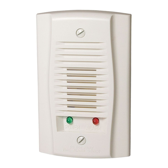
APA151 Annunciator
with Piezo Alert
Specifications
Dimensions:
Weight:
Electrical Requirements:
Voltage:
Operational Voltage:
Maximum Operating Current:
Connections:
UL Reverberant Room:
Standard Operating Temperature:
Humidity Range:
NOTICE: These models were only tested at the 16-33 Volt
DC limits. This does not include the 80% low-end or 110%
high-end voltage limits. This manual shall be left with the
owner/user of this equipment.
General Information
The National Fire Protection Association (NFPA) has pub-
lished codes, standards, and recommended practices for the
installation and use of this product. It is recommended that
the installer be familiar with these requirements, with local
codes, and any special requirements of the local authority
having jurisdiction. For further information, consult NFPA
72 and 90A requirements.
The System Sensor APA151 annunciator with piezo alert
is an audible signal appliance for fire alarm service. It is
intended for use in System Sensor 4-wire conventional duct
smoke detector applications without a system control panel
to comply with NFPA 90A.
The APA151 provides a red alarm LED, with an audible an-
nunciation of an alarm signal, and a green power LED.
D640-02-00
4.6˝ L × 2.9˝ W × .45˝ D
.17 lbs.
Regulated 24VDC
16–33 VDC
30mA
#6 binding head screws, 12 AWG to 18 AWG wire
81 dBA min. @ 10 ft.
0°C to 49°C (32°F to 120°F)
10% to 93% non-condensing
Figure 1:
1
3825 Ohio Avenue, St. Charles, Illinois 60174
1-800-SENSOR2, FAX: 630-377-6495
www.systemsensor.com
A0360-01
I56-2964-002
Advertisement
Table of Contents

Related Manuals for System Sensor APA151


Summary of Contents for System Sensor APA151
- Page 1 System Sensor 4-wire conventional duct smoke detector applications without a system control panel to comply with NFPA 90A. A0360-01 The APA151 provides a red alarm LED, with an audible an- nunciation of an alarm signal, and a green power LED. D640-02-00 I56-2964-002...
-
Page 2: Operational Test
Installation the supervisory LED (green) to make sure it is operational. Wire the APA151 as shown in Figure 2. Limit wire runs to Put the detector into alarm state. The alarm LED (red) will 25 ohms or less per interconnecting wire.
Need help?
Do you have a question about the APA151 and is the answer not in the manual?
Questions and answers