Advertisement
Quick Links
INSTALLATION AND MAINTENANCE INSTRUCTIONS
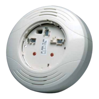
B200SRA
Intelligent Sounder Base
Specifications
Base Diameter:
Base Height (less sensor):
Weight:
Operating Temperature Range:
Operating Humidity Range:
External Supply Electrical Ratings
External Supply Voltage:
Standby Current:
Alarm Current:
SLC Electrical Ratings
SLC Operating Voltage:
SLC Standby Current:
Sound Output
BEFORE INSTALLING
Please read the System Sensor Smoke Detector Application Guide, which
provides detailed information on sensor spacing, placement, zoning, wiring,
and special applications. Copies of this manual are available from System
Sensor. CAN/ULC-S524 guidelines should be observed.
NOTICE: This manual should be left with the owner/user of this equipment.
IMPORTANT: The detector used with this base must be tested and main-
tained regularly following CAN/ULC-S536 requirements. The detector should
be cleaned at least once a year.
GENERAL DESCRIPTION
The B200SRA sounder base is used with System Sensor 200-Series sensor
heads or equivalent. Refer to the appropriate manual for more information on
sensors.
The B200SRA sounder base was designed specifically to meet the needs of
dwelling unit applications. It offers maximum flexibility in configuration and
operation to meet or exceed the requirements of CAN/ULC-S525 and CAN/
ULC-S529.
The sounder base is capable of producing either the distinctive three-pulse
temporal pattern (ANSI Temporal 3) fire alarm signal now required by NFPA
72 for commercial and residential applications or a continuous tone by simply
removing the included jumper from the device. Additionally, the B200SRA is
designed to be compatible with existing installations of B501-Series sounder
bases.
The sounder base is intended for use with intelligent systems. The sounder
base requires an external 24 VDC power supply. The connections for the
external power supply and the communication loop are isolated to prevent
electrical interaction between them. Refer to the panel manual for maximum
allowable number of units per loop.
NOTE: When not used as a supplementary evacuation system, the external
24 VDC supply shall be treated as a component of the main power supply
system and shall fall under the requirements of the main power supply sys-
tem per ULC.
WIRING GUIDELINES
All wiring must be installed in compliance with the Canadian Electrical Code
SS-450-001
6.875" (17.46 cm)
2.0" (5.08 cm)
0.50 lb. (227 gm)
32° to 150°F (0° to 66°C)
10% to 93% relative humidity (non-condensing)
16 to 33 VDC (VFWR)
500 μA maximum
40mA max(DC), 70mA maxFWR
15 to 32 VDC
300 μA maximum
Greater than 85 dBA minimum measured in a ULC anechoic room at 10 feet, 24 Volts (in continuous tone)
6581 Kitimat Road, Unit 6, Mississauga, Ontario L5N-3T5
and the local codes having jurisdiction and must not be of such length or wire
size which would cause the base to operate outside of its published specifica-
tions. The conductors used to connect smoke sensors to control panels and
accessory devices should be color coded to reduce the likelihood of wiring
errors. Improper connections can prevent a system from responding properly
in the event of a fire.
Wire sizes up to 12 AWG (2.5 mm
base will be shipped with the screw terminals set for 14 AWG wiring. If 12
AWG wire is to be used, back out the screws to allow the wire to fit beneath
the clamping plates. For best system performance, the power (+ and -) wires
and the communication circuit wires should be twisted air or shielded cable
installed in a separate grounded conduit to protect the communication loop
from electrical interference.
Make wire connections by stripping about 3/8" of insulation from the end of
the wire. Then, slide the bare end of the wire under the appropriate clamping
plate (See Figure 1), and tighten the clamping plate screw. Do NOT loop the
wire under the clamping plate (See Figure 2) The wiring diagram for a typical
2-wire intelligent system is shown in Figure 4.
For system monitoring - for terminals 4 and 5, do not use looped wire under
terminals. Break wire run as shown in Figure 2 to provide monitoring of connec-
tions.
1
1-800-SENSOR2, FAX: 905-812-0771
www.systemsensor.ca
2
) may be used with the base. The sounder
CAUTION
I56-3470-000
Advertisement

Related Manuals for System Sensor B200SRA


Summary of Contents for System Sensor B200SRA
- Page 1 Make wire connections by stripping about 3/8” of insulation from the end of The B200SRA sounder base was designed specifically to meet the needs of the wire. Then, slide the bare end of the wire under the appropriate clamping dwelling unit applications.
- Page 2 External Supply Negative (-) Sounder Base Interconnect MOUNTING Mount the B200SRA mounting plate directly to an electrical box. The plate will mount directly to 4” square (with or without plaster ring), 4” octagon, 3 1/2” C0891-03 octagon, single gang and double gang junction boxes.
- Page 3 DETECTOR ACTIVATES SOUNDER BASE(S) ULC has approved grouping for up to six B200SRA sounder bases. When wired as a group, any detector in the group that has been activated by the panel will cause other B200SRA units in the group to sound. This type of “local” grouping is accomplished by wiring the grouped devices together using terminal 6, Sounder Base Interconnect, as shown in the diagram.
- Page 4 THREE-YEAR LIMITED WARRANTY to: System Sensor, Returns Department, RA #__________, 6581 Kitimat Road, Unit 6, System Sensor warrants its enclosed smoke detector base to be free from defects in Mississauga, Ontario L5N-3T5. Please include a note describing the malfunction and materials and workmanship under normal use and service for a period of three years suspected cause of failure.
Need help?
Do you have a question about the B200SRA and is the answer not in the manual?
Questions and answers