Advertisement
Quick Links
INSTALLATION AND MAINTENANCE INSTRUCTIONS
SpectrAlert Strobe and
Horn/Strobe
For use with the following 24-volt models:
Strobes:
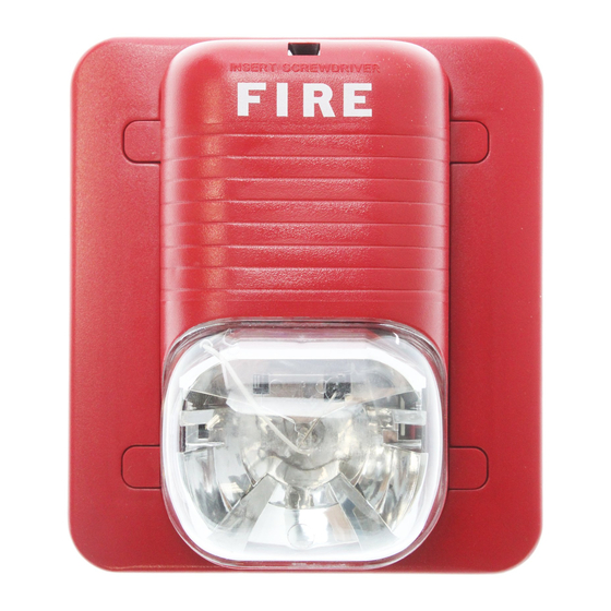
S2475RLP, S2475ALP, S2475GLP, S2475BLP
Horn/Strobes:
P2475RLP, P2475ALP, P2475GLP, P2475BLP
Lens colors: "RLP" for Red, "ALP" for Amber, "GLP" for Green, "BLP" for Blue
The "P" suffix indicates no markings on the housing; add suffix "W" for white housing models.
The Products to which this manual applies may be covered by one or more of the following
U.S. Patent numbers: 5,914,665; 5,850,178; 5,593,569; 5,598,139; 6,049,446; 6,133,843
Specifications
Voltage Range:
Strobes and Horn/Strobes: 24-volt models – 20 to 30 volts
(with MDL module):
Flash Rate:
Operating Temperature:
Light Output:
Sound Output:
Listings:
General Description
The SpectrAlert series notification appliances are designed to meet the
requirements of NFPA, The National Fire Alarm Code, and UL. Also, check
with your local Authority Having Jurisdiction for other codes or standards
that may apply.
This SpectrAlert S2475XXX Series Strobe and P2475XXX Series style
Horn/Strobe can be installed in systems using 24-volt panels having DC or
full-wave rectified (FWR) power supplies. The models can also be installed
in systems requiring synchronization (module MDL required) or systems
that do not require synchronization (no module required).
NOTICE: This manual shall be left with the owner/user of this equipment.
Fire Alarm System Considerations
Temporal and Non-Temporal Coded Signals:
The American National Standards Institute and the National Fire Alarm
Code require that all horns used for building evacuation installed after July
1, 1996, must produce Temporal Coded Signals.
Signals other than those used for evacuation purposes do not have to pro-
duce the Temporal Coded Signal. Temporal coding is accomplished by inter-
rupting a steady sound in the following manner:
1
1
1
/
Sec.
/
Sec.
/
Sec.
2
2
2
On
Off
On
D900-25-00
DC or Full-Wave Rectified
24-volt models – 21 to 30 volts
NOTE: Combo unit will operate on walk tests with on-time durations of 1 sec. or greater.
1 Flash Per Second
32° F to 120° F (0° C to 49° C)
75 candela
Sound output levels are established at Underwriters Laboratories in their reverberant room. Always use the
sound output specified as UL Reverberant Room when comparing products.
UL S4011 (Horn/Strobe), UL S3593 (Strobe)
1
1
1
/
Sec.
/
Sec.
1
/
Sec.
Repeats
2
2
2
Off
On
Off
Power Supply Considerations
Panels typically supply DC filtered voltage or FWR (full-wave rectified)
voltage. The system design engineer must calculate the number of units
used in a zone based on the type of panel supply. Be certain the sum of
all the device currents do not exceed the current capability of the panel.
Calculations are based on using the device current found in the subsequent
charts and must be the current specified for the type of panel power sup-
ply used.
Wire Sizes
The designer must be sure that the last device on the circuit has sufficient
voltage to operate the device within its rated voltage. When calculating
the voltage available to the last device, it is necessary to consider the volt-
age drop due to the resistance of the wire. The thicker the wire, the less
the voltage drop. Generally, for purposes of determining the wire size nec-
essary for the system, it is best to consider all of the devices as "lumped"
on the end of the supply circuit (simulates "worst case").
Typical wire size resistance:
18 AWG solid:
Approximately 8 ohms/1,000 ft.
16 AWG solid:
Approximately 5 ohms/1,000 ft.
14 AWG solid:
Approximately 3 ohms/1,000 ft.
12 AWG solid:
Approximately 2 ohms/1,000 ft.
Example: Assume you have 10 devices on a zone and each requires 50
mA average and 2000 Ft. of 14 AWG wiring (total length=outgoing
+return). The voltage at the end of the loop is 0.050 amps per device x
10 devices x 3 ohms/1,000 ft. x 2000 ft =3 volts drop.
The same number of devices using 12 AWG wire will produce only 2 volts
drop. The same devices using 18 AWG wire will produce 8 volts drop.
Consult your panel manufacturer's specifications, as well as SpectrAlert's
operating voltage range to determine acceptable voltage drop.
Note: If class "A" wiring is installed, the wire length may be up to 4 times
the single wire length in this calculation.
1
A Division of Pittway
3825 Ohio Avenue, St. Charles, Illinois 60174
1-800-SENSOR2, FAX: 630-377-6495
www.systemsensor.com
I56-0981-000R
Advertisement

Related Manuals for System Sensor SpectrAlert Series


Summary of Contents for System Sensor SpectrAlert Series
- Page 1 UL S4011 (Horn/Strobe), UL S3593 (Strobe) General Description Power Supply Considerations The SpectrAlert series notification appliances are designed to meet the Panels typically supply DC filtered voltage or FWR (full-wave rectified) requirements of NFPA, The National Fire Alarm Code, and UL. Also, check voltage.
- Page 2 Current Draws Strobe: AVERAGE CURRENT (mA) PEAK CURRENT (mA) IN RUSH CURRENT (mA) 24V Models 24V Models 24V Models DC FWR DC FWR DC DC FWR DC FWR DC DC FWR DC FWR DC 169 220 140 191 115 174 460 560 450 570 420 620 190 230 220 290 290 370 Horn/Strobe:...
- Page 3 The strobe must have an unin- ery or music appliances that may prevent alert persons from hearing the terrupted source of power in order to operate correctly. System Sensor rec- alarm. The horn may not be heard by persons who are hearing impaired.
- Page 4 4. Press into skirt; unit will make a “click” when it has locked into place. (Note: Strobe and skirt may also be mounted to a 2-inch box using screws B instead of screws A.) D900-25-00 I56-0981-000R © System Sensor 2001...
Need help?
Do you have a question about the SpectrAlert Series and is the answer not in the manual?
Questions and answers