Advertisement
Quick Links
INSTALLATION AND MAINTENANCE INSTRUCTIONS
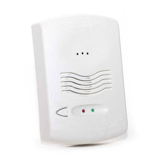
CO1224A
Carbon Monoxide Alarm
Specifications
Electrical Specifications
System Voltage
Nominal:
Min:
Max:
Avg. Standby Current:
Max Alarm Current:
Alarm Contact Ratings:
Trouble Contact Ratings:
Audible Signal (temp 4 tone):
Max. Start-up Capacitance:
NOTICE: This manual shall be left with the owner/user of this
equipment.
WARNING: This product is intended for use in ordinary indoor
locations of dwelling units, including homes, residential
buildings, hotels, schools, dormitories, and day care centers. It is
not intended for use in industrial factories or commercial parking
garages.
General Description
• Listed to CSA 6.19-01
• Six-wire, system monitored or stand-alone operation
• Local sounder
• Low current draw
• Alarm relay, Form C
• Trouble relay, Form A
• Dual LED's
• Test/Hush button
• SEMS wiring terminals
• Mount to single gang electrical box or surface mount to wall
or ceiling
• Optional drywall anchors included
Figure 1. Alarm Location Diagram:
BEDROOM
TO
BR
BEDROOM
BEDROOM
KITCHEN
LIVING
ROOM
BASEMENT
–
CARBON MONOXIDE ALARM
LOCATION FOR MULTI-LEVEL RESIDENCE
12/24 VDC
10 VDC
33 VDC
20 mA
40 mA (75 mA test)
30 VDC @ 0.5 A
30 VDC @ 0.5 A
85 dBA min. in alarm (at 10ft)
20 uF
GARAGE
CLOSED
DOOR
S0295-00
6581 Kitimat Rd., Unit #6, Mississauga, Ontario, L5N 3T5
Physical Specifications
Operating Temperature Range:
Operating Humidity Range:
Length:
Width:
Height:
Weight:
Wire Gauge Acceptance:
Table 1. Operation Modes:
OPERATION
GREEN
MODE
LED
Normal
Blink 1 per
(standby)
minute
Alarm
OFF
Alarm Test
OFF
Blink 1 per
RealTest Mode
second (waiting
for gas entry)
CO End of Life
OFF
*Temp 4 pattern is repeated pattern of four short indications
followed by a five second pause.
When the unit has been in alarm for 30 minutes the alarm signal
will be given once every minute.
If ambient conditions return to normal, the unit will self-restore
out of alarm and into Normal (standby) mode.
Hush feature: If required, the audible alarm can be silenced for
5 minutes by pushing the button marked "Test/Hush". The red
alarm light will continue to flash in temp-4 pattern. If carbon
monoxide is still present after the 5 minute hush period, the
audible alarm will sound. The hush facility will not operate at
levels above 350 ppm (parts per million) carbon monoxide.
Trouble feature: When the sensor supervision is in a trouble
condition (such as a sensor that has been tampered with), the
alarm will sound a trouble signal every 30-60 seconds and the
trouble contact will open . The alarm must then be replaced.
End of Life Timer feature: When the alarm has reached the end of
its life, the trouble signal will sound every 30-60 seconds and the
trouble contact will open. This indicates that the CO sensor inside
the alarm has passed the end of its life and must be replaced.
This alarm's lifespan is approximately ten years from the date of
manufacture. Refer to Alarm Replacement on page 3.
Refer to Figure 4 for wiring of the alarm and trouble relays.
1
1-800-SENSOR2, FAX: 905-812-0771
www.systemsensor.ca
0° to 40°C (32° to 104°F)
22 – 90% %RH
5.1˝
3.3˝
1.3˝
7 oz
14-22 AWG
RED
SOUNDER
LED
OFF
OFF
Temp 4* pattern
Temp 4* pattern
Temp 4 pattern
Temp 4 pattern
Temp 4 pattern
OFF (Red after
(after CO is
CO is sprayed)
sprayed)
Chirp every
OFF
30-60 seconds
I56-3247-006
10-28
Advertisement

Subscribe to Our Youtube Channel
Related Manuals for System Sensor CO1224A


Summary of Contents for System Sensor CO1224A
-
Page 1: Specifications
INSTALLATION AND MAINTENANCE INSTRUCTIONS CO1224A 6581 Kitimat Rd., Unit #6, Mississauga, Ontario, L5N 3T5 1-800-SENSOR2, FAX: 905-812-0771 Carbon Monoxide Alarm www.systemsensor.ca Specifications Electrical Specifications Physical Specifications Operating Temperature Range: 0° to 40°C (32° to 104°F) System Voltage Nominal: 12/24 VDC Operating Humidity Range: 22 –... -
Page 2: Installation Guidelines
The CO1224A can be wall- or ceiling-mounted: CAUTION 1. To a single gang box, or Airborne dust particles can enter the alarm. System Sensor 2. Direct mount to wall or to ceiling using drywall fasteners. recommends the removal of alarms before beginning construction or any other dust producing activity. - Page 3 Also young children and pets may be the first to be affected. Functional Gas Test Per CSA 6.19-01 the CO1224A has been tested to the following NOTE: Check with local codes and the AHJ to determine whether sensitivity limits.
- Page 4 − shall not be connected to a zone that signals a fire condition * Per NFPA 720 section 5.3.7, do not connect the CO1224A on a zone with other fire or intrusion initiating devices - i.e. do not connect on...
Need help?
Do you have a question about the CO1224A and is the answer not in the manual?
Questions and answers