Table of Contents
Advertisement
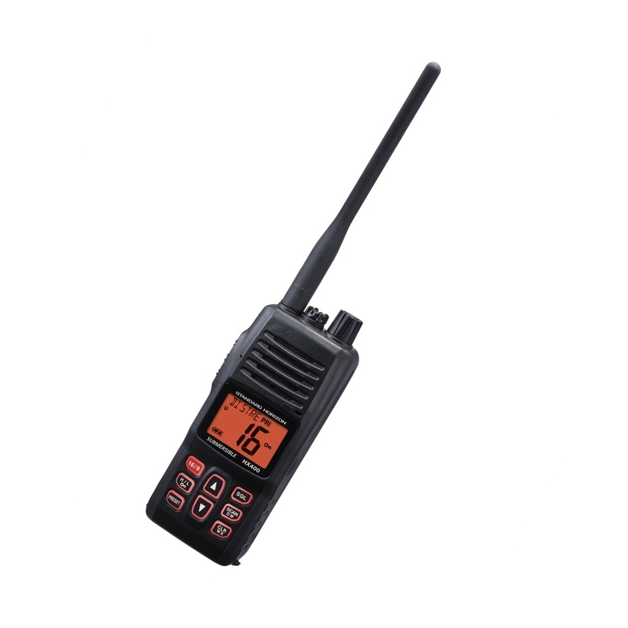
VHF FM Marine Transceiver
HX400
SERVICE MANUAL
Introduction
This manual provides the technical information necessary for servicing
the HX400 Transceiver.
Servicing this equipment requires expertise in handing surface-mount
chip components. Attempts by non-qualified persons to service this
equipment may result in permanent damage not covered by the war-
ranty, and may be illegal in some countries.
Two PCB layout diagrams provided for each double-sided board in
this transceiver. Each side of the board is referred to by the type of the
majority of components installed on that side ("Side A" or "Side B").
In most cases one side has only chip components, and the other has
either a mixture of both chip and leaded components (trimmers, coils,
electrolytic capacitors, ICs, etc.), or leaded components only.
While we believe the information in this manual to be correct, YAESU
assumes no liability for damage that may occur as a result of typo-
graphical or other errors that may be present. Your cooperation in
pointing out any inconsistencies in the technical information would be
appreciated.
Contents
Exploded View & Miscellaneous Parts
Board Unit (Schematics, Layouts & Parts)
MAIN Unit
Important Note
1) This transceiver was assembled using Pb (lead) free solder, based
on the RoHS specification.
Only lead-free solder (Alloy Composition: Sn-3.0Ag-0.5Cu)
should be used for repairs performed on this apparatus. The solder
stated above utilizes the alloy composition required for compliance
with the lead-free specification, and any solder with the above al-
loy composition may be used.
2) Risk of explosion if battery is replaced by an incorrect type. Dis-
pose of used batteries according to the instructions.
EM039N95D
©2018 YAESU MUSEN CO., LTD.
Advertisement
Table of Contents

Related Manuals for Standard Horizon HX400


Summary of Contents for Standard Horizon HX400
- Page 1 ©2018 YAESU MUSEN CO., LTD. Introduction This manual provides the technical information necessary for servicing the HX400 Transceiver. Servicing this equipment requires expertise in handing surface-mount chip components. Attempts by non-qualified persons to service this equipment may result in permanent damage not covered by the war- ranty, and may be illegal in some countries.
-
Page 2: Specifications
700 mW @16 Ω for 10 % THD (@7.4 V) AF Output (External SP): 350 mW @8 Ω for 10 % THD (@7.4 V) Performance specifications are nominal, unless otherwise indicated, and are subject to change without no- tice. Measured in accordance with TIA/EIA-603. Specifications HX400 Service Manual... -
Page 3: Exploded View
Important Note: To ensure the radio is water proof, make U44105001 PAN HEAD TAPTITE-B M2X5 sure the gasket is installed on the chassis correctly and U9900068 PAN HEAD TAPTITE-B M2X4NI#3 is not pinched when inserted into the front case. Exploded View HX400 Service Manual... - Page 4 Block Diagram Block Diagram HX400 Service Manual...
- Page 5 Alignment Introduction and Precautions Required Test Equipment RF Signal Generator with calibrated output lev- The HX400 has been carefully aligned at the fac- el at 200 MHz tory for performance across the specified VHF Avionics Radio Tester band. Realignment should therefore not be nec- ...
- Page 6 Set up the test equipment as shown below for transceiver alignment, apply 7.4 VDC power to the transceiver. Notes: signal levels in dB referred to in alignment are based on EMF (0 dBμ = 1.0 μV). Test Equipment Setup Alignment - 2 HX400 Service Manual...
- Page 7 “C”. 5. Set the RF Signal Generator output level 0 dBμV (with a standard FM modulation: ±3.0 kHz deviation @ 1 kHz) at 156.800 MHz. Alignment - 3 HX400 Service Manual...
- Page 8 2 seconds to save the Squelch Threshold level at band edge. the low band edge. 12. Press the [CLR(WX)] key to exit from this align- 12. Press the [CLR(WX)] key to exit from this align- ment item. ment item. Alignment - 4 HX400 Service Manual...
- Page 9 Squelch Tight level at the low band edge. edge. 12. Press the [CLR(WX)] key to exit from this align- 12. Press the [CLR(WX)] key to exit from this align- ment item. ment item. Alignment - 5 HX400 Service Manual...
- Page 10 5.0 W (±0.1W). 14. Press and hold the [H/L] key for 2 seconds to save thenew setting at the low band edge. 15. Press the [H/L] key to exit from this alignment item. Alignment - 6 HX400 Service Manual...
- Page 11 [p] or [q] key to adjust the deviation to 4.2 kHz (+0kHz/–0.1 kHz). 16. Press and hold the [H/L] key for 2 seconds to save the new setting at the band center. Alignment - 7 HX400 Service Manual...
- Page 12 5. Press and hold the [H/L] key for 2 seconds to save the new setting. 6. Press the [H/L] key to exit from this alignment item. Exit from the Alignment mode To exit from the Alignment mode, turn the trans- ceiver off. Alignment - 8 HX400 Service Manual...
- Page 13 MAIN Unit (Lot. -42) Circuit Diagram MAIN - 1 HX400 Service Manual...
- Page 14 MAIN Unit (Lot. -42) Parts Layout (Side A) MAIN - 2 HX400 Service Manual...
- Page 15 MAIN Unit (Lot. -42) Parts Layout (Side B) MAIN - 3 HX400 Service Manual...
- Page 16 MAIN Unit (Lot. 43-) Circuit Diagram MAIN - 4 HX400 Service Manual...
- Page 17 MAIN Unit (Lot. 43-) Parts Layout (Side A) MAIN - 5 HX400 Service Manual...
- Page 18 MAIN Unit (Lot. 43-) Parts Layout (Side B) MAIN - 6 HX400 Service Manual...
-
Page 19: Parts List
C 4070 CHIP CAP. 220pF GRM1552C1H221JA01D K22179713 C 4071 CHIP CAP. 0.01uF GRM155B11E103KA01D K22148834 C 4073 CHIP CAP. 0.001uF GRM155B11H102KA01D K22178809 C 4075 CHIP CAP. GRM1552C1H4R0BA01D K22178291 C 4076 CHIP CAP. 0.001uF GRM155B11H102KA01D K22178809 HX400 Service Manual MAIN - 6... - Page 20 C 4155 CHIP CAP. 0.01uF GRM155B11E103KA01D K22148834 C 4156 CHIP CAP. 150pF GRM1552C1H151JA01D K22178240 C 4157 CHIP CAP. 10pF GRM1552C1H100BA01D K22178297 C 4158 CHIP CAP. 10pF GRM1552C1H100BA01D K22178297 C 4158 CHIP CAP. GRM1552C1H8R0BA01D K22178295 HX400 Service Manual MAIN - 7...
- Page 21 C 4234 CHIP CAP. 150pF GRM1552C1H151JA01D K22178240 C 4235 CHIP CAP. 0.01uF GRM155B11E103KA01D K22148834 C 4236 CHIP CAP. 120pF GRM1552C1H121JA01D K22178238 C 4237 CHIP CAP. GRM155B31A105KE15D K22108809 C 4238 CHIP TA.CAP. 0.1uF TMCSA1V104MTRF K78160025 HX400 Service Manual MAIN - 8...
- Page 22 C 4314 CHIP CAP. 0.01uF GRM155B11E103KA01D K22148834 C 4315 CHIP CAP. 0.01uF GRM155B11E103KA01D K22148834 C 4316 CHIP CAP. 100pF GRM1552C1H101JA01D K22178236 C 4317 CHIP CAP. 100pF GRM1552C1H101JA01D K22178236 C 4318 CHIP CAP. 100pF GRM1552C1H101JA01D K22178236 HX400 Service Manual MAIN - 9...
- Page 23 HK1608 33NJ-T L1690522 L 4007 COIL 0.014uH ASs050425-14R0NJ L0022827 L 4009 M.RFC 0.047uH HK1608 47NJ-T L1690524 L 4010 COIL 0.039uH ASs030721-41R8NJ L0022587 L 4011 COIL 0.017uH ASs030616-17N L0022678 L 4012 COIL 0.017uH ASs030616-17N L0022678 HX400 Service Manual MAIN - 10...
- Page 24 Q 4039 TRANSISTOR DTC114TE TL G3070225 Q 4040 2SK508-T1B-A K52 G3805088B Q 4041 TRANSISTOR 2SC4215Y(TE85R.F) G3342157Y Q 4042 TRANSISTOR 2SC4227-T1 R32 G3342278B Q 4043 TRANSISTOR DTC114TE TL G3070225 Q 4044 TRANSISTOR 2SC4617 TL R G3346178R HX400 Service Manual MAIN - 11...
- Page 25 R 4057 CHIP RES. 1/16W 0.5% MCR01MZPD1002 J24189374 R 4058 CHIP RES. 1/16W RMC1/16S 331JTH J24189019 R 4059 CHIP RES. 100k 1/16W RMC1/16S 104JTH J24189049 R 4060 CHIP RES. 2.2k 1/16W RMC1/16S 222JTH J24189029 HX400 Service Manual MAIN - 12...
- Page 26 R 4134 CHIP RES. 1/16W 0.5% MCR01MZPD4702 J24189382 R 4135 CHIP RES. 4.7k 1/16W RMC1/16S 472JTH J24189033 R 4136 CHIP RES. 1/16W RMC1/16S 473JTH J24189045 R 4138 CHIP RES. 6.8k 1/16W RMC1/16S 682JTH J24189035 HX400 Service Manual MAIN - 13...
- Page 27 J24189005 R 4212 CHIP RES. 1/16W RMC1/16S 470JTH J24189009 R 4213 CHIP RES. 1/16W RMC1/16S 103JTH J24189037 R 4214 CHIP RES. 1/16W RMC1/16S 103JTH J24189037 R 4215 CHIP RES. 3.3k 1/16W RMC1/16S 332JTH J24189031 HX400 Service Manual MAIN - 14...
- Page 28 X 4003 TCXO 16.8MHz TTS14VSB-A3 16.80MHZ H9501100 XF4001 XTAL FILTER TF4-67EA1 67.65MHZ H1102399 XF4001 XTAL FILTER MFT67P 67.650MHZ H1102471 INTER CONNECTOR (LCD) RA1081000 LIGHT GUIDE (LCD) RA107890A REFLECTOR SHEET RA1089600 MIC HOLDER RUBBER RA1222500 HX400 Service Manual MAIN - 15...
- Page 29 MAIN Unit (Lot. 1-42) Parts List DESCRIPTION VALUE TOL. MFR'S DESIG YAESU P/N VERS. LOT SIDE LAY ADR MIC HOLDER RUBBER RA1194900 PAN HEAD TAPTITE-B M2X4NI#3 U9900068 HX400 Service Manual MAIN - 16...
- Page 30 C 5073 CHIP CAP. 0.001uF GRM155B11H102KA01D K22178809 C 5075 CHIP CAP. GRM1552C1H4R0BA01D K22178291 C 5076 CHIP CAP. 0.001uF GRM155B11H102KA01D K22178809 C 5077 CHIP CAP. 10uF GRM21BB31A106KE18L K22100808 C 5078 CHIP CAP. 10uF GRM21BB31A106KE18L K22100808 HX400 Service Manual MAIN - 17...
- Page 31 C 5159 CHIP CAP. 10pF GRM1552C1H100BA01D K22178297 C 5160 CHIP CAP. GRM1552C1H7R0BA01D K22178294 C 5161 CHIP CAP. 0.01uF GRM155B11E103KA01D K22148834 C 5163 CHIP CAP. 0.1uF GRM155B11A104KA01D K22108802 C 5164 CHIP CAP. 0.01uF GRM155B11E103KA01D K22148834 HX400 Service Manual MAIN - 18...
- Page 32 C 5240 CHIP CAP. 0.1uF GRM155B11A104KA01D K22108802 C 5241 CHIP TA.CAP. 3.3uF TMCMA1C335MTRF K78120021 C 5242 CHIP TA.CAP. 0.1uF TMCSA1V104MTRF K78160025 C 5244 CHIP CAP. 0.1uF GRM155B11A104KA01D K22108802 C 5245 CHIP CAP. 0.047uF GRM155B11A473KA01D K22108801 HX400 Service Manual MAIN - 19...
- Page 33 CHIP CAP. 0.01uF GRM155B11E103KA01D K22148834 C 5323 CHIP CAP. 0.01uF GRM155B11E103KA01D K22148834 C 5324 CHIP CAP. 0.01uF GRM155B11E103KA01D K22148834 CD5001 CERAMIC DISC JTBM450CX24 H7901530 CF5001 CERAMIC FILTER LTM450GW-A H3900573A CF5002 CERAMIC FILTER LTM450FW-A H3900572A HX400 Service Manual MAIN - 20...
- Page 34 L 5019 CHIP COIL 22uH NLV25T-220J-PF L1691440 L 5020 COIL 0.017uH ASs030616-17N L0022678 L 5021 M.RFC 0.22uH HK1608 R22J-T L1690940 L 5022 M.RFC 0.01uH HK1608 10NJ-T L1690516 L 5023 M.RFC 0.082uH HK1608 82NJ-T L1690527 HX400 Service Manual MAIN - 21...
- Page 35 DTC144EE TL G3070075 Q 5052 TRANSISTOR DTC144EE TL G3070075 Q 5053 LM2902PWR G1094009 Q 5054 LM2904PWR G1094010 Q 5055 TRANSISTOR UMD5N TR G3070343 Q 5056 TRANSISTOR DTC144EE TL G3070075 Q 5057 TRANSISTOR DTC144EE TL G3070075 HX400 Service Manual MAIN - 22...
- Page 36 MCR01MZPD1003 J24189386 R 5074 CHIP RES. 1/16W RMC1/16S 103JTH J24189037 R 5075 CHIP RES. 1/16W RMC1/16S 820JTH J24189012 R 5076 CHIP RES. 1/16W RMC1/16S 223JTH J24189041 R 5077 CHIP RES. 1/4W RMC1/4 180JATP J24245180 HX400 Service Manual MAIN - 23...
- Page 37 J24189057 R 5152 CHIP RES. 1/16W RMC1/16S 470JTH J24189009 R 5153 CHIP RES. 330k 1/16W RMC1/16S 334JTH J24189055 R 5154 CHIP RES. 1/16W RMC1/16S 180JTH J24189004 R 5155 CHIP RES. 1/16W RMC1/16S 220JTH J24189005 HX400 Service Manual MAIN - 24...
- Page 38 J24189070 R 5230 CHIP RES. 1/16W RMC1/16S 103JTH J24189037 R 5231 CHIP RES. 1/16W RMC1/16S 103JTH J24189037 R 5232 CHIP RES. 4.7k 1/16W 0.5% MCR01MZPD4701 J24189370 R 5233 CHIP RES. 1/16W RMC1/16S 103JTH J24189037 HX400 Service Manual MAIN - 25...
- Page 39 XTAL FILTER MFT67P 67.650MHZ H1102471 INTER CONNECTOR (LCD) RA1081000 LIGHT GUIDE (LCD) RA107890A REFLECTOR SHEET RA1089600 REFLECTOR SHEET RA108960A REFLECTOR SHEET RA108960B MIC HOLDER RUBBER RA1222500 MIC HOLDER RUBBER RA1194900 PAN HEAD TAPTITE-B M2X4NI#3 U9900068 HX400 Service Manual MAIN - 26...
- Page 40 Copyright 2018 YAESU MUSEN CO., LTD. All rights reserved. No portion of this manual may be reproduced without the permission of YAESU MUSEN CO., LTD. YAESU MUSEN CO., LTD. Tennozu Parkside Building 2-5-8 Higashi-Shinagawa, Shinagawa-ku, Tokyo 140-0002 Japan YAESU USA 6125 Phyllis Drive, Cypress, CA 90630, U.S.A.
Need help?
Do you have a question about the HX400 and is the answer not in the manual?
Questions and answers