Table of Contents
Advertisement
Quick Links
Hardware Reference Manual
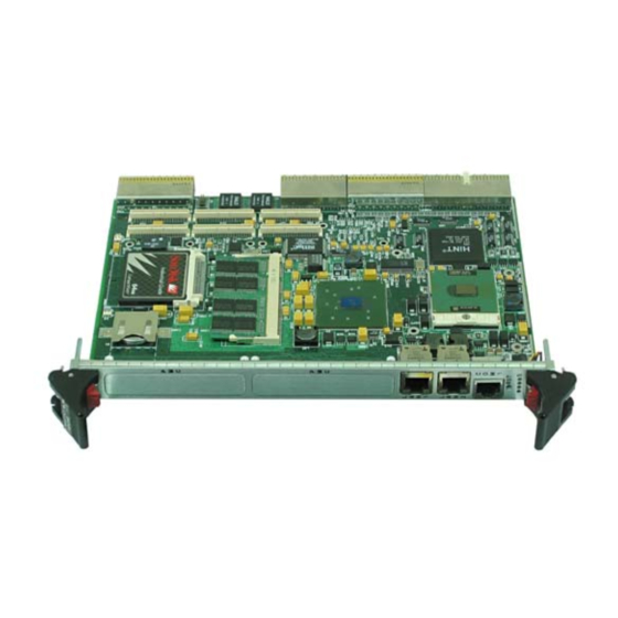
CPCI-7806*/CPCI-7806RC* Pentium/
Celeron M Universal CompactPCI Single
Board Computer
T H E C P C I - 7 8 0 6 R C I S D E S I G N E D TO M E E T T H E E U R O P E A N U N I O N ( E U )
RESTRICTIONS OF HAZARDOUS SUBSTANCE (RoHS) DIRECTIVE (2015/863)
CURRENT REVISION.
Publication No. 500-657806-000 Rev. G
Advertisement
Table of Contents

Related Manuals for abaco systems CPCI-7806


Summary of Contents for abaco systems CPCI-7806
- Page 1 Hardware Reference Manual CPCI-7806*/CPCI-7806RC* Pentium/ Celeron M Universal CompactPCI Single Board Computer T H E C P C I - 7 8 0 6 R C I S D E S I G N E D TO M E E T T H E E U R O P E A N U N I O N ( E U ) RESTRICTIONS OF HAZARDOUS SUBSTANCE (RoHS) DIRECTIVE (2015/863) CURRENT REVISION.
- Page 2 WEEE is processed in accordance with the requirements of the WEEE Directive. Abaco Systems will evaluate requests to take back products purchased by our customers before August 13, 2005 on a case-by-case basis. A WEEE management fee may apply.
- Page 3 About This Manual Conventions Notices This manual may use the following types of notice: WARNING Warnings alert you to the risk of severe personal injury. CAUTION Cautions alert you to system danger or loss of data. NOTE Notes call attention to important features or instructions. Tips give guidance on procedures that may be tackled in a number of ways.
- Page 4 This document is distributed via the Abaco website. You may register for access to manuals via the website. LINKS https://www.abaco.com/products/cpci-7806rc The following is a list of reference documentation related to CPCI-7806*/ CPCI-7806RC*: VxWorks Board Support Package Abstraction BSPX ACC-0584/ACC-0584RC Installation Guide...
- Page 5 Compliance This chapter provides the applicable information regarding regulatory compliance for the CPCI-7806/CPCI-7806RC. Abaco Systems’ CPCI-7806/CPCI-7806RC has been evaluated to and has met the requirements for compliance to the following standards: International Compliance • EN55022:1998/CISPR 22:1997 • IEC61000-4-2 • IEC61000-4-3 •...
- Page 6 Changes or modifications not expressly approved by the party responsible for compliance could void the user’s authority to operate the equipment. Canadian Regulations The CPCI-7806/CPCI-7806RC Class A digital apparatus complies with Canadian ICES-003. NOTE Any equipment tested and found compliant with FCC Part 15 for unintentional radiators or EN55022 (previously CISPR 22) satisfy ICES-003.
- Page 7 Technical Support Contact Information You can find technical assistance contact details on the website Support page. LINK https://www.abaco.com/support Abaco will log your query in the Technical Support database and allocate it a unique Case number for use in any future correspondence. Alternatively, you may also contact Abaco’s Technical Support via: LINK support@abaco.com...
-
Page 8: Table Of Contents
A.7.2 PMC #1 (J12)/PMC #2 (J22) Connector and Pinout ..........60 8 CPCI-7806/CPCI-7806RC Pentium/Celeron M Universal CompactPCI Single Board Computer... - Page 9 A.7.3 PMC #1 (J13) Connector and Pinout ............. 61 A.7.4 PMC #1 (J14) Connector and Pinout .
- Page 10 Figure 1-1 CPCI-7806/CPCI-7806RC PMC and Jumper Locations ........
- Page 11 Table 2-1 CPCI-7806/CPCI-7806RC I/O Address Map ........
- Page 12 Table E-21 NetFn 0x32, Cmd 0x80 ..............94 12 CPCI-7806/CPCI-7806RC Pentium/Celeron M Universal CompactPCI Single Board Computer...
- Page 13 • Miniature speaker • Keyboard/Mouse port (requires ACC-0584/ACC-0584RC) The 855GME chipset allows the CPCI-7806/CPCI-7806RC to provide enhanced features such as integrated video and Ultra ATA/100 IDE support. The CPCI-7806/ CPCI-7806RC are capable of executing many of today’s desktop operating ®...
- Page 14 Chapter 3 Embedded PC/RTOS Features, page 38 of this manual. The CPCI-7806/CPCI-7806RC are suitable for use in applications ranging from telecommunications, simulation, instrumentation, industrial control, process control and monitoring, factory automation, automated test systems, data acquisition systems and anywhere that the highest performance processing power in a single CompactPCI slot is desired.
-
Page 15: Figure 1 Cpci-7806/Cpci-7806Rc Block Diagram
Interface Front Front Front Front Panel Panel Panel Panel Ethernet Ethernet Ethernet Ethernet Notes: Intel 82546GB Dual Ethernet Controller is for CPCI-7806 RoHS product only. IPMI is no longer supported. Older boards may have IPMI. Publication No. 500-657806-000 Rev. G... - Page 16 Because of the danger of introducing additional hazards, do not install substitute parts or perform any unauthorized modification to the product. Return the product to Abaco Systems for service and repair to ensure that safety features are maintained. Dangerous Procedure Warnings Warnings, such as the example below, precede only potentially dangerous procedures throughout this manual.
-
Page 17: Handling And Installation
1 • Handling and Installation 1.1 Introduction This chapter describes the hardware jumper settings, connector descriptions, installation, system setup and operation of the CPCI-7806/CPCI-7806RC. 1.2 Unpacking Procedures Any precautions found in the shipping container should be observed. All items should be carefully unpacked and thoroughly inspected for damage that might have occurred during shipment. -
Page 18: Hardware Setup
1.4 Hardware Setup The CPCI-7806/CPCI-7806RC are factory populated with user-specified options as part of the CPCI-7806/CPCI-7806RC ordering information. The RAM size and CompactFlash memory size are not user-upgradable. To change RAM or CompactFlash size, contact Customer Care to receive a Return Material Authorization (RMA). -
Page 19: Figure 1-1 Cpci-7806/Cpci-7806Rc Pmc And Jumper Locations
Figure 1-1 CPCI-7806/CPCI-7806RC PMC and Jumper Locations PMC 1 PMC 2 Publication No. 500-657806-000 Rev. G Handling and Installation 19... -
Page 20: Table 1-1 Sbc Board Connectors
Normal: Boot Halt No Jumper on POST error Boot with POST Jumper error NOTE E4 jumper is factory installed 2-4 to hold jumper in place for shipping. 20 CPCI-7806/CPCI-7806RC Pentium/Celeron M Universal CompactPCI Single Board Computer Publication No. 500-657806-000 Rev. G... - Page 21 To clear the CMOS password: 1. Turn off power to the unit. 2. Place a jumper on E4 pins 1 and 2. 3. Wait approximately 5 seconds. 4. Remove jumper from E4 pins 1 and 2. 5. Power up the unit. When power is reapplied to the unit, the CMOS password will have been cleared, and the CMOS will be set to its defaults values.
-
Page 22: Installation
1.5 Installation The CPCI-7806/CPCI-7806RC conform to the CompactPCI physical specification for a 6U board. The CPCI-7806/CPCI-7806RC can be used for system control or as a peripheral board. It can be plugged directly into any standard chassis accepting either type of board. The following pictures illustrate the symbols used to identify the slots in a standard CompactPCI chassis. -
Page 23: Bios Setup
1.6 BIOS Setup The CPCI-7806/CPCI-7806RC have an onboard BIOS Setup program that controls many configuration options. These options are saved in a special non-volatile, battery-backed memory chip and are collectively referred to as the board’s ‘CMOS Configuration.’ The CMOS configuration controls many details concerning the behavior of the hardware from the moment power is applied. -
Page 24: Front/Rear Panel Connectors
1.7 Front/Rear Panel Connectors The CPCI-7806/CPCI-7806RC provides front panel access for both PMC expansion sites, two 10/100/1000 Ethernet ports, one serial port, the manual reset switch and the status LEDs. A drawing of the CPCI-7806/CPCI-7806RC front panel is shown in Figure 1-3. -
Page 25: Led Definition
1.7.1 LED Definition Figure 1-3 Front Panel LED Positions PMC 1 PMC 2 LAN Active 10BASE-T 100BASE-TX 1000BASE-T LAN Active 10BASE-T 100BASE-TX Switch 1000BASE-T LED 1 LED 2 LED 3 LED 4 CompactPCI Publication No. 500-657806-000 Rev. G Handling and Installation 25... -
Page 26: Standard Features
The following sections describe the standard features of the CPCI-7806/ CPCI-7806RC. 2.1 CPU The CPCI-7806/CPCI-7806RC CPU is factory populated with a Pentium M or Celeron M processor. The CPU speed and RAM/CompactFlash size are user specified as part of the CPCI-7806/CPCI-7806RC ordering information. -
Page 27: Physical Memory
The CPCI-7806/CPCI-7806RC provide DDR Synchronous DRAM (SDRAM) as onboard system memory. Memory can be accessed as bytes, words or longwords. The CPCI-7806/CPCI-7806RC accepts one 200-pin DDR SDRAM SODIMM along with onboard memory, for a maximum capacity of 1 Gbytes. The onboard DRAM is accessible to the CompactPCI bus through the PCI-to-PCI bridge and is addressable by the local processor. -
Page 28: I/O Port Map
2.3 I/O Port Map Like a desktop system, the CPCI-7806/CPCI-7806RC include special input/output instructions that access I/O peripherals residing in I/O addressing space (separate and distinct from memory addressing space). Locations in I/O address space are referred to as ports. When the CPU decodes and executes an I/O instruction, it produces a 16-bit I/O address on lines A00 to A15 and identifies the I/O cycle with the M/I/O control line. - Page 29 2048 Reserved *While these I/O ports are reserved for the listed functions, they are not implemented on the CPCI-7806/ CPCI-7806RC. They are listed here to make the user aware of the standard PC usage of these ports. Publication No. 500-657806-000 Rev. G...
-
Page 30: Interrupts
Determined by BIOS Not Assigned Determined by BIOS Mouse Math Coprocessor AT Hard Drive CompactFlash Drive NOTE IPMI is no longer supported. Older boards may have IPMI. 30 CPCI-7806/CPCI-7806RC Pentium/Celeron M Universal CompactPCI Single Board Computer Publication No. 500-657806-000 Rev. G... -
Page 31: Table 2-3 Pc Interrupt Vector Table
Table 2-3 PC Interrupt Vector Table INTERRUPT NO. REAL MODE PROTECTED MODE LINE Divide Error Same as Real Mode Debug Single Step Same as Real Mode Memory Parity Error, Same as Real Mode CompactPCI Interrupts (Must be enabled in BIOS Setup) Debug Breakpoint Same as Real Mode... -
Page 32: Pci Interrupts
(up to a maximum of four functions), or any combination thereof. A single function can never generate an interrupt request on more than one INTx# line. 32 CPCI-7806/CPCI-7806RC Pentium/Celeron M Universal CompactPCI Single Board Computer Publication No. 500-657806-000 Rev. G... -
Page 33: Pci Device Interrupt Map
INTH *Device 20 = INTs E, F, G, H Device 21 = INT E **Intel 82546EB is used on non-RoHS version of product (CPCI-7806) ***Intel 82546GB is used on RoHS version of product (CPCI-7806RC) Publication No. 500-657806-000 Rev. G Standard Features 33... -
Page 34: Figure 2-1 Connections For The Pc Interrupt Logic Controller
1. The NMI Enable and Real-Time Clock register can mask the NMI signal and disable/enable all NMI sources. 34 CPCI-7806/CPCI-7806RC Pentium/Celeron M Universal CompactPCI Single Board Computer Publication No. 500-657806-000 Rev. G... -
Page 35: Integrated Peripherals
NMI Enable - 1 = Disable, 0 = Enable 2.6 Integrated Peripherals The CPCI-7806/CPCI-7806RC incorporate an SMSC Super I/O (SIO) chip. The SIO provides the CPCI-7806/CPCI-7806RC with a standard floppy drive controller, two 16550 UART-compatible serial ports, keyboard and mouse ports, and general purpose I/O for system functions. -
Page 36: Ethernet Controller
2.7 Ethernet Controller The network capability is provided by the Intel 82546EB Ethernet Controller for the non-RoHS version of the product (CPCI-7806) and the Intel 82546GB Ethernet Controller for the RoHS version of the product (CPCI-7806RC). This Ethernet controller is PCI bus based and is software configurable. The CPCI-7806/ CPCI-7806RC support 10BASE-T, 100BASE-TX and 1000BASE-T Dual Channel Ethernet. -
Page 37: Video Graphics Adapter
2.8 Video Graphics Adapter The SVGA port on the CPCI-7806/CPCI-7806RC is controlled by the Intel Graphic and Memory Controller Hub (GMCH) chip. The GMCH is hardware and BIOS compatible with the industry EGA and SVGA standards supporting both VESA high-resolution and extended video modes. -
Page 38: Embedded Pc/Rtos Features
Bridge device that performs universal PCI bridging functions for embedded and intelligent I/O applications. The PCI device acts as a gateway to an intelligent subsystem. As a peripheral controller it allows the local CPCI-7806/CPCI-7806RC processor to configure and control the onboard local subsystem independent from the CompactPCI bus host processor. -
Page 39: Transaction Forwarding
3.1.4 Transaction Forwarding • Three primary interface base address configuration registers for downstream forwarding with size and prefetchable programming for all three address ranges • Direct offset address translation for downstream memory and I/O transactions • Three secondary interface address ranges for upstream forwarding, with size and prefetchable programming for all three address ranges NOTE Configuration of the Universal Bridge memory and IO register space is selected via the CMOS Setup... -
Page 40: Figure 3-1 Watchdog Timer Block Diagram
35-bit down counter until the next time the WDT enters the second stage. Figure 3-1 Watchdog Timer Block Diagram Configuration Registers Preload Value 2 Preload Value 1 Down-Counter Reset/Interrupt Control Logic WDT_TOUT# SMI/SCI/IRQ (External) (Internal) 40 CPCI-7806/CPCI-7806RC Pentium/Celeron M Universal CompactPCI Single Board Computer Publication No. 500-657806-000 Rev. G... -
Page 41: Registers
3.2.3 Registers Table 3-1 Configuration Registers Offset Register Default Type 00-01h Vendor ID 8086h Read Only 02-03h Device ID 25ABh Read Only 04-05h Command Register (COM) 0000h Read/Write 06-07h Device Status Register (DS) 0280h Read/Write Clear Revision ID Register (RID) Read Only Programming Interface register (PI) Read Only... -
Page 42: Table 3-5 Command Register (Com)
Fast Back-to-Back Capable: Reserved as ‘1’. Read Only UDF - User Definable Features: Reserved as ‘0’. Read Only 66 MHz Capable: Reserved as ‘0’. Read Only Reserved. Read Only 42 CPCI-7806/CPCI-7806RC Pentium/Celeron M Universal CompactPCI Single Board Computer Publication No. 500-657806-000 Rev. G... -
Page 43: Table 3-9 Revision Identification Register (Rid)
Table 3-9 Revision Identification Register (RID) Offset Attribute Read Only Default Value Size 8 bit Lockable Power Well Core Table 3-10 Programming Interface Register (PI) Offset Attribute Read Only Default Value Size 8 bit Lockable Power Well Core Table 3-11 Sub Class Code Register (SCC) Offset Attribute Read Only... -
Page 44: Table 3-16 Subsystem Vendor Id (Svid)
1 - The 20-bit Preload Value is loaded into bits 24:5 of the main down counter. The resulting timer clock is the PCI Clock (33 MHz) divided by 2 . The approximate clock generated is 1 MHz, (1μ to 1 sec). 44 CPCI-7806/CPCI-7806RC Pentium/Celeron M Universal CompactPCI Single Board Computer Publication No. 500-657806-000 Rev. G... -
Page 45: Table 3-20 Wdt Lock Register
Table 3-19 Details of WDT Configuration Register (Continued) Attribute Description WDT_INT_TYPE: The WDT timer supports programmable routing of interrupts. The set of bits allows the user to choose the type of interrupt desired when the WDT reached the end of the first stage without being reset. 00 = IRQ* (APIC 1, INT 10**) (Default) 01 = Reserved 10 = SMI... -
Page 46: Table 3-22 Manufacturer's Id
Table 3-26 Preload Value 2 Register Offset Base + 04h Attribute Read-Write Default Value FFFFFh Size 32 bit Lockable Power Well Core 46 CPCI-7806/CPCI-7806RC Pentium/Celeron M Universal CompactPCI Single Board Computer Publication No. 500-657806-000 Rev. G... -
Page 47: Table 3-27 Details Of Preload Value 2 Register
Table 3-27 Details of Preload Value 2 Register Attribute Description 31:20 Reserved 19:0 Preload_Value_2 [19:0]: Use this register to hold the preload value for the WDT Timer. The value in the Preload register is automatically transferred into the 35-bit down counter every time the WDT enters the first stage. -
Page 48: Register Unlocking Sequence
1 Gbyte. This CompactFlash appears to the user as an intelligent ATA (IDE) disk drive with the same functionality and capabilities as a “rotating media” IDE hard drive. The CPCI-7806/CPCI-7806RC BIOS includes an option to allow the board to boot from the CompactFlash. -
Page 49: Functionality
Some applications may require the use of multiple partitions. The following discussion of these partitions includes special procedures that must be followed to create multiple partitions on the CPCI-7806/ CPCI-7806RC IDE disk devices (including the resident CompactFlash). - Page 50 FDISK. This has been shown to be an important step in a successful partitioning effort. 1. Power up the CPCI-7806/CPCI-7806RC and enter the CMOS set-up. 2. Set IDE HDD Master to “Not Installed.” 3. Set CompactFlash Master to “AUTO.”...
-
Page 51: Remote Ethernet Booting
3.4 Remote Ethernet Booting The CPCI-7806/CPCI-7806RC is capable of booting from a server over a network utilizing the Argon LAN BIOS. The BIOS gives you the ability to remotely boot the CPCI-7806/CPCI-7806RC using a variety of network protocols. The Ethernet must be connected through the LAN front panel (RJ45) or CompactPCI back panel connector to boot remotely. -
Page 52: Ipmi 1.5
IPMI Firmware and OEM Extensions for details of the IPMI capabilities of the onboard peripheral management controller. NOTE IPMI is no longer supported. Older boards may have IPMI. 52 CPCI-7806/CPCI-7806RC Pentium/Celeron M Universal CompactPCI Single Board Computer Publication No. 500-657806-000 Rev. G... -
Page 53: J1 Connector Pinout
A • Connectors and Pinouts The CPCI-7806/CPCI-7806RC CompactPCI Universal SBC has several connectors for its I/O ports. Wherever possible, the CPCI-7806/CPCI-7806RC uses connectors and pinouts typical for any desktop PC. This ensures maximum compatibility with a variety of systems. Connector diagrams in this appendix are generally shown in a natural orientation with the controller board mounted in a CompactPCI bus chassis. -
Page 54: J2 Connector Pinout
A.2 J2 Connector Pinout The CPCI-7806/CPCI-7806RC J2 connector is a 2 mm “Hard Metric” CompactPCI connector, with 5 rows of 22 pins each. J2 is required for system slot SBCs. An additional external metal shield, labeled row F, is also used. This connector’s controlled impedance minimizes unwanted signal reflections. -
Page 55: J3 Connector Pinout
A.3 J3 Connector Pinout The J3 connector is a 5 row, 19 pins each, 2 mm “Hard Metric” CompactPCI connector. An additional external metal shield is also used, labeled row F. Figure A-3 illustrates the J3 connector and the connector pinout. This connector is used to route the I/O signals of the PMC Site #2 and the serial and floppy drive signals to the backplane I/O. -
Page 56: J5 Connector Pinout
A.4 J5 Connector Pinout The CPCI-7806/CPCI-7806RC J5 connector is a 2 mm “Hard Metric” CompactPCI connector, with 5 rows of 22 pins each. An additional external metal shield is also used, labeled row F. This connector is used to route the I/O signals of PMC Site #1, and the IDE, serial and USB signals to the backplane I/O. -
Page 57: Ethernet Connector Pinout
A.5 Ethernet Connector Pinout The pinout diagram for the Ethernet 10BASE-T, 100BASE-TX and 1000BASE-T connector (J6, J7) is shown in Figure A-5. Figure A-5 Ethernet Connector and Pinout ETHERNET CONNECTOR (10BASE-T, 100BASE-TX, 1000BASE-T) Signal Name Description BI_DA+ Bi-directional pair A + BI_DA- Bi-directional pair A - BI_DB+... -
Page 58: Serial Connector Pinout (Com1) J8
Figure A-6 Serial Connector and Pinout COM 1 SERIAL PORT CONNECTOR J8 Assignment NOTE An RJ45 to DB9 adapter cable (360-010030-001) is shipped with the CPCI-7806/CPCI-7806RC. Table A-1 RJ45 - DB9 Adapter Pinout Assignment 58 CPCI-7806/CPCI-7806RC Pentium/Celeron M Universal CompactPCI Single Board Computer... -
Page 59: Pmc Connector Pinout
A.7 PMC Connector Pinout A.7.1 PMC #1 (J11)/PMC #2 (J21) Connector and Pinout The PCI Mezzanine Card (PMC) carries the same signals as the PCI standard; however, the PMC standard uses a completely different form factor. Table A-2 through are the pinouts for the PMC connectors. Table A-2 PMC #1 (J11)/PMC #2 (J21) Connector Pinout PMC Connector (J11/J21) PMC Connector (J11/J21) -
Page 60: Pmc #1 (J12)/Pmc #2 (J22) Connector And Pinout
AD[18] ACK64# +3.3 V AD[16] C/BE#[2] Signal names are generic labels. J12 signals are for the PCI1 bus and J22 signals are for the PCI0 bus. 60 CPCI-7806/CPCI-7806RC Pentium/Celeron M Universal CompactPCI Single Board Computer Publication No. 500-657806-000 Rev. G... -
Page 61: Pmc #1 (J13) Connector And Pinout
A.7.3 PMC #1 (J13) Connector and Pinout Table A-4 PMC #1 J13 Connector Pinout PMC Connector (J13) PMC Connector (J13) Left Side Right Side Left Side Right Side Pin Name Name Pin Name Name PCI1_AD[48] PCI1_C/BE#[7] PCI1_AD[47] PCI1_AD[46] PCI1_C/BE#[6] PCI1_C/BE#[5] PCI1_AD[45] PCI1_C/BE#[4] VCC_3.3... -
Page 62: Pmc #1 (J14) Connector And Pinout
J14-30 J5 pin A17 61 J14-61 J5 pin E10 J14-62 J5 pin D10 J14-31 J5 pin E16 J14-32 J5 pin D16 63 J14-63 J5 pin C10 J14-64 J5 pin B10 62 CPCI-7806/CPCI-7806RC Pentium/Celeron M Universal CompactPCI Single Board Computer Publication No. 500-657806-000 Rev. G... -
Page 63: First Boot
B.1 First Boot The CPCI-7806/CPCI-7806RC have a First Boot menu enabling the user to, on a one time basis, select a drive device to boot from. This feature is useful when installing from a bootable disk. For example, when installing Windows NT from a CD, enter the First Boot menu and use the arrows keys to highlight ATAPI CD-ROM Drive. -
Page 64: Main
Select Item System Time [11:39:40] Change Field System Date [Tue 03/04/2004] Select Field General Help Save and Exit Exit 002.53 (C) Copyright 1985-2002, American Megatrends, Inc. 64 CPCI-7806/CPCI-7806RC Pentium/Celeron M Universal CompactPCI Single Board Computer Publication No. 500-657806-000 Rev. G... -
Page 65: Advanced Bios Setup
B.3 Advanced BIOS Setup The Advanced BIOS Setup menu allows the user to configure some CPU settings, the IDE bus, other external devices and internal drives. Select the Advanced tab from the setup screen to enter the Advanced BIOS Setup screen. -
Page 66: Pci/Pnp Setup
Select Item IRQ7 [Available] Change Option IRQ9 [Available] General Help IRQ10 [Available] Save and Exit IRQ11 [Available] Exit IRQ14 [Available] 002.53 (C) Copyright 1985-2002, American Megatrends, Inc. 66 CPCI-7806/CPCI-7806RC Pentium/Celeron M Universal CompactPCI Single Board Computer Publication No. 500-657806-000 Rev. G... -
Page 67: Boot Setup
B.5 Boot Setup Use the Boot Setup menu to set the priority of the boot devices, including booting from a remote network. The devices shown in this menu are the bootable devices detected during POST. If a drive is installed that does not appear, verify the hardware installation. -
Page 68: Security Setup
• Momentarily short pins 2-3 of E4 for approximately five seconds. • Power up the unit. When power is reapplied to the unit, the CMOS password will be cleared. 68 CPCI-7806/CPCI-7806RC Pentium/Celeron M Universal CompactPCI Single Board Computer Publication No. 500-657806-000 Rev. G... -
Page 69: Chipset Setup
B.7 Chipset Setup Select the various options for chipsets located in the system (for example, the CPU configuration and configurations for the North and South Bridge). The settings for the chipsets are processor dependent and care must be used when changing settings from the defaults set at the factory. -
Page 70: Exit Menu
If changes have previously been made in the BIOS and the system malfunctions, reboot the system and access this screen. Select ‘Load Failsafe Defaults’ and continue the reboot. 70 CPCI-7806/CPCI-7806RC Pentium/Celeron M Universal CompactPCI Single Board Computer Publication No. 500-657806-000 Rev. G... -
Page 71: Boot-From-Lan Bios Option
First Boot menu. Selecting Network: IBA LAN to boot from the LAN in this screen applies to the current boot only. At the next reboot the CPCI-7806/CPCI-7806RC will revert back to the setting in the Boot menu. -
Page 72: Boot Menu
Once you press CTRL-S, the Boot Agent setup menu will appear. PXE is the boot option available on the CPCI-7806/CPCI-7806RC. You can change the settings for the Setup Prompt and Setup Menu Wait Time. You can either enable or disable the prompt, and you can set the amount of wait time for the setup menu. -
Page 73: Managed Pc Boot Agent Option
First Boot menu. Selecting Managed PC Boot Agent (MBA) to boot from the LAN in this screen applies to the current boot only. At the next reboot the CPCI-7806/ CPCI-7806RC will revert back to the setting in the Boot menu. -
Page 74: Boot Menu
Boot Failure: Next boot device Use cursor keys to edit: Up/Down change field, Left/Right change value ESC to quit, F9 restore previous settings, F10 to save 74 CPCI-7806/CPCI-7806RC Pentium/Celeron M Universal CompactPCI Single Board Computer Publication No. 500-657806-000 Rev. G... -
Page 75: Table C-4 Tcp/Ip Default Settings
TCP/IP Menu Table C-4 TCP/IP Default Settings Argon Managed PC Boot Agent (MBA) v4.00 (BIOS Integrated) (c) Copyright 2002 Argon Technology Corporation All rights reserved Configuration Boot Method: TCP/IP Protocol DHCP Config Message: Enabled Message Timeout: 3 Seconds Boot failure Prompt: Wait for timeout Boot Failure: Next boot device... -
Page 76: Table C-6 Pxe Default Settings
Boot Failure: Next boot device Use cursor keys to edit: Up/Down change field, Left/Right change value ESC to quit, F9 restore previous settings, F10 to save 76 CPCI-7806/CPCI-7806RC Pentium/Celeron M Universal CompactPCI Single Board Computer Publication No. 500-657806-000 Rev. G... -
Page 77: Microsoft Windows 2000 Professional Software Driver Installation
Intel 855GME chipset. High performance LAN operation is provided by a dual-port Intel FW82546EB Gigabit Ethernet adapter on the non-RoHS version of the product (CPCI-7806) and a dual-port Intel FW82546GB Gigabit Ethernet adapter on the RoHS version of the product (CPCI-7806RC). -
Page 78: Usb 2.0 Ehci Host Controller
‘Network adapters’ section in the right pane. 4. Click ‘X’ to close the ‘Computer Management’ window. 5. Changes may be made to the network configuration as desired. 78 CPCI-7806/CPCI-7806RC Pentium/Celeron M Universal CompactPCI Single Board Computer Publication No. 500-657806-000 Rev. G... -
Page 79: Microsoft Windows Xp Professional Software Driver Installation
D.2 Microsoft Windows XP Professional Software Driver Installation NOTE Prior to installing device drivers, Windows XP should be updated to Service Pack 1a or later. Visit http://support.microsoft.com and search for the latest Service Pack information. D.2.1 Video Driver Installation 1. If not already present, insert the Windows Drivers CD-ROM. 2. -
Page 80: Ethernet Adapter Drivers Installation
‘Finish.’ Device Manager will relocate the devices to the ‘Network adapters’ section in the right pane. 4. Click ‘X’ to close the ‘Computer Management’ window. 5. Changes may be made to the network configuration as desired. 80 CPCI-7806/CPCI-7806RC Pentium/Celeron M Universal CompactPCI Single Board Computer Publication No. 500-657806-000 Rev. G... -
Page 81: Standard Ipmi Commands
E • IPMI Firmware and OEM Extensions The IPMI firmware provides all the mandatory standard commands specified in the IPMI 1.5 framework. The firmware also provides functionality beyond that of a normal Peripheral Manager, by implementing several commands in the OEM range (per IPMI spec). -
Page 82: Cold Reset
[3] 1b = SDR repository empty [2] 1b = Internal use area of FRU corrupted [1] 1b = controller update ‘boot block’ firmware corrupted [0] 1b = controller operational firmware corrupted 82 CPCI-7806/CPCI-7806RC Pentium/Celeron M Universal CompactPCI Single Board Computer Publication No. 500-657806-000 Rev. G... -
Page 83: Setacpi Power State
E.3.2 SetACPI Power State This command is used to set the platform management subsystem to a particular power state. The firmware does not support the ACPI power state, instead it can be used to turn off/on power to the board. Table E-5 NetFn 0x06, Cmd 0x06 Byte Value... -
Page 84: Broadcast Get Device Id
C2 Local 1 Slave Address [0] - reserved Read count – number of bytes to read 1 based, 0 = no bytes to read. Data to write 84 CPCI-7806/CPCI-7806RC Pentium/Celeron M Universal CompactPCI Single Board Computer Publication No. 500-657806-000 Rev. G... -
Page 85: Set Event Receiver
Table E-8 NetFn 0x06, Cmd 0x52 (Continued) Response-data Completion code 00h – if successful 81h – Lost Arbitration 82h – Bus Error 83h – NAK on Write 84h – Truncated Read Bytes read from the specified slave address. E.3.7 Set Event Receiver This command sets the slave address and the LUN of the Event Receiver, which will receive the Event Messages generated by the IPMI subsystem. -
Page 86: Table E-11 Netfn 0X04, Cmd 0X2D
= actual voltage = “raw” sensor reading e.g.: if sensor 0x41 says 0xC0 (192 decimal), the actual voltage is (192/256) * 3.3/2.5 * 3.3 = 3.267 V. 86 CPCI-7806/CPCI-7806RC Pentium/Celeron M Universal CompactPCI Single Board Computer Publication No. 500-657806-000 Rev. G... -
Page 87: Fru Inventory Area Info
b. For 5 V sensors = (V / 256) * 3.3 * 2 Where V = actual voltage = “raw” sensor reading e.g.: if sensor 0x44 says 0xC3 (195 decimal), the actual voltage is (195/256) * 3.3 * 2 = 5.027 V. c. -
Page 88: Write Fru Data
FRU Inventory offset to write. MS Byte. 4:3+N Data to write Response-data Completion code 00h – successful 80h – Write protected Count written – 1 based 88 CPCI-7806/CPCI-7806RC Pentium/Celeron M Universal CompactPCI Single Board Computer Publication No. 500-657806-000 Rev. G... -
Page 89: Get Sdr Repository Info
E.3.13 Get SDR Repository Info This command returns the SDR command version for the SDR Repository. Table E-15 NetFn 0x0A, Cmd 0x20 Byte Value Data Field Comments Request-data Response-data Completion code SDR Version. Record count LS Byte. Record count MS Byte. XXXXh Free space in bytes. -
Page 90: Fru Data Specification
CA 45 54 F3 90 B6 80 49-94 B0 0B F8 C2 78 47 FD .ET..I..xG. 00F0 C0 33 00 06 78 00 00 00-00 00 00 00 00 00 00 00 .3..x... 90 CPCI-7806/CPCI-7806RC Pentium/Celeron M Universal CompactPCI Single Board Computer Publication No. 500-657806-000 Rev. G... -
Page 91: Platform Events
E.5 Platform Events The Abaco IPMI subsystem contains several sensors for reading the voltages and temperature of the system. Each sensor is configured with a threshold, hysteresis, and nominal value. When the value of a sensor crosses a threshold, a platform event is sent to the “Event Receiver”. -
Page 92: Chassis Control
The Abaco IPMI firmware can perform some of the functions of a Baseboard Management Controller. The firmware can send IPMI commands to other targets on the IPMB on behalf of the CPCI-7806/CPCI-7806RC, and return the responses to the CPCI-7806/CPCI-7806RC. It can also forward any platform events it receives to the CPCI-7806/CPCI-7806RC. -
Page 93: Table E-20 Netfn 0X32, Cmd 0X00
As an example, consider a system with a CPCI-7806/CPCI-7806RC at address 0xB0, and a CPCI-7806/CPCI-7806RC at address 0xBA. For the first card to send a “Get Sensor Reading” to the second card, it must have the Zircon send the request and relay the response back to the sender. -
Page 94: Forwarding Of Platform Events
“Set Platform Event Forwarding Address” command. The CPCI-7806/CPCI-7806RC should not send a response for the Platform Event to the Zircon nor to the originating device, as the Zircon has already responded. - Page 95 © 2018 Abaco Systems, Inc. All rights reserved. Information Centers For more information, please visit the * indicates a trademark of Abaco Systems, Inc. and/or its affiliates. All other Abaco Systems website at: Americas: trademarks are the property of their 1-866-652-2226 (866-OK-ABACO) respective owners.
Need help?
Do you have a question about the CPCI-7806 and is the answer not in the manual?
Questions and answers