Sign In
Upload
Manuals
Brands
abaco systems Manuals
Motherboard
CPCI-7806
abaco systems CPCI-7806 Manuals
Manuals and User Guides for abaco systems CPCI-7806. We have
1
abaco systems CPCI-7806 manual available for free PDF download: Hardware Reference Manual
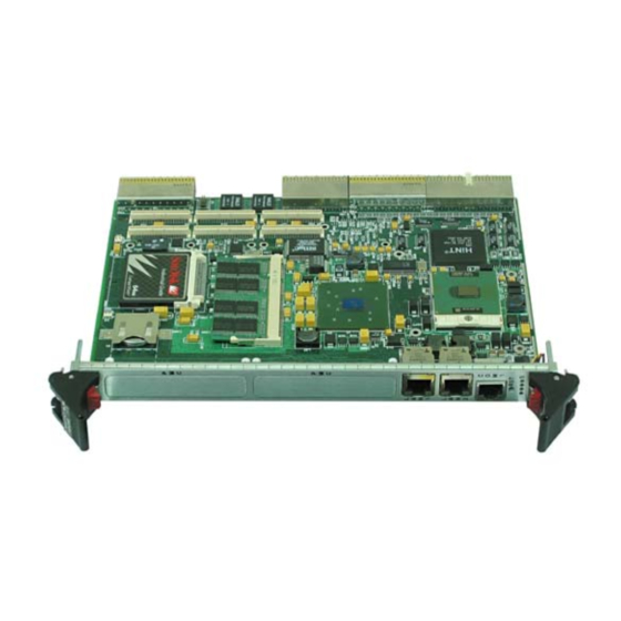
abaco systems CPCI-7806 Hardware Reference Manual (95 pages)
Pentium/Celeron M Universal CompactPCI Single Board Computer
Brand:
abaco systems
| Category:
Motherboard
| Size: 0.83 MB
Table of Contents
Table of Contents
8
Figure 1 CPCI-7806/CPCI-7806RC Block Diagram
15
1 Handling and Installation
17
Introduction
17
Unpacking Procedures
17
Handling Precaution
17
Hardware Setup
18
Figure 1-1 CPCI-7806/CPCI-7806RC PMC and Jumper Locations
19
Table 1-1 SBC Board Connectors
20
Table 1-2 Battery Enable (User Configurable) - Jumper (E3)
20
Table 1-3 Password Clear and Boot Continuation (User Configurable) - Jumper (E4)
20
Installation
22
BIOS Setup
23
Figure 1-2 Installing a PMC Card on the CPCI-7806/CPCI-7806RC
23
Front/Rear Panel Connectors
24
LED Definition
25
Figure 1-3 Front Panel LED Positions
25
2 Standard Features
26
Cpu
26
Physical Memory
27
I/O Port Map
28
Table 2-1 CPCI-7806/CPCI-7806RC I/O Address Map
28
Interrupts
30
System Interrupts
30
Table 2-2 PC Hardware Interrupt Line Assignments
30
Table 2-3 PC Interrupt Vector Table
31
PCI Interrupts
32
PCI Device Interrupt Map
33
Table 2-4 PCI Device Interrupt Mapping by the BIOS
33
Figure 2-1 Connections for the PC Interrupt Logic Controller
34
Integrated Peripherals
35
Table 2-5 NMI Register Bit Descriptions
35
Ethernet Controller
36
Video Graphics Adapter
37
Table 2-6 Supported Graphics Video Resolutions for Windows 2000
37
Table 2-7 Supported Graphics Video Resolutions for Windows XP
37
3 Embedded PC/RTOS Features
38
Compactpci Bus Bridge
38
PCI Interface
38
Buffer Architecture
38
Configuration Register and Control/Status Registers (Csrs)
38
Transaction Forwarding
39
Watchdog Timer
39
General
39
Function
39
Figure 3-1 Watchdog Timer Block Diagram
40
Registers
41
Table 3-1 Configuration Registers
41
Table 3-2 Memory Mapped Registers
41
Table 3-3 Vendor Identification Register (VID)
41
Table 3-4 Device Identification Register (DID)
41
Table 3-5 Command Register (COM)
42
Table 3-6 Details of Command Register (COM)
42
Table 3-7 Device Status Register (DS)
42
Table 3-8 Details of Device Status Register (DS)
42
Table 3-9 Revision Identification Register (RID)
43
Table 3-10 Programming Interface Register (PI)
43
Table 3-11 Sub Class Code Register (SCC)
43
Table 3-12 Base Code Class Register (BCC)
43
Table 3-13 Header Type Register (HEDT)
43
Table 3-14 Base Address Register 1 (BAR1)
43
Table 3-15 Details of Base Address Register 1 (BAR1)
43
Table 3-16 Subsystem Vendor ID (SVID)
44
Table 3-17 Subsystem ID (SID)
44
Table 3-18 WDT Configuration Register
44
Table 3-19 Details of WDT Configuration Register
44
Table 3-20 WDT Lock Register
45
Table 3-21 Details of WDT Lock Register
45
Table 3-22 Manufacturer's ID
46
Table 3-23 Details of Manufacturer's ID
46
Table 3-24 Preload Value 1 Register
46
Table 3-25 Details of Preload Value 1 Register
46
Table 3-26 Preload Value 2 Register
46
Table 3-27 Details of Preload Value 2 Register
47
Table 3-28 General Interrupt Status Register
47
Table 3-29 Details of General Interrupt Status Register
47
Table 3-30 Reload Register
47
Table 3-31 Details of Reload Register
47
Register Unlocking Sequence
48
Reload Sequence
48
Compactflash
48
Configuration
48
Functionality
49
Figure 3-2 Typical System Configuration
49
Remote Ethernet Booting
51
PICMG 2.16 Ethernet
51
Ipmi 1.5
52
J1 Connector Pinout
53
Figure A-1 J1 Connector and Pinout
53
J2 Connector Pinout
54
Figure A-2 J2 Connector and Pinout
54
J3 Connector Pinout
55
Figure A-3 J3 Connector and Pinout
55
J5 Connector Pinout
56
Figure A-4 J5 Connector and Pinout
56
Ethernet Connector Pinout
57
Figure A-5 Ethernet Connector and Pinout
57
Serial Connector Pinout (COM1) J8
58
Figure A-6 Serial Connector and Pinout
58
Table A-1 RJ45 - DB9 Adapter Pinout
58
PMC Connector Pinout
59
PMC #1 (J11)/PMC #2 (J21) Connector and Pinout
59
Table A-2 PMC #1 (J11)/PMC #2 (J21) Connector Pinout
59
PMC #1 (J12)/PMC #2 (J22) Connector and Pinout
60
Table A-3 PMC #1 (J12)/PMC #2 (J22) Connector Pinout
60
PMC #1 (J13) Connector and Pinout
61
Table A-4 PMC #1 J13 Connector Pinout
61
PMC #1 (J14) Connector and Pinout
62
Table A-5 PMC #1 J14 Connector Pinout
62
First Boot
63
Main
64
Advanced BIOS Setup
65
Pci/Pnp Setup
66
Boot Setup
67
Security Setup
68
Chipset Setup
69
Exit Menu
70
Boot-From-LAN BIOS Option
71
First Boot Menu
71
Table C-1 First Boot Menu
71
Boot Menu
72
BIOS Features Setup
72
Table C-2 Boot-From-LAN BIOS Boot Menu
72
Managed PC Boot Agent Option
73
First Boot Menu
73
Table C-1 Intel Boot Agent First Boot Menu
73
Boot Menu
74
BIOS Features Setup
74
Table C-2 Managed PC Boot Agent Boot Menu
74
Table C-3 RPL Default Settings
74
Table C-4 TCP/IP Default Settings
75
Table C-5 Netware Default Settings
75
Table C-6 PXE Default Settings
76
Microsoft Windows 2000 Professional Software Driver Installation
77
Video Driver Installation
77
Hance Rapids Chipset Software Installation
77
USB 2.0 EHCI Host Controller
78
Ethernet Adapter Drivers Installation
78
Microsoft Windows XP Professional Software Driver Installation
79
Video Driver Installation
79
Hance Rapids Chipset Software Installation
79
USB 2.0 EHCI Host Controller
79
Ethernet Adapter Drivers Installation
80
Standard IPMI Commands
81
Get Device ID
81
Table E-1 Netfn 0X06, CMD 0X01
81
Cold Reset
82
Warm Reset
82
Get Self-Test Results
82
Table E-2 Netfn 0X06, CMD 0X02
82
Table E-3 Netfn 0X06, CMD 0X03
82
Table E-4 Netfn 0X06, CMD 0X04
82
Setacpi Power State
83
Get ACPI Power State
83
Get Device GUID Command
83
Table E-5 Netfn 0X06, CMD 0X06
83
Table E-6 Netfn 0X06, CMD 0X07
83
Broadcast Get Device ID
84
Master-Write-Read
84
Table E-7 Netfn 0X06, CMD 0X08
84
Table E-8 Netfn 0X06, CMD 0X52
84
Set Event Receiver
85
Get Event Receiver
85
Get Sensor Reading
85
Table E-9 Netfn 0X04, CMD 0X00
85
Table E-10 Netfn 0X04, CMD 0X01
85
Table E-11 Netfn 0X04, CMD 0X2D
86
FRU Inventory Area Info
87
Read FRU Data
87
Table E-12 Netfn 0X0A, CMD 0X10
87
Write FRU Data
88
Table E-13 Netfn 0X0A, CMD 0X11
88
Table E-14 Netfn 0X0A, CMD 0X12
88
Get SDR Repository Info
89
Reserve SDR Repository Command
89
Get SDR Command
89
Table E-15 Netfn 0X0A, CMD 0X20
89
Table E-16 Netfn 0X0A, CMD 0X22
89
FRU Data Specification
90
Table E-17 Netfn 0X0A, CMD 0X23
90
Platform Events
91
Table E-18 Netfn 0X04, CMD 0X02
91
Chassis Control
92
Get Geographical Address
92
BMC Functions
92
IPMB Relay
92
Table E-19 Netfn 0X30, CMD 0X01
92
Table E-20 Netfn 0X32, CMD 0X00
93
Forwarding of Platform Events
94
Set Platform Event Forwarding Address
94
Table E-21 Netfn 0X32, CMD 0X80
94
Advertisement
Advertisement
Related Products
abaco systems CPCI-7806RC
Abaco Systems CR9 Series
Abaco Systems CT9 Series
abaco systems CP11 Series
abaco systems CR11 Series
abaco systems CEI-420
abaco systems CEI-420A
abaco systems CEI-520
abaco systems CEI-200 Series
abaco systems CEI520A
abaco systems Categories
Motherboard
Single board computers
Computer Hardware
Switch
Recording Equipment
More abaco systems Manuals
Login
Sign In
OR
Sign in with Facebook
Sign in with Google
Upload manual
Upload from disk
Upload from URL