Table of Contents
Advertisement
Quick Links
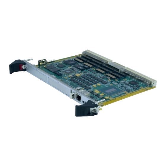
Hardware Reference Manual
®
XVR16* 4th Generation Intel
Core™ i7
B a s e d R u g g e d V M E S i n g l e B o a r d
Computer
THE XVR16 IS DESIGNED TO MEET THE EUROPEAN UNION (EU) RESTRICTIONS OF
HAZARDOUS SUBSTANCE (ROHS) DIRECTIVE (2002/95/EC) CURRENT REVISION.
Publication No. 500-9300007876-000 Rev. C.0
Advertisement
Table of Contents

Related Manuals for abaco systems XVR16 Series


Summary of Contents for abaco systems XVR16 Series
- Page 1 Hardware Reference Manual ® XVR16* 4th Generation Intel Core™ i7 B a s e d R u g g e d V M E S i n g l e B o a r d Computer THE XVR16 IS DESIGNED TO MEET THE EUROPEAN UNION (EU) RESTRICTIONS OF HAZARDOUS SUBSTANCE (ROHS) DIRECTIVE (2002/95/EC) CURRENT REVISION.
-
Page 2: Document History
WEEE is processed in accordance with the requirements of the WEEE Directive. Abaco Systems will evaluate requests to take back products purchased by our customers before August 13, 2005 on a case-by-case basis. A WEEE management fee may apply. -
Page 3: About This Manual
About This Manual Conventions Notices This manual may use the following types of notice: WARNING Warnings alert you to the risk of severe personal injury. CAUTION Cautions alert you to system danger or loss of data. NOTE Notes call attention to important features or instructions. Tips give guidance on procedures that may be tackled in a number of ways. -
Page 4: Further Information
Further Information Abaco Website You can find information regarding Abaco products on the following website: LINK https://www.abaco.com Abaco Documents This document is distributed via the Abaco website. You may register for access to manuals via the website. LINK https://www.abaco.com/products/ Third-party Documents ANSI/VITA 1.1-1994 American National Standard for VME64 (R2002) -
Page 5: June
ANSI/VITA 42.0 American National Standard for XMC December 2008 ANSI/VITA 42.3 American National Standard for XMC PCI Express Protocol Layer Standard June 2006 ANSI/VITA 61.0 XMC 2.0 November 2011 European Union Directive 2002/95/EC of the European Parliament of 27 January 2003 on the Restriction of the Use of Certain Hazardous Substances in Electrical and Electronic Equipment (RoHS) European Union, Directive 2002/96/EC of the European Parliament of ... - Page 6 PICMG 2.9 System Management Specification, Rev 1.0, May 2002 PCI Special Interest Group (SIG), PCI Local Bus Specification, Revision 2.2 December 1998 PCI Special Interest Group (SIG), PCI Express Base Specification, Revision 1.1 March 2005 S-ATA, Serial ATA: High Speed Serialized AT Attachment, Revision 1.0A January 2003 Universal Serial Bus 3.0 Specification, Revision 1.0 November 2008...
- Page 7 The following documents are continuously updated and are available at: LINK www.intel.com/products/processor/manuals/ Intel 64 and IA-32 Architectures Software Developerʹs Manual Volume 1: Basic Architecture Intel 64 and IA-32 Architectures Software Developerʹs Manual Volume 2A: Instruction Set Reference, A-M ...
- Page 8 Do not return products without first contacting the Abaco Repairs facility. Additional Notes This document provides technical information for Abaco Systems’ XVR16*, a rugged single slot VME Single Board Computer (SBC) in 6U VME form factor equipped with the quad core 4th Generation Intel® Core™ i7 (Haswell) processor and the Mobile Intel QM87 Chipset.
- Page 9 Safety Summary The following general safety precautions must be observed during all phases of the operation, service and repair of this product. Failure to comply with these precautions or with specific warnings elsewhere in this manual violates safety standards of design, manufacture and intended use of this product. Abaco assumes no liability for the customerʹs failure to comply with these requirements.
-
Page 10: Table Of Contents
Table of Contents 1 • Introduction ..............20 1.1 Features. - Page 11 5.2.7 eSATA Interface, Optional (J32) ..............42 5.3 Onboard Connectors.
- Page 12 7.2.1 Standard Register Settings ..............79 7.2.2 Interrupts .
- Page 13 D • Processor Speed and Temperature ..........149 D.1 Quad Core (i7-4700EQ) 47 W, 2.4 GHz Processor Option .
- Page 14 List of Figures Figure 2-1 Board Packaging ............... 25 Figure 2-2 Handling the Board .
-
Page 15: List Of Figures
Figure C-1 Mounting PMC/XMC Module onto XVR16 ..........146 Figure C-2 Mounting of Secondary Thermal Interface on PMC Module . - Page 16 List of Tables Table 2-1 Available Accessories ..............23 Table 5-1 DisplayPort (J31) .
- Page 17 Table 8-13 BIOS/SPI Control Register (0x625) ............88 Table 8-14 BIT Control/Status Register (0x629) .
- Page 18 Table 8-63 XMC/PMC2 I/O Configuration Register (0x6B0) ......... . . 102 Table 8-64 SSD Availability Register (0x6B1) .
- Page 19 Table A-22 VTM28 USB0 (J23) ..............130 Table A-23 VTM28 USB1 (J24) .
-
Page 20: Introduction
1 • Introduction Abaco’s XVR16 rugged 6U VME SBC features the Intel 4th Generation Core i7 quad core processor (up to 6 MByte Last Level Cache) with error checking and correction (ECC) support, integrated graphics and PCIe channels. The XVR16 is also equipped with Intel’s QM87 Express Chipset that provides PCI Express (PCIe) channels, SATA, USB, graphic ports, SMBus, LPC, and SPI design. -
Page 21: Software Support
Other Features • BIOS backup Flash • Optional conduction cooling • Optional extended operating temperature range • Five Levels of Ruggedization The XVR16 offers up to two onboard option dependent mezzanine expansion sites for enhanced system flexibility, both offer PMC and XMC capability. Memory resources include up to 16 GByte DDR3 SDRAM, up to 64 GByte NAND Flash, an optional onboard SATA hard drive. - Page 22 Power Requirements • +5, +3.3 V • +/-12 V mezzanine only Mechanical • 6U, 1 slot (4 HP), conduction cooled, IEEE 1101.2-1992 compliant Shock and Vibration • Stiffener bars and wedge locks are available, depending on board level Chapter 9 • Specifications on page 109 for further details on the physical/ environmental attributes of the XVR16.
-
Page 23: Unpacking And Handling
All claims arising from shipping damage should be filed with the carrier and a complete report sent to Abaco Systems Technical Support. See About this Manual section. 2.2.1 Electrostatic Discharge (ESD) The discharge of static electricity, known as Electrostatic Discharge or ESD, is a major cause of electronic component failure. -
Page 24: Unpacking The Board
CAUTION Some of the components assembled on Abaco products may be sensitive to electrostatic discharge and damage may occur on boards that are subjected to a high energy electrostatic field. When the board is placed on a bench for configuring, etc., it is suggested that conductive material be inserted under the board to provide a conductive shunt. -
Page 25: Figure 2-1 Board Packaging
Figure 2-1 Board Packaging Retain all packing material in case of future need. Publication No. 500-9300007876-000 Rev. C.0 Unpacking and Handling 25... -
Page 26: Handling Precautions
2.3 Handling Precautions Proper handling of the board or module is critical to ensure proper operation and long term reliability. When unpacking the board, and whenever handling it thereafter, be sure to handle the board by the front panel as shown. Do not handle the board by the circuit card edges, the heat sink, or the connectors. -
Page 27: Handling The Convection Cooled Heatsink
2.3.2 Handling the Convection Cooled Heatsink Use the handles on the Front Panel when handling. Figure 2-3 Handling the Convection Cooled Heatsink CAUTION Utilizing the heatsink as a handle or handling the board and putting pressure on the heatsink could lead to performance degradation or permanent damage. -
Page 28: Installation
3 • Installation This chapter describes the installation of the XVR16 VME Single Board Computer on a VME backplane and initial power-on operations. 3.1 Installation Preparation Observe all safety procedures to avoid damaging the system and to protect operators and users. Use the following steps to install your Abaco hardware. 1. -
Page 29: Required Items
3.2 Required Items The following items are required to start the XVR16 in a standard configuration. 3.2.1 Backplane and Power Supply A standard VME backplane, wired into a regulated power supply capable of providing stable low noise +5 V and +3.3 V sources, is required. Make sure that the supply is capable of meeting the total power requirements of the XVR16. -
Page 30: Post
3.2.5 POST Each time the computer boots up it must pass the POST. The following is the procedure of the POST: • The first step of POST is the testing of the Power Supply to ensure that it is turned on and that it releases its reset signal •... -
Page 31: Installing Xvr16 Into Chassis
3.3 Installing XVR16 into Chassis Boards are installed in a VME chassis by: 1. Sliding the board carefully into the guide rails 2. Inserting the board all the way until the handles can be operated to seat and lock the board in place. Handles typically have a lock (snap lever) to unlock them when extracting a board Older boards may have screws instead of handles to secure the board in place. -
Page 32: Initial Power-On Operation
3.5 Initial Power-On Operation After a few seconds, the XVR16 system UEFI firmware banner will display on the screen. Display of all on-screen messages indicates the board is running properly and is ready to be installed and set up for application. 3.6 Entering the UEFI Firmware SETUP To enter SETUP during the initial power-on sequence: •... -
Page 33: Power-Up/Booting
4 • Power-up/Booting 4.1 Power Supply For exact power supply values, see Section 9.1 Power Consumption on page 110. For rough data, a current of up to 9.5 A at the 5 V rail and 3.5 A at the 3.3 V rail must be taken into consideration for a basic XVR16 power on. -
Page 34: Bios Setup
4.2.2 BIOS Setup The XVR16 has an onboard BIOS Setup program that controls many configuration options. These options are saved in a special non-volatile memory area and are collectively referred to as the board’s CMOS Configuration. The CMOS contents are preserved as long as battery power is applied to the VBAT pin on the VME backplane or the onboard battery is installed. -
Page 35: Connectors
5 • Connectors This chapter describes the connectors and the pin assignments of the XVR16 located at the front panel, onboard and at the backplane. Figure 5-1 XVR16 Top View Interface of Levels 1, 2, 3 Version COM3 Power Note: USB3, LAN and eSATA are options Note: USB3, LAN and eSATA are options eSATA USB3... -
Page 36: Front Panel Interface
5.1 Front Panel Interface The following drawing illustrates the location of interfaces on the front panel of the XVR16 board. The front panel is available only on Levels 1, 2, and 3 versions. Figure 5-2 Front Panel on XVR16 (Levels 1, 2, 3 Only) Front Panel LEDs: 1x All Power Good: Green LED 1x Reset Status: Red LED... -
Page 37: Front Panel Connectors
5.2 Front Panel Connectors The XVR16 Front Panel I/O is included in Levels 1, 2, and 3 with the following interface: – DisplayPort, GbE, COM3, USB 2.0, dual PMC/XMC, Power Button – USB 3.0, GbE, eSATA, (optional) in place of PMC2 –... -
Page 38: Ethernet Interface Rj45
5.2.2 Ethernet Interface RJ45 The XVR16 has up to four Gigabit Ethernet (GbE) channels. • The XVR16 can have up to two Gigabit RJ45 based Ethernet ports at the front panel. The bottom GbE port LAN is always available for Level 1, 2, and 3. The top GbE port LAN is available for Level 1, 2, and 3 when the XMC/PMC site 2 is not chosen as an option. -
Page 39: Serial Port Com3 (J28)
5.2.3 Serial Port COM3 (J28) The XVR16 offers three serial ports. COM3 is accessible via the front panel connector and is RS232 only. A short custom har-Link adapter cable is available to convert the 10-pin har-Link connector to a standard Sub-D9 connector (Part No. YLB-CR12-01). -
Page 40: Usb 2.0 Interface (J29)
5.2.4 USB 2.0 Interface (J29) USB 2.0 is available at the front panel. Two USB 2.0 ports are available on the rear I/O at P2. Figure 5-6 USB 2.0 Port Figure 5-7 USB Pin Locations Table 5-5 USB 2.0 Connector Front Panel (J29) Name USB- USB+... -
Page 41: Usb 3.0 Interface, Optional (J30)
5.2.5 USB 3.0 Interface, Optional (J30) The J30 connector is an optional USB 3.0 Standard A connector. It is completely backward compatible with the USB 2.0 Standard A connector with additional pins provided for USB 3.0 high speed differential signals. The USB 3.0 connector is available only when the XMC/PMC site 2 is not chosen as an option. -
Page 42: Esata Interface, Optional (J32)
5.2.7 eSATA Interface, Optional (J32) The J32 connector is an optional eSATA connector capable of GEN3 signaling. The eSATA connector is available only when the XMC/PMC site 2 is not chosen as an option. Figure 5-9 eSATA Front Panel Port (J32) Table 5-7 SATAxx/eSATA Name SATA_TX+... - Page 43 Legend for PMC Tables Active Low Signal Not Connected Reserved Do not connect anything V(I/O) I/O Voltage, connected with +3.3 V Publication No. 500-9300007876-000 Rev. C.0 Connectors 43...
-
Page 44: Figure 5-10 Pmc1 Connector Pin Assignments (J11)
Figure 5-10 PMC1 Connector Pin Assignments (J11) Table 5-8 PMC1 Connector Pin Assignments (J11) Signal Signal -12 V \PMC1INTA \PMC1INTB \PMC1INTC \PRESENT +5 V \PMC1INTD Reserved PCI-RSVD/+3V3 PCICLK \GNT0 \REQ0 +5 V V(I/O) AD31 AD28 AD27 AD25 \CBE3 AD22 AD21 AD19 +5 V V(I/O) -
Page 45: Figure 5-11 Pmc1 Connector Pin Assignments (J12)
Figure 5-11 PMC1 Connector Pin Assignments (J12) Table 5-9 PMC1 Connector Pin Assignments (J12) Signal Signal +12 V TRST Reserved Reserved Reserved +3.3 V PCIRST# PDN1 +3.3 V PDN 2 \PME AD30 AD29 AD26 AD24 +3.3 V IDSEL) AD23 +3.3 V AD20 AD18 AD16... -
Page 46: Figure 5-12 Pmc1 Connector Pin Assignments (J13)
Figure 5-12 PMC1 Connector Pin Assignments (J13) Table 5-10 PMC1 Connector Pin Assignments (J13) Signal Signal Reserved /CBE7 /CBE6 /CBE5 /CBE4 V(I/O) PAR64 AD63 AD62 AD61 AD60 AD59 AD58 AD57 V(I/O) AD56 AD55 AD54 AD53 AD52 AD51 AD50 AD49 AD48 AD47 AD46 AD45... -
Page 47: Pmc1 I/O Connector (J14)
5.3.3 PMC1 I/O Connector (J14) PMC1 I/O are daisy chained between XMC1 connector J16, PMC1 connector J14, and the VME P0 connector. All PMC1 I/O signals are available only in the configuration with full PMC1 I/O. When full PMC1 I/O is not chosen as an option, some PMC1 I/O signals, due to being shared with SATA, DVI2, and VGA2 signals at the rear VME P0 connector, are not available for use. -
Page 48: Pmc2 Connectors (J21, J22, J23, J24)
Table 5-11 PMC1 I/O Connector Pin Assignments (J14) (Continued) Signal Signal PMC1IO_61 PMC1IO_62 PMC1IO_63 PMC1IO_64 5.3.4 PMC2 Connectors (J21, J22, J23, J24) PMC2 is available on the XVR16 when the PMC2/XMC2 is chosen as an option for the board ((i.e. onboard hard drive is not chosen as an option). The PMC2 is in the non-edge slot. -
Page 49: Figure 5-14 Pmc2 Connector Pin Assignments (J21)
Figure 5-14 PMC2 Connector Pin Assignments (J21) Table 5-12 PMC2 Connector Pin Assignments (J21) Signal Signal -12 V \PMC2INTA \PMC2INTB \PMC2INTC \PRESENT +5 V \PMC2INTD PCI-Reserved PCI-Reserved/ 3V3 PCICLK \GNT0 \REQ0 +5 V V(I/O) AD31 AD28 AD27 AD25 CBE3 AD22 AD21 AD19 +5 V... -
Page 50: Figure 5-15 Pmc2 Connector Pin Assignments (J22)
Figure 5-15 PMC2 Connector Pin Assignments (J22) Table 5-13 PMC2 Connector Pin Assignments (J22) Signal Signal +12 V TRST Reserved Reserved Reserved +3.3 V \PCIRST PDN1 +3.3 V PDN2 \PME AD30 AD29 AD26 AD24 +3.3 V IDSEL AD23 +3.3 V AD18 AD16 CBE2... -
Page 51: Figure 5-16 Pmc2 Connector Pin Assignments (J23)
Figure 5-16 PMC2 Connector Pin Assignments (J23) Table 5-14 PMC2 Connector Pin Assignments (J23) Signal Signal Reserved /CBE7 CBE6 /CBE5 CBE4 V(I/O) PAR64 AD63 AD62 AD61 AD60 AD59 AD58 AD57 V(I/O) AD56 AD55 AD54 AD53 AD52 AD51 AD50 AD49 AD48 AD47 AD46 AD45... -
Page 52: Pmc2 I/O Connector (J24)
5.3.5 PMC2 I/O Connector (J24) All PMC2 I/O are daisy chained between XMC2 connector J26, PMC2 connector J24, and the VME P2 connector. All PMC2 I/O signals are available when PMC2/ XMC2 is chosen as an option for the board (i.e., onboard hard drive is not chosen as an option). - Page 53 Table 5-15 PMC2 I/O Connector Pin Assignments (J24) (Continued) Signal Signal XMC2_PMC2_55 XMC2_PMC2_56 XMC2_PMC2_57 XMC2_PMC2_58 XMC2_PMC2_59 XMC2_PMC2_60 XMC2_PMC2_61 XMC2_PMC2_62 XMC2_PMC2_63 XMC2_PMC2_64 Publication No. 500-9300007876-000 Rev. C.0 Connectors 53...
-
Page 54: Xmc1 Connector (J15)
5.3.6 XMC1 Connector (J15) The following tables list the pin assignments of the onboard XMC1 connectors. The XMC1 slot provides an x8 lane wide PCI Express interface. Only if an XMC mezzanine board is installed are the PCI express lanes muxed to the XMC slot; otherwise, these lanes are muxed to the PMC1 bridge. -
Page 55: Xmc1 Connector (J16)
5.3.7 XMC1 Connector (J16) XMC1 I/O are daisy chained between XMC1 connector J16, PMC1 connector J14, and the VME P0 connector. All XMC1 I/O signals are available only in the configuration with full XMC1 I/O. When full XMC1 I/O is not chosen as an option some XMC1 I/O signals, due to being shared with SATA, DVI2, and VGA2 signals at the rear VME P0 connector, are not available for use. -
Page 56: Xmc2 Connector (J25)
5.3.8 XMC2 Connector (J25) The following table lists the pin assignments of the onboard XMC2 connectors. XMC2 is available on the XVR16 when the PMC2/XMC2 is chosen as an option for the board (i.e. onboard hard drive is not chosen as an option). The XMC2 slot provides a x4 lane wide PCI Express interface. -
Page 57: Xmc2 Connector (J26)
5.3.9 XMC2 Connector (J26) The following table lists the pin assignments of the onboard XMC2 I/O J26 Connector. The J26 signals route to VME P2 and the PMC. Figure 5-20 XMC Connector (J26) Table 5-19 XMC2 I/O Connector Pin Assignments (J26) XMC2_PMC2_19 XMC2_PMC2_20 XMC2_PMC2_17... -
Page 58: Backplane Connectors
5.4 Backplane Connectors 5.4.1 VMEbus Connector P0 Table 5-20 VMEbus Connector P0 with Full PMC I/O (Ordering Option G = 1 or 4) GETH3_0+ GETH3_0- GETH3_2+ GETH3_2- GETH3_1+ GETH3_1- GETH3_3+ GETH3_3- GETH4_0+ GETH4_0- GETH4_2+ GETH4_2- GETH4_1+ GETH4_1- GETH4_3+ GETH4_3- GETH3_ACT GETH4_ACT 3.3V GETH3_LINK... -
Page 59: Table 5-21 Vmebus Connector P0 With Limited Pmc I/O (Ordering Option G = 0 Or 3)
Table 5-21 VMEbus Connector P0 with Limited PMC I/O (Ordering Option G = 0 or 3) GETH3_0+ GETH3_0- GETH3_2+ GETH3_2- GETH3_1+ GETH3_1- GETH3_3+ GETH3_3- GETH4_0+ GETH4_0- GETH4_2+ GETH4_2- GETH4_1+ GETH4_1- GETH4_3+ GETH4_3- GETH3_ACT GETH4_ACT 3.3V GETH3_LINK GETH4_LINK PMC1IO_05 PMC1IO_04 PMC1IO_03 PMC1IO_02 LINE_IN_L PMC1IO_10... -
Page 60: Table 5-22 Vmebus Connector P0 With Partial Pmc I/O (Ordering Option G = 2 Or 5)
Table 5-22 VMEbus Connector P0 with Partial PMC I/O (Ordering Option G = 2 or 5) GETH3_0+ GETH3_0- GETH3_2+ GETH3_2- GETH3_1+ GETH3_1- GETH3_3+ GETH3_3- GETH4_0+ GETH4_0- GETH4_2+ GETH4_2- GETH4_1+ GETH4_1- GETH4_3+ GETH4_3- GETH3_ACT GETH4_ACT 3.3V GETH3_LINK GETH4_LINK PMC1IO_05 PMC1IO_04 PMC1IO_03 PMC1IO_02 PMC1IO_01 PMC1IO_10... -
Page 61: Vmebus Connector P1
5.4.2 VMEbus Connector P1 The following table lists the pin assignments of connector P1. The connector is compatible to the P1 connector of the VMEbus specifications ANSI/VITA 1 (VME64), ANSI/VITA 1.1 (VME64x), and VITA 38 (System Management). Table 5-23 VMEbus Connector P1 /TRST VMED00 \VMEBBSY... -
Page 62: Vmebus Connector P2
5.4.3 VMEbus Connector P2 The following table lists the pin assignments of connector P2. Row B of the connector is compatible to connector P2 of the VMEbus specifications ANSI/VITA 1 (VME64) and ANSI/VITA 1.1 (VME64x). Rows A and C are compliant to the VMEbus specifications ANSI/VITA 1 (VME64) and ANSI/VITA 1.1 (VME64x), ANSI/VITA 35-2000 chapter 2.3 ´Mapping of Single PMC-P4 to VME-P2 Rows A, C´. -
Page 63: Functional Description
6 • Functional Description This Chapter describes the functions of the XVR16 built on Intel’s architecture of the Shark Bay Operating Platform consisting of the 4th Generation Core i7 Processor and the Mobile Intel QM87 Express Chipset. The 4th Generation Core i7 processor family provides an integrated memory hub ®... -
Page 64: 4Th Generation Intel Core I7 Processor Features
4th Generation Intel Core i7 Processor Features 6.1.1 4th Generation Core i7 Processor Features • Four or two execution cores – i7-4700 (Quad Core) @ 2.4 GHz (47W) base frequency, (See D • Processor Speed and Temperature). – BGA Exact SKUs 4C GT2 47W cTDP to 35W •... -
Page 65: Qm87 Express Chipset
6.2 QM87 Express Chipset Intel’s QM87 Express Chipset supports the CPU and provides extensive I/O support for the XVR16. This includes: • Eight PCI Express ports from the QM87 Express Chipset; Three ports from the CPU (See Section 6.5 PCI Express Interfaces) •... -
Page 66: Graphics Controller
• Intel Fast Memory Access – Just-in-time Command Scheduling – Command overlap – Out-of-order scheduling 6.4 Graphics Controller The XVR16 uses integrated 2D/3D Graphics in the Intel 4th Generation Core i7 mobile processor and PCH supporting analog and digital display ports. XVR16 HD Graphics 3000 support for DX11.1, OpenCL 1.2, OpenGL3.2 are integrated into the processor through the following four interfaces: •... -
Page 67: Pci Express Interfaces
6.5 PCI Express Interfaces The Intel 4th Generation i7 CPU and Intel PCH offers several PCI Express interfaces. The PCI Express channels are dedicated to the following devices: QM87 Express Chipset Root Complex Figure 6-2 PCI Express Channels [3.0] Bridge PMC/XMC Site 1 [7.4]... -
Page 68: Mezzanine Pmc/Xmc Interface
6.6 Mezzanine PMC/XMC Interface The two PCI Mezzanine Card (PMC) or XMC interfaces create additional slots for parallel mounted expanders or option cards. The PCI busses for the two PMCs are provided by Pericom PI7c9x130 PCIe to PCI bridges and have a 64-bit wide bus with PCI-X 133 MHz capability. -
Page 69: Pci-X To Vme Bridge (Tsi148) Software Guidelines
Device Technology. These Manuals can be downloaded from the IDT web site (www.idt.com) in PDF Format. 6.7.2 PCI-X to VME Bridge (Tsi148) Software Guidelines Programmers writing code or using Abaco computer Board Support Packages (BSPs) for the Tsi148 Bridge as used on the XVR16 single board computer, must be aware of requirements of the Tsi148-based PCI-X to VME architecture. -
Page 70: Vme \Sysreset Direction
Overlapping Slave DTACK response and System Controller BERR: The VMEbus specification allows the System Controller (or BERR Timer) to generate a VME Bus Error (BERR) without looking at the status of the VMEbus DTACK signal. When these VMEbus signals occur simultaneously (or within +/-15 ns) in response to a local processor generated read cycle that initiates a Tsi148 Master VMEbus read cycle, then the PCI delayed read retry that happens as part of this Tsi148 VME read transaction may hang in retry and never return data to the... -
Page 71: Real Time Clock
The following table gives an overview of the 8254 timer functions. Table 6-1 Interval Timer Functions Interval Timer Function Description Function Counter 0 (System Timer) Gate Always on Clock In 1.193 MHz (OSC/12) IRQ0 (INT1) Function Counter 1 (Refresh Request) Gate Always on Clock In... -
Page 72: Uefi Firmware - Backup Uefi Firmware
6.11 UEFI Firmware - Backup UEFI Firmware The XVR16 provides two 8 MByte SPI flash devices for the UEFI Firmware code and Management Engine firmware. The two devices consist of primary and a backup code. Integrated logic switches between the primary UEFI Firmware and the backup UEFI Firmware device. -
Page 73: Smbus
6.12.2 SMBus The SMBus is an I C-based bus that provides a standardized interconnection between the BMC and other I C devices on the chassis. The standardized connection to the backplane is shown below: Table 6-3 SMBus Backplane Pin Assignments Name Description SMB_SCL... -
Page 74: Gigabit Ethernet Interface
The XVR16 UEFI Firmware automatically detects connected SATA Drives or flash disks and enters the corresponding drive parameters into the UEFI Firmware setup. Using SATA and SCSI devices: The PC allows the simultaneous use of SATA and SCSI hard disks (for example: SCSI PMC). UEFI Firmware setup allows reordering drives to boot from either SCSI or SATA drives. -
Page 75: Temperature Sensors
Serial Interfaces The serial interfaces are provided by the Lattice FPGA. The XVR16ʹs serial ports are fully compatible with the 16550D UART. Each serial interface provides a 16 byte FIFO, offering higher performance than earlier used standard serial interfaces. The UARTs have programmable baud rate generators capable of up to 115200 baud. -
Page 76: Geographic Addressing
catastrophic protection which shuts down the CPU core voltage if the die temperature reaches above 125 °C. 6.17.3 Geographic Addressing If the backplane supports geographic addressing (GA), the XVR16 can detect the unique address in a VME System with the GA [5...0] pins on the VME connector 6.17.4 LEDs The XVR16 has a set of status LEDs for indicating power/startup and BIT status (see your Sales Representative for BIT availability). -
Page 77: Power Button
6.17.5 Power Button There is a Power (PWR) Button onboard. An external Power Button may be connected between the appropriate I/O connector at the back side and ground (GND). Figure 6-3 Power Button With a short pressing at the PWR Button, the operating system tries to shut down the XVR16 to State S5. -
Page 78: System Resources, Memory Mapping, And Registers
7 • System Resources, Memory Mapping, and Registers This chapter describes system resources, such as memory mapping, register settings, and default interrupt request assignments. 7.1 Memory Mapping The table below shows the memory address area used by the XVR16. Table 7-1 Memory Mapping Address Size Used by... -
Page 79: Register Settings
7.2 Register Settings The following section provides an overview of the registers located in the I/O address area of the XVR16. NOTE The address locations of the PCI devices, such as Ethernet, are not described in the following tables. This is because the UEFI Firmware automatically configures all PCI devices. 7.2.1 Standard Register Settings The standard register settings are equal to all standard PC/AT systems. -
Page 80: Interrupts
7.2.2 Interrupts The interrupt routing for standard components such as COM1/2 is in compliance with standard PC/AT systems. Unused interrupts can be used for add-on cards or other board specific PCI devices such as SCSI and Ethernet. Table 7-3 Interrupt Assignments Hardware IRQ IRQ Source INTC1... -
Page 81: Advanced Programmable Interrupt Controller
7.3 Advanced Programmable Interrupt Controller The XVR16 supports APIC. This handling of the APIC interrupt services must be supported by the operating system. The I/O APIC handles interrupts differently than the standard interrupt controller. These differences are: • Method of Interrupt Transmission: The I/O APIC transmits interrupts through processor FSB, and interrupts are handled without the need for the processor to run an interrupt acknowledge cycle. -
Page 82: Fpga Registers
8 • FPGA Registers The FPGA is a device that provides the following: • Onboard registers • Watchdog Timer for synchronizing and controlling multiple events • Software controlled general purpose timers • GPIO signals sourcing • Write protection control The XVR16 provides bootable NAND Flash and 512 KByte of nonvolatile random access memory (NVRAM). -
Page 83: Fpga Control And Status Registers
8.1 FPGA Control and Status Registers The XVR16 FPGA contains an LPC interface for access to real-time user functions such as Watchdog timer, 32-bit Timers, and GPIO. There are also control and status registers for other board functions such as BIT, Board/Front Panel Options, NVRAM Page control, and COM Port Configuration. - Page 84 Table 8-1 XVR16 FPGA Register Definitions (Continued) LPC I/O Port (Hex) Description Access Timer 1 CSR1 Read/Write Timer 1 CSR2 Read/Write Timer 1 IRQ Clear Write to Clear Reserved Timer 1 Byte 0 (LSB) Read/Write Timer 1 Byte 1 Read/Write Timer 1 Byte 2 Read/Write Timer 1 Byte 3 (MSB)
-
Page 85: Table 8-2 Board Id Register (0X600)
Table 8-1 XVR16 FPGA Register Definitions (Continued) LPC I/O Port (Hex) Description Access Display Type DVI/HDMI Read Display Type DisplayPort Read Ancillary/Audio Configuration Read Front Panel Configuration Read PMC/XMC1 I/O Configuration Read PMC/XMC2 I/O Configuration Read SSD Availability Register Read SSD Hardware Secure Erase Availability Read 6B3-6B7... -
Page 86: Table 8-4 Fpga Revision Register (0X60B)
Table 8-3 Board Revision Register (0x601) Description Default Major assembly revision (artwork) 0x1=Rev 1, 0x2=Rev 2 Minor revision (Hardware build state revision) 0x0 = Rev A, 0x1 = Rev B Table 8-4 FPGA Revision Register (0x60B) Description Default Revision of FPGA code Table 8-5 Watchdog Timer (WDT) Refresh (0x60D) Description Default... -
Page 87: Table 8-10 Reset Cause Register 2 (0X617)
Table 8-9 Reset Cause Register 1 (0x616) Description Default Reserved Reserved for Front Panel Reset Reserved VME Reset Table 8-10 Reset Cause Register 2 (0x617) Description Default Reserved Reserved for BMC reset Reserved Watchdog Reset Table 8-11 BMM/BMC Control Register (0x620) Description Default Reserved for BMM (Not Required for BMC) -
Page 88: Table 8-12 Led Control Register (0X622)
Table 8-12 LED Control Register (0x622) Description Default BIT PASS LED 0 (sticky 1 = LED ON on BIT 0 = LED OFF reset) BIT Fail LED 1 = LED ON 0 = LED OFF Note: This output is ORed with the BMC BIT FAIL output before driving the LED and also the BIT_FAIL pin on the backplane. -
Page 89: Table 8-14 Bit Control/Status Register (0X629)
Table 8-14 BIT Control/Status Register (0x629) Description Default HRESET 1 = Board reset requested 0 = Board reset not requested Bit Run Status 00 = BIT not previously run (sticky when 01 = Fast BIT performed reset using 10 = Full BIT performed HRESET req) 11 = Fast Start Performed Pass/Fail... -
Page 90: Table 8-17 Timer 0 Control And Status Register 2 (Csr2) (0X651)
Table 8-16 Timer 0 Control and Status Register 1 (CSR1) (0x650) Description Reserved Reserved Clock Source Select: 00 = Use 2 MHz FPGA Clock (default) 01 = Reserved 10 = Reserved 11 = Reserved Timer Read Selection 1 = Read Timer Load Value 0 = Read Current Time Value Clock Divider (Value when 2 MHz Clock used) 00 = 1:1 (2 MHz) -
Page 91: Table 8-19 Timer 0 Data Byte 0 (Lsb) (0X654)
Table 8-19 Timer 0 Data Byte 0 (LSB) (0x654) Description Default Read value depends on value of CSR1(3). 0x00 If '0' - Contains Bits 7-0 of the Timer current counter value If '1' - Contains Bits 7-0 of the Timer load value Reading this register latches the upper bits of the count value to prevent rollover. -
Page 92: Table 8-23 Timer 1 Control And Status Register 1 (Csr1) (0X658)
Table 8-23 Timer 1 Control and Status Register 1 (CSR1) (0x658) Description Reserved Timer IRQ status 1 = Pending 0 = No Interrupt Reserved Clock source select: 00 = Use 2 MHz FPGA Clock (default) 01 = Reserved 10 = Reserved 11 = Reserved Timer Read selection 1 = Read Timer Load value... -
Page 93: Table 8-25 Timer 1 Irq Clear Register (0X65A)
Table 8-25 Timer 1 IRQ Clear Register (0x65A) Description Default Any write to this register will clear the Timer IRQ Table 8-26 Timer 1 Data Byte 0 (LSB) (0x65C) Description Default Read value depends on CSR1(3) 0x00 If '0' - Contains Bits 7-0 of the Timer current counter value If '1' - Contains Bits 7-0 of the Timer load value Reading this register latches the upper bits of the count... -
Page 94: Table 8-29 Timer 1 Data Byte 3 (Msb) (0X65F)
Table 8-29 Timer 1 Data Byte 3 (MSB) (0x65F) Description Default Read value depends on CSR1(3). 0x00 If '0' - Contains Bits 31-24 of the Timer current counter value If '1' - Contains Bits 31-24 of the Timer load value Reading this register latches the upper bits of the count value to prevent rollover. -
Page 95: Table 8-34 Gpio 7-0 Interrupt Level/Edge Register (0X674)
Table 8-34 GPIO 7-0 Interrupt Level/Edge Register (0x674) Description Default GPIO7:GPIO0 0x00 1 = Edge 0 = Level This interrupt sets the interrupt detection sensitivity of each interrupt pin (level or edge mode). Table 8-35 GPIO 7-0 Interrupt Active High/Low Register (0x675) Description Default GPIO7:GPIO0... -
Page 96: Table 8-38 Gpio 7-0 Availability Register (0X678)
Table 8-38 GPIO 7-0 Availability Register (0x678) Description Default GPIO7 Availability 1 = GPIO7 Available 0 = GPIO7 Not Available GPIO6 Availability 1 = GPIO6 Available 0 = GPIO6 Not Available GPIO5 Availability 1 = GPIO5 Available 0 = GPIO5 Not Available GPIO4 Availability 1 = GPIO4 Available 0 = GPIO4 Not Available... -
Page 97: Table 8-41 Gpio 15-8 Direction Register (0X67E)
Table 8-41 GPIO 15-8 Direction Register (0x67E) Description Default GPIO15:GPIO8 0x00 1 = Output 0 = Input Table 8-42 GPIO 15-8 Interrupt Enable Register (0x67F) Description Default GPIO15:GPIO8 0x00 1 = Interrupt enabled 0 = Interrupt masked Table 8-43 GPIO 15-8 Interrupt Level/Edge Register (0x680) Description Default GPIO15:GPIO8... -
Page 98: Table 8-46 Gpio 15-8 Interrupt Status Register (0X683)
Table 8-46 GPIO 15-8 Interrupt Status Register (0x683) Description Default GPIO15:GPIO8 (Write 1 to Clear) 0x00 1 = Interrupt pending 0 = No interrupt Table 8-47 GPIO 15-8 Availability Register (0x684) Description Default GPIO15 Availability 1 = GPIO15 Available 0 = GPIO15 Not Available GPIO14 Availability 1 = GPIO14 Available 0 = GPIO14 Not Available... -
Page 99: Table 8-49 Com Port Availability Register (0X6A1)
Table 8-49 COM Port Availability Register (0x6A1) Description Default COM 8:1 Availability 0 = COM8:1 is not available 1 = COM8:1 port is available Table 8-50 COM Port Wire Configuration Register (0x6A2) Description Default COM Port 8:1 4 Wire Configuration 0 = COM Port is available in 2-wire (TX/RX) mode only 1 = COM Port is available in 4-wire (RS232 or RS422) mode... -
Page 100: Table 8-55 Usb 2.0 Port 15-8 Availability Register (0X6A7)
Table 8-55 USB 2.0 Port 15-8 Availability Register (0x6A7) Description Default USB2.0 ports 15:8 availability 1 = USB2.0 ports are available 0 = USB2.0 ports are not available Table 8-56 USB 3.0 Port 15-8 Availability Register (0x6A8) Description Default USB3.0 ports 15:8 availability 1 = USB3.0 ports are available 0 = USB3.0 ports are not available Table 8-57 Display Availability Register (0x6A9) -
Page 101: Table 8-60 Ancillary/Audio Availability Register (0X6Ad)
Table 8-60 Ancillary/Audio Availability Register (0x6AD) Description Default Front Panel I/O available 1 = Front Panel I/O 0 = No Front Panel I/O Reserved COM Port 4 present on front panel 1 = COM Port 4 present 0 = COM Port 4 not present COM Port 3 present on front panel 1 = COM Port 3 present 0 = COM Port 3 not present... -
Page 102: Table 8-62 Xmc/Pmc1 I/O Configuration Register (0X6Af)
Table 8-62 XMC/PMC1 I/O Configuration Register (0x6AF) Description Default P64s compliant configuration 1 = I/O is P64 compliant 0 = I/O is not P64 compliant Reduced P64s configuration 1 = I/O is a subset of P64 0 = I/O is not a subset of P64 Reserved XMC X12d configuration 1 = I/O is X12d compliant... -
Page 103: Table 8-64 Ssd Availability Register (0X6B1)
Table 8-64 SSD Availability Register (0x6B1) Description Default SSD7:SSD0 availability 1 = SSD available 0 = SSD not available Table 8-65 SSD Hardware Secure Erase Availability (0X6B2) Description Default SSD7:0 Secure Erase capability 0x00 0 = Hardware Secure Erase not available 1 = Hardware Secure Erase available When available, indicates that triggering a hardware erase function will result in a secure erase algorithm... -
Page 104: Table 8-69 Com Port Rs485 Auto Direction Control Enable Register (0X6Bd)
Table 8-69 COM Port RS485 Auto Direction Control Enable Register (0x6BD) Description Default COM8:1 RS485 Auto Direction Control mode 0x00 1 = COM Port RS485 Auto Direction Control enabled. When enabled, this mode causes the RTS signal to assert and enable the transceiver whenever there is data ready to be transmitted on the port. -
Page 105: Table 8-73 Scratch Pad Register (0X6C6)
Table 8-73 Scratch Pad Register (0x6C6) Description Default SCRATCH_PAD7:SCRATCH_PAD0 0x00 Table 8-74 PMC1/XMC1 Status Register (0x6C8) Description Default XMC1 Presence 1 = XMC1 is fitted 0 = XMC1 is not fitted XMC1 VPWR voltage 0 = XMC1 VPWR rail is 5 V 1 = XMC1 VPWR rail is 12 V XMC1 BIST status 1 = XMC1 BIST is active... -
Page 106: Table 8-75 Pmc2/Xmc2 Status Register (0X6C9)
Table 8-75 PMC2/XMC2 Status Register (0x6C9) Description Default XMC2 presence 1 = XMC2 is fitted 0 = XMC2 is not fitted XMC2 VPWR voltage 0 = XMC2 VPWR rail is 5 V 1 = XMC2 VPWR rail is 12 V XMC2 BIST status 1 = XMC2 BIST is active 0 = XMC2 BIST is not active... -
Page 107: Table 8-77 Write Protection Status Register (0X6Cc)
Table 8-77 Write Protection Status Register (0x6CC) Description Default PCIe to PCI-X Bridge EEPROM status 1 = Write protected 0 = Not Write protected Ethernet SPI status 1 = Write protected 0 = Not Write protected SPD EEPROM status 1 = Write protected 0 = Not Write protected Reserved Boot SPI status... -
Page 108: Table 8-79 Board Location Status Register (0X6Ce)
Table 8-79 Board Location Status Register (0x6CE) Description Default Reserved for Auto swap fail over Active Boot ROM location 1x = Active boot ROM is located on the test card (FACTORY ONLY) 00 = Active boot ROM is the Main onboard ROM 01 = Active boot ROM is the Recovery onboard ROM SPD Location 1 = Board booted using SPD EEPROMs located on test... -
Page 109: Specifications
9 • Specifications Single slot 6U VME Single Board Computer FR4 Multilayer Size • Total board size: 6U, 4 HP (XVR16) Dimensions • PCB: 233.35 mm x 178 mm x 20 mm (XVR16 single slot) Weight < 2.0 lb. Level 5 * If applicable, add weight of mounted Hard Disk Drive(s) or Solid State Drive(s). -
Page 110: Power Consumption
9.1 Power Consumption The following table displays the power consumption of the XVR16. For measurement purposes, the XVR16 board is mounted on a VME backplane. During measurement, the power consumption of the backplane, keyboard, and the hard disk drive are deducted from the results. The values measured are typical. -
Page 111: Onboard Lithium Battery
9.2 Onboard Lithium Battery An onboard battery (BV1632_G) (130 mAh) supplies the XVR16 RTC. The estimated battery life time depends on temperature and power status. See the table below for battery life at non-operating mode (XVR16 power off, RTC supplied by battery) and operating mode (XVR16 power on, RTC supplied by power rail). -
Page 112: Battery In Vertical Holder; Removal/Replacement
9.2.2 Battery in Vertical Holder; Removal/Replacement • Switch off power to unit • Locate the battery on the computer Figure 9-1 Battery Removal/Replacement Removal 1. Apply pressure to the bottom of the battery on the solder side of the board. This pushes the battery up allowing more of it to be exposed on the component side of the board. -
Page 113: External Battery Input (+5Vstdby)
9.3 External Battery Input (+5VSTDBY) Pin +5VSTDBY located at the VME connector P1 pin B31 can optionally supply current to the RTC and the IPMI controller while the XVR16 is in non-operating mode. Without battery and without this +5VSTDBY supply voltage, the Real Time Clock oscillator must be started at each power up. -
Page 114: Electrical Characteristics
NOTE Values for shock and vibration are only valid for products without a hard disk drive (HDD) installed. For values of shock and vibration of HDDs, please see the specifications of the HDD manufacturer. For further information, please consult the Abaco technical support team. Maximum Altitude Usage for the XVR16 is specified in the table below. -
Page 115: Gpio 0
9.5.2 GPIO 0...11 The general purpose I/O pins can be used as inputs, with the following signal levels: Table 9-9 GPIO IN Signal Levels Level Voltage -0.3 V ... +0.8 V High +2.0 V ... +3.75 V (Absolute Max Rating) When used as outputs (open drain), the following signal levels are supplied: Table 9-10 GPIO OUT Signal Levels Level... -
Page 116: A • Transition Modules
A • Transition Modules A.1 VTM26 Transition Module This section describes the VTM26 Transition Module, compatible with the XVR16 and used for easy connection of I/O signals to standard connectors. Please refer to Figure A-1 for the location of available interfaces. Figure A-1 VTM26 Transition Module U1 Audio signalling... -
Page 117: Figure A-2 Vga Interface (P4100)
Figure A-2 VGA Interface (P4100) VTM26 Table A-1 VGA1 Interface (P4100) P4100 Name VGA1_RED VGA1_GREEN VGA1_BLUE +5 V VGA1_DDCData VGA1_HSYNC VGA1_VSYNC VGA1_DDCClock 5, 6, 7, 8, 10 VGA2 Interface The VGA2 interface is available at a 14-pin header connector (P4300). The RGB (P4300) signals are terminated with 75 Ohm resistors at the transition module. -
Page 118: Serial Interfaces Com1 (P2100) And Com2 (P2200, P2201)
A.1.2 Serial Interfaces COM1 (P2100) and COM2 (P2200, P2201) Figure A-3 Serial Interfaces COM1 and COM2 VTM26 VTM26 COM1 and COM2 ports are accessible via the transition module. COM1 is via a ® 10-pin har-Link connector. Use adapter cable YLB-CR12-01 for the interface to the 9-pin SUB-D connector. -
Page 119: Ethernet Interface 10/100/1000Base-T (P5300, P5400)
Table A-4 VTM26 COM2 (P2200, P2201) P2200 P2201 Name RS232 Name RS422/RS485 TXD- TXD+ RTS- RTS+ CTS+ RXD+ RXD- +5 V* NOTE P2100 is har-Link, P2200 is pin header. * +5 V is fused with 2 A, however, for normal operation do not exceed 1 A at this pin. -
Page 120: Usb Connectors (P1600, P1601)
Two LEDs (green and yellow) are integrated into each of the RJ45 connectors. These LEDs indicate the link status and activity of the interface. Table A-6 VTM26 LEDs Function Right green LED Link is active No link Left yellow LED On, blink Tx/Rx activity No activity... -
Page 121: Sata Connectors
A.1.5 SATA Connectors All SATA interfaces have redrivers for improved signal quality. There are provisions for four SATA interfaces. In normal configuration, two SATA interfaces (SATA port 4 and port 5) are available at the VTM26. SATA4 has only a cable connector P1740. SATA5 has either an eSATA connector (P1751) or a connector for direct mounting (P1750) a hard disk at the transition module. -
Page 122: Digital Video Connector Dvi 1/2 (P4000)
A.1.6 Digital Video Connector DVI 1/2 (P4000) Figure A-7 DMS59 Connector (P4000) The VTM26 provides two DVI ports at the connector labeled DVI 1/2 on the VTM26 front panel. Use a split cable to connect to compliant DVI connectors. Due to layout reasons, the VTM26 physical DVI1 port is connected with split cable DVI connector with number ʺ2ʺ... -
Page 123: Gpio Connector (P2002)
Table A-11 VTM26 DMS59 Connector Digital Pin Assignments DVI1 and DVI2 (Continued) Signal name Signal name DVI1_TX0+ DVI1_TX0- DVI1_TX1+ DVI1_TX1- GND (DVI1_Clock Shield) DVI1_TX2+ DVI1_TX2- DVI2_TX2+ DVI2_TX2- DVI2_TX1+ GND (DVI2_Clock Shield) DVI2_TX1- DVI2_TX0+ DVI2_TX0- *+5 V is fused with 2 A, however, for normal operation, do not exceed 1 A at this pin. A.1.7 GPIO Connector (P2002) Table A-12 GPIO Connector (P2002) P2002... -
Page 124: Miscellaneous Connector (P2000)
A.1.8 Miscellaneous Connector (P2000) Table A-13 VTM26 Miscellaneous Connector (P2000) Name P2000 P2000 Name \HW_WP \STATLED \BITFAILR \PWRBUT \SPEAKER +5 V* * +5 V is fused with 2 A, however, for normal operation, do not exceed 1 A at this pin. A.1.9 Audio Pinouts The VTM26 provides audio connectors U1 for the audio signals and P2901 for SPDIFOUT. -
Page 125: Pmc I/O Connectors
A.1.10 PMC I/O Connectors The PMC I/O signals of both the PMC slots are on a 64-pin male header (P7101/ P7201). Many signals of PMC2 I/O are shared with other interfaces. For availability, the correct version of XVR16 and VTM26 must be selected. The following table lists the pin assignments of the PMC I/O signals on the 64-pin header. -
Page 126: Write Protection (J2000)
A.1.11 Write Protection (J2000) The VTM26 provides a Write Protection Jumper. If the jumper is off J2000, all programmable devices of the XVR16 are hardwired write protected. If the jumper is on J2000, all programmable devices of the XVR16 are NOT hardwired write protected. -
Page 127: Figure A-10 Vtm28 Transition Module
Figure A-10 VTM28 Transition Module (J14) VGA1 (J31) MEZZIO (J21) COM2 (P10) LAN B (J30) LAN A (J29) USB1 (J24) USB0 (J23) COM1 MEZZIO (J100) (J22) (J27) Publication No. 500-9300007876-000 Rev. C.0 Transition Modules 127... -
Page 128: Vga1 Interface (J31)
A.2.1 VGA1 Interface (J31) The analog signals of VGA1 are available in any XVR16 board version. The VTM28 provides these signals at a 15-pin SUB-D connector. The RGB signals are terminated with 75 Ohm resistors at the transition module. Figure A-11 VGA1 Interface (J31) VTM28 DVI 1/2 COM1... -
Page 129: Ethernet Interface 10/100/1000Base-T (J29, J30)
Table A-19 VTM28 COM1 (J100) J100 har-Link Name RS232 Name RS422/RS485 TXD- TXD+ RTS- RTS+ CTS+ CTS- RXD+ RXD- +5 V* * +5 V is fused with 2 A, however, for normal operation do not exceed 1 A at this pin. Table A-20 VTM28 COM2 (P10) Name RS232 Name RS422/RS485... -
Page 130: Usb Connectors (J23, J24)
The Ethernet interfaces for rear I/O requires usage of CAT 5 cable for proper operation with 100/1000BASE-T. Table A-21 VTM28 Ethernet Connectors (J29, J30) LAN A, LAN B 10/100BASE 1000BASE TxD+ TxD- RxD+ RxD- A.2.4 USB Connectors (J23, J24) Two channels are available at the standard USB connectors. FUSE_VCC is fused with 2 A, however, for normal operation, do not exceed 1 A at this pin. -
Page 131: Digital Video Connector Dvi 1/2 (J27)
A.2.5 Digital Video Connector DVI 1/2 (J27) Figure A-15 DMS59 Connector (J27) The VTM28 provides one DVI port (DVI1) at the connector labeled DVI 1/2 on the front panel (the DVI2 signals are not available on the VTM28 transition module). The use of a split cable is required in order to connect to a compliant DVI connector. - Page 132 Table A-24 VTM28 DMS59 Connector Digital Pin Assignments for DVI (Continued) Signal name Signal name DVI1TX0+/GPIO2 DVI1TX0-/GPIO3 DVI1TX1+/GPIO4 DVI1TX1-/GPIO5 DVI1TX2+/GPIO6 DVI1TX2-/GPIO7 *+5 V is fused with 2 A, however, for normal operation, do not exceed 1 A at this pin. 132 XVR16*4th Generation Intel®...
-
Page 133: Pmc I/O Connectors (J21/J22)
A.2.6 PMC I/O Connectors (J21/J22) The PMC I/O signals of both the PMC slots are on a 64-pin male header (J21/J22). Many signals of PMC2 I/O are shared with other interfaces. For availability, the correct version of XVR16 and VTM28 must be selected. Table A-25 Table A-26 list the pin assignments of the PMC I/O signals on the... -
Page 134: Table A-26 Mezzio Connector Rows K-T (J21/J22)
Table A-26 Mezzio Connector Rows K-T (J21/J22) Row K Row L Row M Row N Row P Row Q Row R Row S Row T SYSRESET~ 3V3_AUX XMCn_PMCn_07 XMCn_PMCn_03 XMCn_PMCn_08 XMCn_PMCn_04 XMCn_PMCn_05 XMCn_PMCn_01 XMCn_PMCn_06 XMCn_PMCn_02 XMCn_PMCn_15 XMCn_PMCn_11 XMCn_PMCn_16 XMCn_PMCn_12 XMCn_PMCn_13 XMCn_PMCn_09 XMCn_PMCn_14 XMCn_PMCn_10... -
Page 135: Write Protection (J14)
A.2.7 Write Protection (J14) The VTM28 provides a Write Protection Jumper. If the jumper is off J14, all programmable devices of the XVR16 are hardwired write protected. If the jumper is on J14, all programmable devices of the XVR16 are NOT hardwired write protected. -
Page 136: B • Bios Setup Utility
B • BIOS Setup Utility This appendix gives a brief description of the setup options in the system BIOS firmware. Due to the custom nature of Abaco’s SBCs, your BIOS firmware options may vary from the options discussed in this appendix. To Access the First Boot setup screen, press the key at the beginning of boot. -
Page 137: Main Menu
B.2 Main Menu The Main next-generation BIOS firmware, setup menu screen has two main areas. The left frame displays the options that can be configured. The right frame displays the key legend. Above the key legend is an area reserved for a text message. -
Page 138: Advanced Setup Menu
B.3 Advanced Setup Menu The Advanced BIOS firmware, Setup menu allows the user to configure some CPU settings, the IDE bus, SCSI devices and other external devices and internal drives. Select the Advanced tab from the setup screen to enter the Advanced BIOS firmware, Setup screen. -
Page 139: Set Processor Speed From The Advanced Menu
B.3.1 Set Processor Speed from the Advanced Menu The processor speed can be changed as follows: Set both items to the desired multiplier; i.e. 25 = 2.5 GHz, 20 = 2.0 GHz, etc.: Advanced -> CPU Configuration -> Max Freq Ratio Advanced ->... -
Page 140: Chipset Setup Menu
B.4 Chipset Setup Menu Select the various options for chipsets located in the system (for example, the CPU configuration and configurations for the North and South Bridge). The settings for the chipsets are processor dependent and care must be used when changing settings from the defaults set at the factory. -
Page 141: Server Management Menu
B.5 Server Management Menu The Server Management Menu provides configuration options for watchdog timers and BIOS coordination and communication with the BMC. The menu reports the status of communication with the BMC as may be used to display data collected from the BMC: Self test information, Event logs, FRU data. Table B-5 Server Mgmt Menu Publication No. -
Page 142: Boot Setup Menu
B.6 Boot Setup Menu Use the Boot Setup menu to set the priority of the boot devices, including booting from a remote network. The devices shown in this menu are the bootable devices detected during POST. If a drive is installed that does not appear, verify the hardware installation. -
Page 143: Security Setup Menu
B.7 Security Setup Menu The Security setup provides both a Supervisor and a User password. If you use both passwords, the Supervisor password must be set first. The system can be configured so that all users must enter a password every time the system boots or when setup is executed, using either the Supervisor password or User password. -
Page 144: Save & Exit Menu
B.8 Save & Exit Menu Select the Save & Exit tab from the setup screen to enter the Save & Exit BIOS firmware, Setup screen. You can display the Save & Exit BIOS firmware, Setup option by highlighting it using the <Arrow> keys. The Save & Exit BIOS firmware, Setup screen is shown below. -
Page 145: C • Mezzanine Sites
C • Mezzanine Sites C.1 PMC/XMC Slot The PCI Mezzanine Card (PMC/XMC) interface is an additional slot for parallel mounted add-on cards. The interface is compliant to the IEEE 1386.1 specification and is based on the electrical and logical layer of the PCI specification. PMC slots are 66/100/133 MHz PCI-X capable. -
Page 146: Secondary Thermal Interface
Figure C-1 Mounting PMC/XMC Module onto XVR16 EMC Gasket Connectors Front panel Standoff 10 mm long Keying pin 5V Host board Cover Cross recessed pan head DIN7985 M2, 5x6 A2 C.1.3 Secondary Thermal Interface On conduction-cooled versions of boards and mezzanines, the PMC modules may be equipped with optional Secondary Thermal Interfaces. -
Page 147: Figure C-2 Mounting Of Secondary Thermal Interface On Pmc Module
Figure C-2 Mounting of Secondary Thermal Interface on PMC Module Screw M2 (03 Nm) Secondary Thermal Interface Publication No. 500-9300007876-000 Rev. C.0 Mezzanine Sites 147... -
Page 148: Installing Hd-Adap8 Sata Module
C.2 Installing HD-ADAP8 SATA Module Figure C-3 Installing HD-ADAP8 SATA Module HD-ADAP8 SATA Module 148 XVR16*4th Generation Intel® Core™ i7 Based Rugged VME Single Board Computer Publication No. 500-9300007876-000 Rev. C.0... -
Page 149: D • Processor Speed And Temperature
D • Processor Speed and Temperature The processor speed and the temperature are inter-dependent. This means that for a given temperature, a maximum processor speed is achievable before throttling, and conversely for a given processor speed before throttling, a maximum temperature is achievable. This is further affected by the build level, which dictates the maximum ambient temperature at which the board can operate (See >Chapter 9 •... -
Page 150: E • Statement Of Volatility
E • Statement of Volatility E.1 Volatile Memory This product contains volatile memory, i.e. memory in which the contents are lost when power is removed. Table E-1 Volatile Memory User User Data Type of Memory Size Function Process to Clear Modifiable Access SDRAM - 1.35 V... - Page 151 © 2016 Abaco Systems, Inc. All rights reserved. Information Centers For more information, please visit the * indicates a trademark of Abaco Systems, Inc. and/or its affiliates. All other Abaco Systems website at: Americas: trademarks are the property of their 1-866-652-2226 (866-OK-ABACO)...
Need help?
Do you have a question about the XVR16 Series and is the answer not in the manual?
Questions and answers