Advertisement
Quick Links
Installation Instructions
Model HFP-11 / HFPT-11
FirePrint Detector / FirePrint Thermal Detector
These instructions are written in accordance with the installa-
tion guidelines of NFPA 72, National Fire Alarm Code, and
CAN/ULC-S524, The Installation of Fire Alarm Systems.
Detector Device Storage
DO NOT install this detection device until all construc-
tion is completed.
DO NOT store this detection device where it can be con-
taminated by dirt, dust, or humidity.
When using this detector with a protective
detector guard such as the DGH-11 from Siemens Indus-
try, Inc., or the STI 8100IS, be sure to install per the in-
structions supplied with the guard and set the ASD set-
ting to duct detector per the detector programming in-
structions located on page 2 of this document.
HFP-11 DETECTOR PLACEMENT
Although no specific spacings are set for the detectors used
for a clean air application, use 30 foot center spacing (900 sq
ft) from NFPA Standard 72 and CAN/ULC-S524, if practical, as
a guide or starting point for a detector installation layout. This
spacing, however, is based on ideal conditions–smooth ceil-
ing, no air movement, and no physical obstructions. In some
applications, therefore, considerably less area is protected ad-
equately by each smoke detector. This is why it is mandatory
to closely follow the installation drawings. In all installations
place the detector on the ceiling, a minimum of 6 inches from
a side wall, or on a wall, 4 to 6 inches from the ceiling.
If you have any questions regarding detector placement, fol-
low the drawings provided or approved by Siemens Industry,
Inc., or by its authorized distributors. This is extremely impor-
tant! The detector placements shown on these drawings were
chosen after a careful evaluation of the area that is protected.
Such factors as air currents, temperature, humidity, pressure,
and the nature of the fire load were carefully considered. Es-
pecially noted were the room or area configuration and the
type of ceiling (sloped or flat, smooth or beamed). Siemens
Industry, Inc.'s extensive experience in the design of the sys-
tem assures the best detector placement by following these
drawings. Sound engineering judgment by qualified person-
nel must be followed.
P/N 315-033290-11
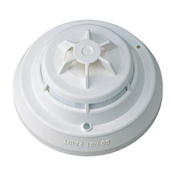
Figure 1
HFP-11 and HFPT-11
Fire Print Detectors And Nuisance Alarms
The neural network within each Model HFP-11 FirePrint detector
is optimized to reject the most common nuisance alarms for its
selected FirePrint Application; e.g. Parking Garage or Health Care.
If the detector is exposed to an excess level of smoke or aerosol
for an extended period of time, the detector is programmed to
make the "safe decision" and signal an alarm condition. Because
the amplitude and duration of deceptive phenomena are un-
bounded, the rule of thumb is to keep detectors as far as practi-
cal from sources that can produce an unusually large quantity of
smoke for about a minute. This effort during placement of detec-
tors within a FirePrint Application enhances the ability of FirePrint's
deceptive phenomena rejection. Avoid close proximity of detec-
tors to smoke sources such as oil burners, electric heaters, kitch-
ens, garages, and areas of high relative humidity where con-
densation may occur.
Air Currents
Before a detector can sense a fire, the products of combustion
or smoke must travel from the fire to the detector. This travel
is especially influenced by air currents; therefore, consider air
movement when designing the system. While combustion
products tend to rise, drafts from hallways, air diffusers, fans,
etc., may help or hinder the travel of combustion products to
the detector. When positioning a detector at a particular loca-
tion, give consideration to windows and doors, both open and
closed, to ventilating systems, both in and out of operation,
and to other factors influencing air movement. Do not install a
detector in the air stream of a room air supply diffuser. It is
better to position a detector closer to an air return.
The distance that products of combustion or smoke travel
from a fire to the detector is not usually the shortest linear
route. Combustion products or smoke usually rise to the ceil-
ing, then spread out. Average ceiling heights of 8 to 10 feet
do not abnormally affect detector response. High ceilings, lo-
cated in churches, warehouses, auditoriums, etc., do affect
detector response and should be considered.
Special Ceiling Construction Factors
Ceiling obstructions change the natural movement of air and
combustion products. Depending on the direction of smoke
travel, joists and beams can slow the movement of heated air
and smoke, while pockets between them can contain a re-
duced level of smoke. Take obstructions created by girders,
joists, beams, air conditioning ducts, or architectural design
into consideration when determining area protection. Refer
to the Initiating Devices chapter of NFPA Standard 72 for Lo-
cation and Spacing requirements for specific types of con-
struction; e.g. beam, suspended, level, sloped and peaked
ceilings.
Building T T T T T ec
Building
Building
Building
Building
Siemens
Siemens Industry
Siemens
Industry, , , , , Inc.
Industry
Industry
Siemens
Siemens
Industry
ec
echnologies Di
ec
hnologies Di
hnologies Division
hnologies Di
vision
vision
vision
ec
hnologies Di
vision
Inc.
Inc.
Inc.
Inc.
Advertisement

Related Manuals for Siemens HFPT-11


Summary of Contents for Siemens HFPT-11
-
Page 1: Installation Instructions
(sloped or flat, smooth or beamed). Siemens duced level of smoke. Take obstructions created by girders, Industry, Inc.’s extensive experience in the design of the sys-... - Page 2 HFPT-11 DETECTOR PLACEMENT operating. Based on the results of these checks, the LED indicator flashes Locate Model HFPT-11 on the ceiling, at least 4 inches from the following: the side walls. For an ideal, smooth ceiling condition, place the detectors at a maximum center spacing of 50 feet (2500 square feet).
- Page 3 TO NEXT BASE *The relay contacts are shown after System reset, which represents the non-alarm condition. Figure 2 **HFP-11/HFPT-11 is a polarity insensitive detector. Line 1 and Line 2 can be either line of the loop. Installation and Wiring Diagram...
- Page 4 Contact of smoke generate an alarm. (Refer to the FireFinder-XLS Siemens Industry, Inc. Product Service to order Detector System Manual, P/N 315-033744 for further explanation.) FS- Maintenance Kit, Model DMK-11. Do not disconnect the 250 panels indicate Maint Alert for any detector whose smoke thermal wires from the detector.
Need help?
Do you have a question about the HFPT-11 and is the answer not in the manual?
Questions and answers