Table of Contents
Advertisement
Quick Links
Advertisement
Table of Contents

Related Manuals for Supermicro SuperServer 6016T-MT


Summary of Contents for Supermicro SuperServer 6016T-MT
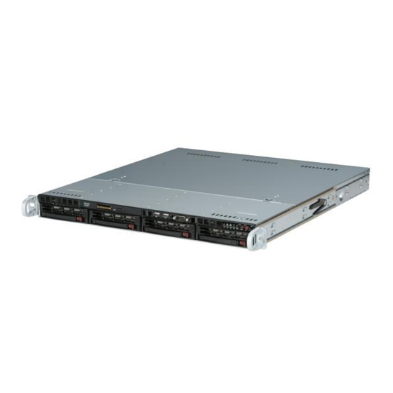
- Page 1 ® UPER 6016T-MT UPER ERVER USER’S MANUAL Revision 1.0a...
- Page 2 Please Note: For the most up-to-date version of this manual, please see our web site at www.supermicro.com. Super Micro Computer, Inc. ("Supermicro") reserves the right to make changes to the product described in this manual at any time and without notice. This product, including software, if any, and documentation may not, in whole or in part, be copied, photocopied, reproduced, translated or reduced to any medium or machine without prior written consent.
- Page 3 About This Manual This manual is written for professional system integrators and PC technicians. It provides information for the installation and use of the SuperServer 6016T-MT. In- stallation and maintenance should be performed by experienced technicians only. The SuperServer 6016T-MT is a 1U rackmount server based on the SC813MTQ- 520CB server chassis and the Super X8DTL-i serverboard.
- Page 4 SUPERSERVER 6016T-MT User's Manual Chapter 4: System Safety You should thoroughly familiarize yourself with this chapter for a general overview of safety precautions that should be followed when installing and servicing the SuperServer 6016T-MT. Chapter 5: Advanced Serverboard Setup Chapter 5 provides detailed information on the X8DTL-i serverboard, including the locations and functions of connectors, headers and jumpers.
- Page 5 Preface Notes...
-
Page 6: Table Of Contents
SUPERSERVER 6016T-MT User's Manual Table of Contents Chapter 1 Introduction Overview ......................1-1 Serverboard Features ..................1-2 Processor ......................1-2 Memory ......................1-2 Serial ATA ....................... 1-2 PCI Expansion Slots ..................1-2 Backpanel Ports ....................1-2 Server Chassis Features ................1-4 System Power .................... - Page 7 Table of Contents Checking the Drive Bay Setup ................ 2-9 Chapter 3 System Interface Overview ......................3-1 Control Panel Buttons ..................3-1 Reset ....................... 3-1 Power ......................3-1 Control Panel LEDs ..................3-2 Overheat/Fan Fail ................... 3-2 NIC2 ........................ 3-2 NIC1 ........................
- Page 8 SUPERSERVER 6016T-MT User's Manual Serverboard Layout ..................5-12 X8DTL-i Quick Reference ................5-13 Connector Defi nitions ................... 5-14 ATX Power Connector ................5-14 Processor Power Connector ..............5-14 PW_ON Connector ................... 5-14 Reset Connector ..................5-14 Power Fail LED ..................5-15 Overheat LED (OH) ..................
- Page 9 Table of Contents Rear UID LED ..................5-22 5-12 SATA Ports ....................5-23 SATA Ports ....................5-23 5-13 Installing Software ..................5-24 Supero Doctor III ................... 5-25 Chapter 6 Advanced Chassis Setup Static-Sensitive Devices .................. 6-1 Precautions ..................... 6-1 Unpacking ....................... 6-1 Control Panel ....................
- Page 10 SUPERSERVER 6016T-MT User's Manual Notes...
-
Page 11: Chapter 1 Introduction
Introduction Overview The SuperServer 6016T-MT is a 1U rackmount server designed for optimal space effi ciency and comprised of two main subsystems: the SC813MTQ-520CB 1U chas- sis and the X8DTL-i serverboard. Please refer to our web site for information on operating systems that have been certifi... -
Page 12: Serverboard Features
SATA drives are hot-swappable units. For more information on SATA HostRAID confi guration, please refer to the Intel SATA HostRAID User's Guide posted on our website at http://www.supermicro.com/support/manuals/. Note: You must have RAID set up to enable the hot-swap capability of the SATA drives. - Page 13 Chapter 1: Introduction Figure 1-1 . Intel 5500 Chipset: System Block Diagram Note: This is a general block diagram. Please see Chapter 5 for details. CPU1 CPU2 LGA1366 LGA1366 Port 0 Port Gen 2 x8 Gen 2 x4 Ports 1,2 Ports 9,10 Intel 5500...
-
Page 14: Server Chassis Features
The following is a general outline of the main features of the SC813MTQ-520CB chassis. System Power In the SuperServer 6016T-MT, the SC813MTQ-520CB chassis includes a single 520W power supply. Serial ATA Subsystem The SC813MTQ-520CB chassis was designed to support four SATA hard drives. -
Page 15: Contacting Supermicro
Super Micro Computer, Inc. 980 Rock Ave. San Jose, CA 95131 U.S.A. Tel: +1 (408) 503-8000 Fax: +1 (408) 503-8008 Email: marketing@supermicro.com (General Information) support@supermicro.com (Technical Support) Web Site: www.supermicro.com Europe Address: Super Micro Computer B.V. Het Sterrenbeeld 28, 5215 ML... - Page 16 UPER ERVER 6016T-MT User's Manual Notes...
-
Page 17: Chapter 2 Server Installation
Precautions in the next section. Preparing for Setup The box the SuperServer 6016T-MT was shipped in should include two sets of rail assemblies, six rail mounting brackets and the mounting screws you will need to install the system into the rack. Follow the steps in the order given to complete the installation process in a minimal amount of time. -
Page 18: Rack Precautions
UPER ERVER 6016T-MT User's Manual installation only in a Restricted Access Location (dedicated equipment rooms, service closets and the like). • This product is not suitable for use with visual display work place devices acccording to §2 of the the German Ordinance for Work with Visual Display Units. -
Page 19: Rack Mounting Considerations
Chapter 2: Server Installation Rack Mounting Considerations Ambient Operating Temperature If installed in a closed or multi-unit rack assembly, the ambient operating tempera- ture of the rack environment may be greater than the ambient temperature of the room. Therefore, consideration should be given to installing the equipment in an environment compatible with the manufacturer’s maximum rated ambient tempera- ture (Tmra). -
Page 20: Installing The System Into A Rack
Identifying the Sections of the Rack Rails You may have received rack rail hardware with the SuperServer 6016T-MT. (Two front inner rails should already be attached to the chassis.) This hardware consists of two rear inner rails that secure to the chassis, one on each side just behind the preinstalled front inner rails. -
Page 21: Installing The Rack Rails
Figure 2-1. Installing Rear Inner Chassis Rails Installing the Rack Rails Determine where you want to place the SuperServer 6016T-MT in the rack (see Rack and Server Precautions in Section 2-3). Position the chassis rail guides at the desired location in the rack, keeping the sliding rail guide facing the inside of the rack. -
Page 22: Installing The Server Into The Rack
UPER ERVER 6016T-MT User's Manual Installing the Server into the Rack You should now have rails attached to both the chassis and the rack unit. The next step is to install the server into the rack. Do this by lining up the rear of the chassis rails with the front of the rack rails. -
Page 23: Installing The Server Into A Telco Rack
Chapter 2: Server Installation Installing the Server into a Telco Rack To install the SuperServer 6016T-MT into a Telco type rack, use two L-shaped brackets on either side of the chassis (four total). First, determine how far the server will extend out the front of the rack. Larger chassis should be positioned to balance the weight between front and back. -
Page 24: Checking The Motherboard Setup
UPER ERVER 6016T-MT User's Manual Checking the Motherboard Setup After you install the 6016T-MT in the rack, you will need to open the unit to make sure the motherboard is properly installed and all the connections have been made. Accessing the Inside of the System Grasp the two handles on either side and pull the unit straight out until it locks (you will hear a "click"). -
Page 25: Checking The Drive Bay Setup
Chapter 2: Server Installation Checking the Drive Bay Setup Next, you should check to make sure the peripheral drives and the SATA drives and their backplane have been properly installed and all essential connections have been made. Checking the Drives All drives can be accessed from the front of the server. - Page 26 UPER ERVER 6016T-MT User's Manual Notes 2-10...
-
Page 27: Chapter 3 System Interface
Chapter 3: System Interface Chapter 3 System Interface Overview There are several LEDs on the control panel as well as others on the SATA drive carriers to keep you constantly informed of the overall status of the system as well as the activity and health of specifi... -
Page 28: Control Panel Leds
UPER ERVER 6016T-MT User's Manual Control Panel LEDs The control panel located on the front of the SC813MTQ-520CB chassis has fi ve LEDs. These LEDs provide you with critical information related to different parts of the system. This section explains what each LED indicates when illuminated and any corrective action you may need to take. -
Page 29: Power
Chapter 3: System Interface Power Indicates power is being supplied to the system's power supply units. This LED should normally be illuminated when the system is operating. Drive Carrier LEDs Each drive carrier has two LEDs. • Green: When illuminated, the green LED on the front of the drive carrier in- dicates drive activity. - Page 30 UPER ERVER 6016T-MT User's Manual Notes...
-
Page 31: Chapter 4 System Safety
System Safety Electrical Safety Precautions Basic electrical safety precautions should be followed to protect yourself from harm and the SuperServer 6016T-MT from damage: • Be aware of the locations of the power on/off switch on the chassis as well as the room's emergency power-off switch, disconnection switch or electrical outlet. -
Page 32: General Safety Precautions
UPER ERVER 6016T-MT User's Manual • This product may be connected to an IT power system. In all cases, make sure that the unit is also reliably connected to Earth (ground). • Serverboard Battery: CAUTION - There is a danger of explosion if the onboard battery is installed upside down, which will reverse its polarites (see Figure 4-1). -
Page 33: Esd Precautions
Chapter 4: System Safety • Remove any jewelry or metal objects from your body, which are excellent metal conductors that can create short circuits and harm you if they come into contact with printed circuit boards or areas where power is present. •... -
Page 34: Operating Precautions
UPER ERVER 6016T-MT User's Manual Operating Precautions Care must be taken to assure that the chassis cover is in place when the 6016T-MT is operating to assure proper cooling. Out of warranty damage to the system can occur if this practice is not strictly followed. Figure 4-1. -
Page 35: Chapter 5 Advanced Serverboard Setup
Chapter 5: Advanced Serverboard Setup Chapter 5 Advanced Serverboard Setup This chapter covers the steps required to install the X8DTL-i serverboard into the SC813MTQ-520CB chassis, connect the data and power cables and install add-on cards. All serverboard jumpers and connections are also described. A layout and quick reference chart are included in this chapter for your reference. -
Page 36: Unpacking
UPER ERVER 6016T-MT User's Manual Unpacking The serverboard is shipped in antistatic packaging to avoid electrical static dis- charge. When unpacking the board, make sure the person handling it is static protected. Serverboard Installation This section explains the fi rst step of physically mounting the X8DTL-i into the SC813MTQ-520CB chassis. -
Page 37: Connecting Cables
Chapter 5: Advanced Serverboard Setup Connecting Cables Now that the serverboard is installed, the next step is to connect the cables to the board. These include the data cables for the peripherals and control panel and the power cables. Connecting Data Cables The cables used to transfer data from the peripheral devices have been carefully routed to prevent them from blocking the fl... -
Page 38: Rear I/O Ports
UPER ERVER 6016T-MT User's Manual Figure 5-1. Control Panel Header Pins Ground x (Key) x (Key) Power On LED HDD LED NIC1 LED NIC2 LED OH/Fan Fail LED Vcc/Front UID LED Power Fail LED Ground Reset (Button) Ground Power (Button) Rear I/O Ports The I/O ports are color coded in conformance with the PC 99 specifi... -
Page 39: Installing The Processor And Heatsink
CPU socket cap is in place and none of the socket pins are bent; otherwise, contact your retailer immediately. • Refer to the Supermicro web site for updates on CPU support. Installing an LGA1366 Processor Press the socket clip to release... - Page 40 UPER ERVER 6016T-MT User's Manual After removing the plastic cap, use your thumb and the index fi nger to hold the CPU at the north and south center edges. Align the CPU key (the semi-circle cutout) with the socket key (the notch below the gold color dot on the side of the socket).
-
Page 41: Installing A Passive Cpu Heatsink
Chapter 5: Advanced Serverboard Setup Installing a Passive CPU Heatsink Warning: Two different heatsinks are included with the system: SNK- P00041 is for the CPU closest to the fans and hard drives while SNK- P0037P is for the other CPU (closest to the I/O ports). Screw#4 Notes: The serverboard comes with a heatsink bracket pre-in-... -
Page 42: Removing The Heatsink
UPER ERVER 6016T-MT User's Manual Removing the Heatsink Warning: We do not recommend that the CPU or the heatsink be re- moved. However, if you do need to remove the heatsink, please follow the instructions below prevent damage to the CPU or other components. Power down the system and unplug the power cord from the power supply. -
Page 43: Installing Memory Modules
Chapter 5: Advanced Serverboard Setup Installing Memory Modules Note: Check the Supermicro web site for recommended memory modules. CAUTION Exercise extreme care when installing or removing DIMM modules to prevent any possible damage. Installing & Removing DIMMs Press the release tabs Insert the desired number of DIMMs into the memory slots, starting with DIMM #1A. -
Page 44: Memory Support
UPER ERVER 6016T-MT User's Manual Memory Support The X8DTL-i supports up to 48 GB Registered ECC DDR3-1333/1066/800 MHz registered ECC or 24 GB of unbuffered ECC/non-ECC DDR3-1333/1066/800 SDRAM in 6 DIMM slots. Populating DIMMs Follow the tables below when installing memory. Populating DIMMs for Optimal Performance For One CPU (CPU1) Installed (Populate the CPU1 DIMM slots) Branch 0... -
Page 45: Adding Pci Cards
Chapter 5: Advanced Serverboard Setup Notes: Due to OS limitations, some operating systems may not show more than 4 GB of memory. Due to memory allocation to system devices, the amount of memory that remains available for operational use will be reduced when 4 GB of RAM is used. The reduction in memory availability is disproportional. -
Page 46: Serverboard Details
UPER ERVER 6016T-MT User's Manual Serverboard Details Serverboard Layout Figure 5-4. X8DTL-i Layout P2-DIMM3A FAN1/ JPW3 JPW2 CPU2 FAN KB/Mouse P2-DIMM2A JPW1 P2-DIMM1A JPI2C USB0/1 CPU2 CPU1 FAN2/ CPU1FAN JPL1 LAN1 FAN3 JPL2 X8DTL-i LAN2 FAN5 P1-DIMM1A FAN6 P1-DIMM2A P1-DIMM3A Slot 6: PCI-Express 2.0 x8 (in x16 slot) Slot 5: PCI-Express 2.0 x4 (in x8 slot) Intel... -
Page 47: X8Dtl-I Quick Reference
Chapter 5: Advanced Serverboard Setup X8DTL-i Quick Reference Jumper Description Default Setting JBT1 CMOS Clear Open (Normal) C1/JI SMB to PCI/PCI-E Slots Open/Open (Disabled) JPG1 VGA Enable/Disable Pins 1-2 (Enabled) JPL1/JPL2 LAN1/2 Enable Pins 1-2 (Enabled) Watch Dog Pins 1-2 (Reset) Connector Description COM1/COM2... -
Page 48: Connector Defi Nitions
UPER ERVER 6016T-MT User's Manual Connector Defi nitions ATX Power 24-pin Connector Pin Defi nitions Pin# Defi nition Pin # Defi nition ATX Power Connector +3.3V +3.3V The primary power supply connector -12V +3.3V (JPW1) on the X8DTL-i meets the SSI EPS 12V specifi... -
Page 49: Power Fail Led
Chapter 5: Advanced Serverboard Setup Power Fail LED PWR Fail LED Pin Defi nitions The Power Fail LED connection is Pin# Defi nition located on pins 5 and 6 of JF1. Re- fer to the table on the right for pin Ground defi... -
Page 50: Power On Led
UPER ERVER 6016T-MT User's Manual Power On LED The Power On LED connector is lo- Power LED Pin Defi nitions cated on pins 15 and 16 of JF1. This Pin# Defi nition connection is used to provide LED 5V Stby indication of power being supplied to Control the system. -
Page 51: Universal Serial Bus (Usb)
Chapter 5: Advanced Serverboard Setup USB Ports Pin Defi nitions (USB0/1/6) Pin# Defi nitions Universal Serial Bus (USB) There are two Universal Serial Bus ports located on the I/O panel and Ground fi ve additional USB headers located on the serverboard. The headers, USB Headers labeled USB2/3 and USB4/5, can be Pin Defi... -
Page 52: Onboard Speaker (Sp1)
UPER ERVER 6016T-MT User's Manual Onboard Speaker (SP1) Internal Buzzer Pin Defi nition The onboard speaker provides audible Pin# Defi nitions indications for various beep codes. Pin 1 Pos. (+) Beep In See the table on the right for pin defi ni- Pin 2 Neg. -
Page 53: Lan1/2 (Ethernet Ports)
Chapter 5: Advanced Serverboard Setup LAN1/2 (Ethernet Ports) Two gigabit Ethernet ports (desig- nated LAN1 and LAN2) are located beside the VGA port on the I/O back- plane. These ports accept RJ45 type cables. PWR SMB Pin Defi nitions Power SMB (I C) Header Pin# Defi... -
Page 54: 5-10 Jumper Settings
UPER ERVER 6016T-MT User's Manual 5-10 Jumper Settings Explanation of Jumpers To modify the operation of the serverboard, jumpers can be used Connector Pins to choose between optional settings. Jumpers create shorts between two pins to change the function of the con- Jumper nector. -
Page 55: Lan1/Lan2 Enable/Disable
Chapter 5: Advanced Serverboard Setup LAN1/LAN2 Enable/Disable LAN1/2 Enable/Disable Jumper Settings Change the setting of jumper JPL1 to Jumper Setting Defi nition enable or disable the LAN1 port and Pins 1-2 Enabled JPL2 to enable or disable the LAN2 Pins 2-3 Disabled port on the serverboard. -
Page 56: 5-11 Onboard Indicators
UPER ERVER 6016T-MT User's Manual 5-11 Onboard Indicators LAN LED (Connection Speed Indicator) LED Color Defi nition LAN1/LAN2 LEDs 10 Mb/s The Ethernet ports (located beside the Green 100 Mb/s VGA port) have two LEDs. On each Gb Amber 1 Gb/s LAN port, one LED indicates activity when blinking while the other LED may be green, amber or off to indicate the... -
Page 57: 5-12 Sata Ports
Chapter 5: Advanced Serverboard Setup 5-12 SATA Ports SATA Port Pin Defi nitions Pin # Defi nition SATA Ports Ground There are no jumpers to en- able the SATA ports, which are designated I-SATA0 ~ I-SATA5 Ground See the table on the right for pin defi... -
Page 58: 5-13 Installing Software
5-13 Installing Software After the hardware has been installed, you should fi rst install the operating system and then the drivers. The necessary drivers are all included on the Supermicro CDs that came packaged with your serverboard. Driver/Tool Installation Display Screen Note: Click the icons showing a hand writing on paper to view the readme fi... -
Page 59: Supero Doctor Iii
Chapter 5: Advanced Serverboard Setup Supero Doctor III The Supero Doctor III program is a Web-based management tool that supports remote management capability. It includes Remote and Local Management tools. The local management is called SD III Client. The Supero Doctor III program included on the CD-ROM that came with your serverboard allows you to monitor the environment and operations of your system. - Page 60 Supero Doctor III Interface Display Screen (Remote Control) Note: SD III Software Revision 1.0 can be downloaded from our Web Site at: ftp://ftp. supermicro.com/utility/Supero_Doctor_III/. You can also download the SDIII User's Guide at: <http://www.supermicro.com/PRODUCT/Manuals/SDIII/UserGuide.pdf>. For Linux, we will recommend using Supero Doctor II.
-
Page 61: Chapter 6 Advanced Chassis Setup
Chapter 6: Advanced Chassis Setup Chapter 6 Advanced Chassis Setup This chapter covers the steps required to install components and perform mainte- nance on the SC813MTQ-520CB chassis. For component installation, follow the steps in the order given to eliminate the most common problems encountered. If some steps are unnecessary, skip ahead to the step that follows. -
Page 62: Control Panel
UPER ERVER 6016T-MT User's Manual Figure 6-1. Chassis Front View Figure 6-2. Chassis Rear View Control Panel The control panel (located on the front of the chassis) must be connected to the JF1 connector on the motherboard to provide you with system control buttons and status indicators. -
Page 63: System Fans
BIOS. System Fan Failure If a fan fails, you will need to have it replaced with the same type. Contact your vendor or Supermicro for information on replacement fans. Drive Bay Installation/Removal Removing the Front Bezel If your system has a front bezel (optional) attached to the chassis, you must fi... -
Page 64: Sata Drive Installation
"slim" DVD-ROM drive will fi t into the 6016T-MT. Warning! Enterprise level hard disk drives are recommended for use in Supermicro chassis and servers. For information on recommended HDDs, visit the Supermicro Web site at http://www.supermicro.com/products/nfo/ fi les/storage/SAS-1-CompList-110909.pdf... -
Page 65: Sata Backplane
Chapter 6: Advanced Chassis Setup Installing/Removing SATA Drives To remove a carrier, push the release button located beside the drive LEDs. Swing the colored handle fully out and use it to pull the unit straight out (see Figure 6-5). Note: There is no onboard RAID support for SATA drives. Figure 6-5. - Page 66 UPER ERVER 6016T-MT User's Manual DVD-ROM Drive Installation The top cover of the chassis must be opened to gain full access to the DVD-ROM drive bay. The 6016T-MT accomodates only slim DVD-ROM drives. Side mounting brackets are needed to mount a slim DVD-ROM drive into the 6016T-MT server.You must power down the system before installing or removing a DVD-ROM drive.
-
Page 67: Power Supply
Chapter 6: Advanced Chassis Setup Power Supply The SuperServer 6016T-MT has a single 520 watt power supply. This power supply has the capability of operating at 100 - 240 input volts. Depress the main power button on the front of the chassis and then unplug the AC power cord to completely remove power from the system before removing the power supply. - Page 68 UPER ERVER 6016T-MT User's Manual Notes...
-
Page 69: Chapter 7 Bios
When an option is selected in the left frame, it is highlighted in white. Often a text message will accompany it. (Note: the AMI BIOS has default text messages built in. Supermicro retains the option to include, omit, or change any of these text messages.) The AMI BIOS Setup Utility uses a key-based navigation system called "hot keys". -
Page 70: Starting The Setup Utility
Warning! Do not upgrade the BIOS unless your system has a BIOS-related issue. Flashing the wrong BIOS can cause irreparable damage to the system. In no event shall Supermicro be liable for direct, indirect, special, incidental, or consequential damages arising from a BIOS update. If you have to update the BIOS, do not shut down or reset the system while the BIOS is updating. - Page 71 Chapter 7: BIOS • Build Date : This item displays the date when this BIOS was completed. Processor The AMI BIOS will automatically display the status of the processor used in your system: • CPU Type : This item displays the type of CPU used in the motherboard. •...
-
Page 72: Advanced Setup Confi Gurations
SUPERSERVER 6016T-MT User's Manual Advanced Setup Confi gurations Use the arrow keys to select Boot Setup and hit <Enter> to access the submenu items: Main Advanced Security Boot Exit Advanced Settings Configure BOOT Features. BOOT Feature Processor & Clock Options... - Page 73 Chapter 7: BIOS Wait For 'F1' If Error This forces the system to wait until the 'F1' key is pressed if an error occurs. The options are Disabled and Enabled. Hit 'Del' Message Display This feature displays "Press DEL to run Setup" during POST. The options are Enabled and Disabled.
- Page 74 SUPERSERVER 6016T-MT User's Manual Processor and Clock Options This submenu allows the user to confi gure the Processor and Clock settings. CPU Ratio If set to Manual, this option allows the user to set the ratio between the CPU Core Clock and the FSB Frequency.
- Page 75 Chapter 7: BIOS Simultaneous Multi-Threading (Available when supported by the CPU) Set to Enabled to use the Simultaneous Multi-Threading Technology, which will result in increased CPU performance. The options are Disabled and Enabled. Active Processor Cores Set to Enabled to use a processor's Second Core and beyond. (Please refer to Intel's web site for more information.) The options are All, 1 and 2.
- Page 76 SUPERSERVER 6016T-MT User's Manual DCA Technology This feature accelerates the performance of TOE devices. Note: A TOE device is a specialized, dedicated processor that is installed on an add-on card or a network card to handle some or all packet processing of this add-on card. For this moth- erboard, the TOE device is built inside the ESB 2 South Bridge chip.
- Page 77 Chapter 7: BIOS Channel Mirror - The motherboard maintains two identical copies of all data in memory for redundancy. Lockstep - The motherboard uses two areas of memory to run the same set of operations in parallel. Sparing - A preset threshold of correctable errors is used to trigger fail-over. The spare memory is put online and used as active memory in place of the failed memory.
- Page 78 SUPERSERVER 6016T-MT User's Manual Air Flow This is the air fl ow speed to the DIMM modules. Each step is one mm/ sec. The default is [1500]. Press "+" or "-" on your keyboard to change this value. Altitude This feature defi nes how many meters above or below sea level the system is located.
- Page 79 Chapter 7: BIOS Active State Power Management Select Enabled to start Active-State Power Management for signal transactions between L0 and L1 Links on the PCI Express Bus. This maximizes power-saving and transaction speed. The options are Enabled and Disabled. USB Functions This feature allows the user to decide the number of onboard USB ports to be en- abled.
- Page 80 SUPERSERVER 6016T-MT User's Manual Confi gure SATA#1 as This feature allows the user to select the drive type for SATA#1. The options are IDE, RAID and AHCI. (When the option-RAID is selected, the item-ICH RAID Code Base will appear. When the option-AHCI is selected, the item-SATA AHCI will be available.)
- Page 81 Chapter 7: BIOS If not, contact your manufacturer or install an ATA/133 IDE controller card that supports 48-bit LBA mode. The options are Disabled and Auto. Block (Multi-Sector Transfer) Block Mode boosts the IDE drive performance by increasing the amount of data transferred.
- Page 82 SUPERSERVER 6016T-MT User's Manual Select MWDMA0 to allow the BIOS to use Multi Word DMA mode 0. It has a data transfer rate of 4.2 MBs. Select MWDMA1 to allow the BIOS to use Multi Word DMA mode 1. It has a data transfer rate of 13.3 MBs.
- Page 83 Chapter 7: BIOS Plug & Play OS Selecting Yes allows the OS to confi gure Plug & Play devices. (This is not required for system boot if your system has an OS that supports Plug & Play.) Select No to allow the AMI BIOS to confi...
- Page 84 SUPERSERVER 6016T-MT User's Manual Remote Access Confi guration Remote Access This allows the user to enable the Remote Access feature. The options are Disabled and Enabled. If Remote Access is set to Enabled, the following items will display: Serial Port Number This feature allows the user decide which serial port to be used for Console Redi- rection.
- Page 85 Chapter 7: BIOS Hardware Health Monitor This feature allows the user to monitor system health and review the status of each item as displayed. CPU Overheat Alarm This option allows the user to select the CPU Overheat Alarm setting which de- termines when the CPU OH alarm will be activated to provide warning of possible CPU overheat.
- Page 86 ‘Temperature Tolerance’ is, and not the other way around. This results in better CPU thermal management. Supermicro has leveraged this feature by assigning a temperature status to certain thermal conditions in the processor (Low, Medium and High). This makes it easier for the user to understand the CPU’s temperature status, rather than by just simply...
- Page 87 Chapter 7: BIOS tion and allow the onboard fans to constantly run at full speed. The Options are: Disabled, 4-pin (Server), 4-pin (Workstation), 4-pin (Quiet), 4-pin (Super Quiet). Voltage Readings The following voltage readings will be displayed. CPU0 Vcore, CPU1 Vcore, 1.5V, 5V, 5VSB, 12V, -12V, 3.3Vcc, 3.3VSB, VBAT and Vtt ACPI Confi...
- Page 88 SUPERSERVER 6016T-MT User's Manual Headless Mode This feature is used to enable system to function without a keyboard, monitor and/ or mouse attached The options are Enabled and Disabled. ACPI Version Features The options are ACPI v1.0, ACPI v2.0 and ACPI v3.0. Please refer to ACPI's website for further explanation: http://www.acpi.info/.
- Page 89 Chapter 7: BIOS • Event Dir Type • Event Data. Clear BMC System Event Log Select OK and press the <Enter> key to clear the BMC system log. Select Cancel to keep the BMC System log. The options are OK and Cancel. Caution: Any cleared information is unrecoverable.
- Page 90 SUPERSERVER 6016T-MT User's Manual Gateway Address This is the IP address of the gateway in the network. This is usually a router. Mac Address The BIOS will automatically enter the Mac address of this machine; however it may be over-ridden. Mac addresses are 6 two-digit hexadecimal numbers (Base 16, 0 ~ 9, A, B, C, D, E, F) separated by dots.
-
Page 91: Security Settings
Chapter 7: BIOS BMC Watch Dog TimeOut [Min:Sec] This option appears if BMC Watch Dog Timer Action (above) is enabled. This is a timed delay in minutes or seconds, before a system power down or reset after an operating system failure is detected. The options are [5 Min], [1 Min], [30 Sec], and [10 Sec]. -
Page 92: Boot Confi Guration
SUPERSERVER 6016T-MT User's Manual Supervisor Password This item indicates if a Supervisor password has been entered for the system. "Not Installed" means a Supervisor password has not been used. User Password This item indicates if a user password has been entered for the system. "Not In- stalled"... - Page 93 Chapter 7: BIOS Main Advanced Security Boot Exit Boot Settings Specifies the Boot Device Boot Device Priority Priority sequence. Hard Disk Drives Removable Drives CD/DVD Drives : Move Enter : Select +/-/ : Value F10 : Save ESC : Exit F1 : General Help F8 : Fail-Safe Defaults F9 : Optimized Defaults...
-
Page 94: Exit Options
SUPERSERVER 6016T-MT User's Manual Exit Options Select the Exit tab from the AMI BIOS Setup Utility screen to enter the Exit BIOS Setup screen. Main Advanced Security Boot Exit Boot Settings Exit system setup after saving the Save Changes and Exit changes. -
Page 95: Appendix A Bios Post Error Codes
Appendix A: BIOS POST Error Codes Appendix A BIOS Post Error Codes During the POST (Power-On Self-Test) routines, which are performed each time the system is powered on, errors may occur. Non-fatal errors are those which, in most cases, allow the system to continue the boot-up process. - Page 96 SUPERSERVER 6016T-MT User's Manual Notes...
-
Page 97: Appendix B Installing Windows
South Bridge RAID Settings before you install the Windows OS and other software drivers. To confi gure RAID settings, please refer to RAID Confi guration User Guides posted on our website at www.supermicro.com/support/manuals. B-1 Installing the Windows OS to a RAID System Insert Microsoft's Windows Setup CD in the CD drive and the system will start booting up from CD. - Page 98 fi les and then continue with the installation. After the Windows installation is complete, the system will automatically reboot. Insert the Supermicro setup CD that came with your motherboard into the CD drive during system boot, and the main screen will display.
-
Page 99: Appendix C System Specifi Cations
Appendix C: System Specifi cations Appendix C System Specifi cations Processors Two Intel® 5500 Series processors in LGA1366 sockets Note: please refer to our website for details on supported processors. Chipset Intel 5500/ICH10R BIOS 32 Mb AMI SPI Flash ROM Memory Capacity Six DIMM slots that can support up to 48 GB of ECC registered DDR3- 1333/1066/800 SDRAM or 24 GB of ECC/non-ECC unbuffered DDR3-... - Page 100 UPER ERVER 6016T-MT User's Manual Weight Gross Weight: 38 lbs. (17.3 kg.) System Cooling Four 4-cm high-performance fans System Input Requirements AC Input Voltage: 100-240 VAC Rated Input Current: 5A max. (100-240V) Rated Input Frequency: 50 to 60 Hz Power Supply Rated Output Power: 520W (Part# PWS-521-1H) Rated Output Voltages: +3.3V (16A), +5V (20A), +12V (39A), -12V (0.5A),...
- Page 101 Appendix C: System Specifi cations Notes...
- Page 102 ERVER 6016T-MT User's Manual (continued from front) The products sold by Supermicro are not intended for and will not be used in life support systems, medical equipment, nuclear facilities or systems, aircraft, aircraft devices, aircraft/emergency com- munication devices or other critical systems whose failure to perform be reasonably expected to result in signifi...
Need help?
Do you have a question about the SuperServer 6016T-MT and is the answer not in the manual?
Questions and answers