Sign In
Upload
Download
Table of Contents
Contents
Add to my manuals
Delete from my manuals
Share
URL of this page:
HTML Link:
Bookmark this page
Add
Manual will be automatically added to "My Manuals"
Print this page
×
Bookmark added
×
Added to my manuals
Manuals
Brands
ABB Manuals
Power distribution unit
SafeRing 36
Installation and operating instructions manual
ABB SafeRing 36 Installation And Operating Instructions Manual
Hide thumbs
1
Table Of Contents
2
3
4
5
6
7
8
9
10
11
12
13
14
15
16
17
18
19
20
21
22
23
24
page
of
24
Go
/
24
Contents
Table of Contents
Bookmarks
Table of Contents
Table of Contents
General Description
Description of Functions
Dimensional Drawings
Side Connections
Transport and Handling
By Receiving Inspection
Storage
Technical Data
Electrical Data
Fuse Table
Installation
Cable Compartment
Cable Connection
Relay and Current Transformers for Relay Protection
Gas Pressure
Operation
Operating Conditions
Operation
Switch Disconnector, C-Module
Earthing Switch, C-Module
Switch-Fuse Combination
Switch-Disconnector, F-Module
Earthing Switch, F-Module
Vacuum Circuit-Breaker, V-Module
Installation and Replacement of Fuse Links
Additional Equipment
Motor Operation and Auxiliary Switches
Capacitive Voltage Indication
Current Measuring
Side Extension
Ronis Key Interlock
Padlocking Device
Short Circuit Indication
Maintenance
Control and Monitoring the Gas
Environmental Certification
Advertisement
Quick Links
1
Electrical Data
2
Technical Data
3
Installation
4
Operation
5
Maintenance
Download this manual
1VDD006116 GB
1VDD006116 GB
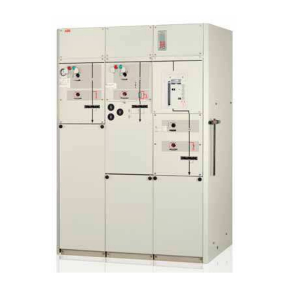
SafeRing / SafePlus 36kV
Installation and operating instructions
Table of
Contents
Previous
Page
Next
Page
1
2
3
4
5
Advertisement
Table of Contents
Need help?
Do you have a question about the SafeRing 36 and is the answer not in the manual?
Ask a question
Questions and answers
Related Manuals for ABB SafeRing 36
Power distribution unit ABB TruFit 300kVA Installation Manual
(34 pages)
Power distribution unit ABB RELION 670 Series Installation Manual
(112 pages)
Power distribution unit ABB RER620 Technical Manual
Advanced recloser protection and control (584 pages)
Power distribution unit ABB Relion 670 Series Applications Manual
Bay control, version 2.1 ansi (528 pages)
Power distribution unit ABB RET670 Commissioning Manual
Transformer protection version 2.1 ansi (254 pages)
Power distribution unit ABB UniGear ZS1 Installation, Operation And Maintenance Instructions Manual
(131 pages)
Power distribution unit ABB DPU 1500R Instruction Book
Distribution protection unit (180 pages)
Power distribution unit ABB TPU-2000R Manual
Transformer protection unit (8 pages)
Power distribution unit ABB Relion 630 Series Operation Manual
Protection and control (108 pages)
Power distribution unit ABB RGU-10 B Manual
Residual current device and monitor (3 pages)
Power distribution unit ABB RED670 Product Manual
Line differential protection, pre-configured, relion 670 series (101 pages)
Power distribution unit ABB RELION REX640 Installation Manual
(100 pages)
Power distribution unit ABB RES670 Applications Manual
Relion 670 series phasor measurement unit (382 pages)
Power distribution unit ABB Relion 650 Series Technical Manual
Bay control (754 pages)
Power distribution unit ABB Relion 670 Series Technical Reference Manual
Line differential protection ansi (1232 pages)
Power distribution unit ABB REQ650 Commissioning Manual
Relion 650 series, breaker protection (148 pages)
This manual is also suitable for:
Safeplus 36
Table of Contents
Save PDF
Print
Rename the bookmark
Delete bookmark?
Delete from my manuals?
Login
Sign In
OR
Sign in with Facebook
Sign in with Google
Upload manual
Upload from disk
Upload from URL


Need help?
Do you have a question about the SafeRing 36 and is the answer not in the manual?
Questions and answers