
Related Manuals for 3e Technologies International AirGuard 3e-525A-3

Summary of Contents for 3e Technologies International AirGuard 3e-525A-3
- Page 1 � AirGuard™ Wireless Access Point User's Guide Model 3e-525A–3 3e Technologies International 700 King Farm Blvd., Suite 600 Rockville, MD 20850 (301) 670-6779 www.3eti.com 29000167-001 B publ. 10/18/05...
- Page 2 This page intentionally left blank.
- Page 3 3e Technologies International's AirGuard™ Wireless Access Point User's Guide Model 3e-525A–3...
- Page 4 International. 3e Technologies International reserves the right to revise this documentation and to make changes in content from time to time without obligation on the part of 3e Technologies International to provide notification of such revision or change. 3e Technologies International provides this documentation without warranty, term or condition of any kind, either implied or expressed, including, but not limited to, the implied warranties, terms, or conditions of merchantability, satisfactory quality, and fitness for a particular purpose.
-
Page 5: Table Of Contents
Table of Contents Chapter 1: Introduction....................1 Basic Features ......................2 Wireless Basics......................3 802.11b ........................3 802.11g........................3 802.11a ........................3 802.11b/g Mixed......................3 802.11g Super and 802.11a Turbo ................4 Network Configuration ..................4 Access Point Configurations..................4 Possible AP Topologies..................5 Bridging ........................6 Default Configuration.....................6 Data Encryption and Security................6 SSID ...........................6 WEP ...........................6 WPA/WPA2 with TKIP/ AES-CCMP..............6... - Page 6 FIPS 802.11i ......................34 Dynamic Key Exchange ..................35 No Encryption (non-FIPS) .................36 Static WEP Encryption (non-FIPS) ..............36 802.11i and WPA (non-FIPS) ................38 Wireless VLAN ......................40 MAC Address Filtering ..................41 Rogue AP Detection ....................42 Advanced........................43 Wireless Bridge......................43 Services Settings.......................44 DHCP Server ......................44 Subnet Roaming.....................45 SNMP Agent......................46 Misc Service......................47...
- Page 7 Virtual Server ......................75 Demilitarized Zone (DMZ) ..................76 Advanced Firewall ....................77 Chapter 5: Wireless Bridge Configuration ..............79 Introduction ......................79 Wireless Bridge — General ..................80 Auto-forming Wireless Bridging ..............80 Manual Bridging ....................82 Monitoring ......................83 Wireless Bridge — Radio..................83 Wireless Bridge — Encryption................86 Setting Up Bridging Type ..................87 Point-to-Point Bridge Configuration ..............87 Point-to-Point Bridging Setup Guide - Manual Mode........88...
- Page 8 29000167-001 B...
-
Page 9: Chapter 1: Introduction
3e-525A–3 Wireless Access Point Chapter 1: Introduction Chapter 1: Introduction This manual covers the installation and operation of the 3e Technolo- gies International’s 3e–525A–3 Wireless Access Point. The 3e–525A–3 is a ruggedized access point/gateway/bridge which is intended for use in industrial and external environments. It accommodates 802.11a/b/g, 802.11g Super, and 802.11a Turbo WLAN access and uses Power over Ethernet (PoE) access to the Ethernet WAN to eliminate the need for internal access point power supply units (AC-DC converters) and 110-... -
Page 10: Basic Features
3e-525A–3 Wireless Access Point Chapter 1: Introduction ated using a FIPS-approved RNG, with the output of the RNG used as in- put for the creation on non-weak keys for the algorithm. This ensures that keys are destroyed from storage in accordance with FIPS requirements, both after use (i.e. -
Page 11: Wireless Basics
3e-525A–3 Wireless Access Point Chapter 1: Introduction Wireless Basics Wireless networking uses electromagnetic radio frequency waves to transmit and receive data. Communication occurs by establishing radio links between the wireless access point and devices configured to be part of the WLAN. The 3e–525A–3 incorporates WiFi standard FIPS 140-2 security for wireless communication. -
Page 12: 802.11G Super And 802.11A Turbo
3e-525A–3 Wireless Access Point Chapter 1: Introduction 802.11g Super and 802.11a Turbo 802.11g Super and 802.11a Turbo technologies provide speed and throughput of more than double standard wireless LAN technologies in networking products such as PCs, access points, routers and PC cards. It is very helpful to users who require additional bandwidth (over stan- dard WLAN technologies) that results in higher throughput necessary for a variety of functions such as:... -
Page 13: Possible Ap Topologies
3e-525A–3 Wireless Access Point Chapter 1: Introduction Possible AP Topologies 1. An access point can be used as a stand-alone AP without any connection to a wired network. In this configuration, it simply provides a stand-alone wireless network for a group of wireless devices. -
Page 14: Bridging
3e-525A–3 Wireless Access Point Chapter 1: Introduction Bridging The wireless bridging function in the 3e–525A–3 allows use as a bridge, in a number of alternate configurations, including the following popular configurations: • Point-to-point bridging of 2 Ethernet Links; • Point-to-multipoint bridging of several Ethernet links; •... -
Page 15: Aes And 3Des
3e-525A–3 Wireless Access Point Chapter 1: Introduction tion, the Temporal Key Integrity Protocol (TKIP) and WEP 128-bit encryp- tion keys. Finally, a message integrity check (MIC) is used to prevent an attacker from capturing and altering or forging data packets. In addition, it can employ a form of AES called AES-CCMP. - Page 16 3e-525A–3 Wireless Access Point Chapter 1: Introduction Four major categories or primary functions of 802.11i are invoked within 3eTI products, including the wireless client devices, wireless ac- cess points (3e-525A2.3), and the security server. These primary functions of 802.11i include: •...
-
Page 17: Wireless Vlan
3e-525A–3 Wireless Access Point Chapter 1: Introduction – it provides keying material to implement the group key handshake within 802.11i 3eTI implements the 4-way handshake within its wire- less product line per the 802.11i specification, again with absolutely no custom modifications, in order to maximize interoperability with 3 party 802.11i and WPA2 compliant equipment. -
Page 18: Mac Address Filtering
3e-525A–3 Wireless Access Point Chapter 1: Introduction 3e-525A3 supports up to 16 VLANs. When VLAN is enabled, all data coming out of the WAN port is VLAN-tagged, which means an external network unit such as a router, switch, or a VLAN-enabled computer has to be used to terminate the VLAN traffic. -
Page 19: Operator Authentication And Management
3e-525A–3 Wireless Access Point Chapter 1: Introduction Operator Authentication and Management Authentication mechanisms are used to authenticate an operator ac- cessing the device and to verify that the operator is authorized to assume the requested role and perform services within that role. The 3e-525A-3 provides authentication services for all users of the wireless network when they first attempt to connect. -
Page 20: 3E-525A-3 Navigation Options
3e-525A–3 Wireless Access Point Chapter 1: Introduction Chapter 1: Introduction 3e–525A–3 Navigation Options ACCESS POINT GATEWAY Non FIPS 140-2 FIPS 140-2 Non FIPS 140-2 FIPS 140-2 System Configuration System Configuration System Configuration System Configuration General General General General Operating Mode Operating Mode Operating Mode Operating Mode... -
Page 21: Chapter 2: Hardware Installation
Chapter 2: Hardware Installation Chapter 2: Hardware installation Preparation for Use The 3e Technologies International's 3e–525A–3 Wireless Access Point requires physical mounting and installation on the site, following a pre- scribed placement design to ensure optimum operation and roaming. FCC Regulations require that the 3e–525A–3 be professionally installed by an installer certified by the National Association of Radio and Telecommunications Engineers or equivalent institution. -
Page 22: Installation Instructions
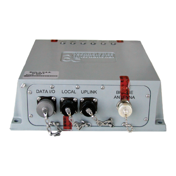
3e-525A–3 Wireless Access Point Chapter 2: Hardware Installation • 3e-RK1 reset kit • 3e-OPK-3 outdoor protection kit The bridge antenna port is used when configuring the unit to be used as a bridge. The port uses an omni-directional antenna. The 3e–525A–3 can be mounted outdoors on a high post to achieve the best bridge result.If mounted outdoors, the outdoor protection kit must be used to prevent lightning damage. -
Page 23: Cabling
3e-525A–3 Wireless Access Point Chapter 2: Hardware Installation Card. This software does not have WPA/WPA2 authentication modes but can be used with 3eTI proprietary encryption modes: AES, 3DES, and Dynamic Key Exchange (DKE). – 3e-010F-C-2 Crypto Client software for use with Intel® PRO/ Wireless 2200BG or 2915ABG Network Connection –... -
Page 24: Outdoor Protection Kit Installation
3e-525A–3 Wireless Access Point Chapter 2: Hardware Installation Connect Connect RF Antenna RF Antenna for AP for AP Connect RFAntenna for Bridge/ Repeater LAN "Local" WAN "Uplink" Ethernet Ethernet Port Port / PoE 110V Power Power Injector Ethernet switch/hub Outdoor Protection Kit Installation If any portion of this system (3e–525A–3 enclosure, antennas, cables etc.) is mounted outdoors, it is strongly recommended that the Outdoor Protection Kit (3e-OPK-3) for this product be used. -
Page 25: Earth Ground Connection
3e-525A–3 Wireless Access Point Chapter 2: Hardware Installation ! WARNING Do not attempt to install any outdoor equipment dur- ing hazardous conditions such as a thunderstorm, where lightning could strike the equipment or installer. Failure to follow this warning could result in injury or death. - Page 26 3e-525A–3 Wireless Access Point Chapter 2: Hardware Installation To install the lightning arrestors to the 3e–525A-3, attach one end of the lightning arrestor to the 3e–525A–3's N connector. Make sure that the lightning arrestor with the 12-inch wire is mounted closer to the ground stud (see figure).
-
Page 27: The Indicator Lights
3e-525A–3 Wireless Access Point Chapter 2: Hardware Installation The Indicator Lights The top panel of the 3e–525A–3 contains a set of indicator lights (Light Emitting Diodes or LEDs) that help describe the state of various network- ing and connection operations. Description Power The Power indicator LED informs you when the gate-... -
Page 28: External Reset Kit
3e-525A–3 Wireless Access Point Chapter 2: Hardware Installation External Reset Kit The external reset kit (3e-RK1) is an accessory for the 3e–525A–3. You can use this device to reboot the unit or reset the unit to its factory de- fault. CAUTION: The 3e–RK1 should be available to and used by an autho- rized Crypto Officer only. -
Page 29: Chapter 3: Access Point Configuration
3e–525A–3 Wireless Access Point Chapter 3: Access Point Configuration Chapter 3: Access Point Configuration Introduction The 3e–525A–3 comes with the capability to be configured as an access point. As it incorporates two separate 802.11 wireless cards, one for configuring a local WLAN and one for use in bridging, it can also be configured for bridging, either with access point or gateway configuration on the WLAN side. -
Page 30: Initial Setup Using The "Local" Port
3e–525A–3 Wireless Access Point Chapter 3: Access Point Configuration Initial Setup using the “Local” Port Plug one end of an RJ-45 Ethernet cable to the LAN port of the 3e–525A–3 (see page 11) and the other end to an Ethernet port on your laptop. -
Page 31: System Configuration
3e–525A–3 Wireless Access Point Chapter 3: Access Point Configuration On your computer, pull up a browser window and put the de- fault URL for the 3e–525A–3 Local LAN in the address line. (https:// 192.168.15.1) You will be asked for your User Name and Password. The default is "CryptoOfficer"... -
Page 32: Operating Mode
3e–525A–3 Wireless Access Point Chapter 3: Access Point Configuration Go next to the System Configuration — Operating Mode page. Operating Mode This screen allows you to set the operating mode to either Wireless Access Point/Bridge or Gateway/Bridge mode. You only need to visit this page if you will be changing from Access Point to Gateway, or if you want to change your submode. - Page 33 3e–525A–3 Wireless Access Point Chapter 3: Access Point Configuration support IPv6 are disabled such as DHCP server and WPA-802.1x When in IPv6 mode, the AP can be accessed from the management port using IP address 192.168.15.1. This is the default IP address and it can not be changed.
-
Page 34: Wan
3e–525A–3 Wireless Access Point Chapter 3: Access Point Configuration Click the entry on the left hand navigation panel for System Configu- ration — WAN. This directs you to the System Configuration — WAN screen. If not using DHCP to get an IP address, input the static IP information that the access point requires in order to be managed from the wired LAN. -
Page 35: Lan
3e–525A–3 Wireless Access Point Chapter 3: Access Point Configuration Click the entry on the left hand navigation panel for System Configu- ration — LAN. This directs you to the System Configuration — LAN screen. This sets up the default numbers for the four octets for a possible pri- vate LAN function for the access point. -
Page 36: Wireless Access Point Configuration
3e–525A–3 Wireless Access Point Chapter 3: Access Point Configuration Wireless Access Point Configuration General Wireless Setup allows your computer’s PC Card to communicate with the access point. Once you have completed wireless access point configu- ration, you can complete the rest of the configuration wirelessly unless you will be employing the FIPS 140-2 secure mode, assuming that you have installed and configured a wireless PC card on your computer. - Page 37 3e–525A–3 Wireless Access Point Chapter 3: Access Point Configuration Select the wireless mode from the drop-down list. You can choose from the following options: • 802.11b • 802.11g • 802.11g Super • 802.11b/g Mixed • 802.11a • 802.11a Turbo You can assign a channel number to the AP (if necessary) and modify the Tx Pwr Mode.
- Page 38 3e–525A–3 Wireless Access Point Chapter 3: Access Point Configuration Tx Pwr Mode and Fixed Pwr Level: The Tx Power Mode defaults to Auto, giving the largest range of radio transmission available under nor- mal conditions. As an option, the AP's broadcast range can be limited by setting the Tx Power Mode to Fixed and choosing from 1-5 for Fixed Pwr Level (1 being the shortest distance.) Finally, if you want to prevent any radio frequency transmission, set Tx Pwr Mode to Off.
-
Page 39: Security
3e–525A–3 Wireless Access Point Chapter 3: Access Point Configuration Security The Wireless Access Point — Security screen displays a default factory setting of no encryption, but for security reasons it will not com- municate to any clients unless the encryption is set by the CryptoOfficer. There are different encryption options for the AP in FIPS Mode and in non-FIPS Mode. -
Page 40: Static Aes Key
3e–525A–3 Wireless Access Point Chapter 3: Access Point Configuration Static AES Key The Advanced Encryption Standard (AES) was selected by National Institute of Standards and Technology (NIST) in October 2000 as an up- grade from the previous DES standard. AES uses a 128-bit block cipher algorithm and encryption technique for protecting computerized infor- mation. -
Page 41: Static 3Des Key
3e–525A–3 Wireless Access Point Chapter 3: Access Point Configuration Static 3DES Key To use 3DES, enter a 192-bit key as 48 hexidecimal digit (0-9, a-f, or A-F). The Key Generator button automatically generates a randomized key of the appropriate length. This key is initially shown in plain text so the user has the opportunity to copy the key. -
Page 42: Fips 802.11I
3e–525A–3 Wireless Access Point Chapter 3: Access Point Configuration FIPS 802.11i If you wish to use FIPS 802.11i on the 3e–525A–3, enable either Pre- shared Key Settings or 802.1x Settings. If you are a SOHO user, selecting pre-shared key means that you don’t have the expense of installing a Radius Server. -
Page 43: Dynamic Key Exchange
3e–525A–3 Wireless Access Point Chapter 3: Access Point Configuration Dynamic Key Exchange Dynamic key management requires the installation of the 3e-030 Security Server software which resides on a self-contained workstation connected to the 3e–525A–3 over the WAN port. The Security Server soft- ware configuration includes: obtaining a root certificate from a Certificate Authority (CA) like Microsoft;... -
Page 44: No Encryption (Non-Fips)
3e–525A–3 Wireless Access Point Chapter 3: Access Point Configuration No Encryption (non-FIPS) In order to the 3e–525A–3 with no encryption, you must actively select None and click Apply. A screen will appear, asking if you really want to operate in Bypass mode. If you answer Yes, no encryption will be applied. - Page 45 3e–525A–3 Wireless Access Point Chapter 3: Access Point Configuration Utilities exist for scanning for networks and logging all the networks it runs into—including the real SSIDs, the access point’s MAC address, the best signal-to-noise ratio encountered, and the time the user crossed into the network’s space.
-
Page 46: I And Wpa (Non-Fips)
3e–525A–3 Wireless Access Point Chapter 3: Access Point Configuration 802.11i and WPA (non-FIPS) Wi-Fi Protected Access or WPA was designed to enable use of wire- less legacy systems employing WEP while improving security. WPA uses improved data encryption through the temporal key integrity protocol (TKIP) which scrambles keys using a hashing algorithm and, by adding an integrity-checking feature, ensures that the keys haven’t been tam- pered with. - Page 47 3e–525A–3 Wireless Access Point Chapter 3: Access Point Configuration If you will be using MAC Address filtering, navigate next to the MAC Address Filtering screen. 29000167-001 B...
-
Page 48: Wireless Vlan
3e–525A–3 Wireless Access Point Chapter 3: Access Point Configuration Wireless VLAN When VLAN is enabled, all data coming out of the WAN port is VLAN-tagged, which means an external network unit such as a router, switch, or a VLAN-enabled computer has to be used to terminate the VLAN traffic. -
Page 49: Mac Address Filtering
3e–525A–3 Wireless Access Point Chapter 3: Access Point Configuration MAC Address Filtering The Wireless Access Point — MAC Address Filtering screen is used to set up MAC address filtering for the 3e–525A–3 device. The factory de- fault for MAC Address filtering is Disabled. If you enable MAC Address filtering, you should also set the toggle for Filter Type. -
Page 50: Rogue Ap Detection
3e–525A–3 Wireless Access Point Chapter 3: Access Point Configuration Rogue AP Detection The Wireless Access Point — Rogue AP Detection screen allows the network administrator to set up rogue AP detection. Enable rogue AP detection and enter the MAC Address of each AP in the network that you want the AP being configured to accept as a trusted AP. -
Page 51: Advanced
3e–525A–3 Wireless Access Point Chapter 3: Access Point Configuration Advanced The Wireless Access Point — Advanced screen allows you to enable or disable load balancing and to control layer 2 isolation. Load balancing is enabled by default. The load balancing feature bal- ances the wireless clients between APs. -
Page 52: Services Settings
3e–525A–3 Wireless Access Point Chapter 3: Access Point Configuration Services Settings DHCP Server The Service Settings — DHCP Server screen is used for configur- ing the DHCP server function accessible from the Local LAN port. The default factory setting for the DHCP server function is enabled. You can disable the DHCP server function, if you wish, but it is not recommended. -
Page 53: Subnet Roaming
3e–525A–3 Wireless Access Point Chapter 3: Access Point Configuration Subnet Roaming The 3e-525A supports subnet roaming with 3eTI's subnet roaming coor- dinator server installed. Subnet roaming occurs when a user roams to an access point that is connected to a different subnet than its home subnet. If subnet roaming is supported by the wireless infrastructure, the client is able to continue its network connectivity without having to change its IP address. -
Page 54: Snmp Agent
3e–525A–3 Wireless Access Point Chapter 3: Access Point Configuration SNMP Agent The Service Settings — SNMP Agent screen allows you to set up an SNMP Agent. The agent is a software module that collects and stores management information for use in a network management system. The 3e–525A–3's integrated SNMP agent software module translates the device’s management information into a common form for interpretation by the SNMP Manager, which usually resides on a network administra-... -
Page 55: Misc Service
3e–525A–3 Wireless Access Point Chapter 3: Access Point Configuration The SNMP configuration consists of several fields, which are ex- plained below: • Community –The Community field for Get (Read Only), Set (Read & Write), and Trap is simply the SNMP terminology for “password”... -
Page 56: User Management
3e–525A–3 Wireless Access Point Chapter 3: Access Point Configuration User Management List All Users The User Management — List All Users screen lists the Crypto Of- ficer and administrator accounts configured for the unit. You can edit or delete users from this screen. If you click on Edit, the User Management —... -
Page 57: Add New User
3e–525A–3 Wireless Access Point Chapter 3: Access Point Configuration Add New User The User Management — Add New User screen allows you to add new Administrators and CryptoOfficers, assigning and confirming the password. The screen shown above is the screen as it will appear in FIPS 140- 2 mode. -
Page 58: User Password Policy (Fips Mode Only)
3e–525A–3 Wireless Access Point Chapter 3: Access Point Configuration User Password Policy (FIPS Mode Only) The User Management — User Password Policy screen allows you to enable a Password Complexity Check when you are in FIPS 140-2 mode. The definition of a complex password is a password that contains charac- ters from 3 of the following 4 groups: uppercase letters, lowercase letters, numerals, and symbols. -
Page 59: Monitoring/Reports
3e–525A–3 Wireless Access Point Chapter 3: Access Point Configuration Monitoring/Reports This section gives you a variety of lists and status reports. Most of these are self-explanatory. System Status The Monitoring/Report — System Status screen displays the status of the 3e–525A–3 device, the network interface, and the routing table. There are some pop-up informational menus that give detailed infor- mation about CPU, PCI, Interrupts, Process, and Interfaces. -
Page 60: Bridging Status
3e–525A–3 Wireless Access Point Chapter 3: Access Point Configuration Bridging Status The Monitoring/Report — Bridging Status screen displays the Eth- ernet Port STP status, Ethernet DSL Port STP status, Wireless Port STP status, and Wireless Bridging information. 29000167-001 B... -
Page 61: Bridge Site Map
3e–525A–3 Wireless Access Point Chapter 3: Access Point Configuration Bridge Site Map The Bridge Site Map shows the spanning tree network topology of both wired and wireless nodes connected to the network. The root STP node is always on top and the nodes of the hierarchy are displayed below it. -
Page 62: Wireless Clients
3e–525A–3 Wireless Access Point Chapter 3: Access Point Configuration Wireless Clients The Monitoring/Report — Wireless Clients screen displays the MAC Address of all wireless clients and their signal strength and transmit rate. The screen shown here emulates the FIPS 140-2 setup and contains a column for EMCON response. -
Page 63: Adjacent Ap List
3e–525A–3 Wireless Access Point Chapter 3: Access Point Configuration Once the transmit power is re-enabled and clients re-associate to the AP, EMCON information is maintained for them. If a new client that wasn't associated previously associates with the AP after the EMCON mode, its EMCON status appears as "-", which indicates the status record is not applicable. -
Page 64: Dhcp Client List
3e–525A–3 Wireless Access Point Chapter 3: Access Point Configuration DHCP Client List The Monitoring/Report — DHCP Client List screen displays all clients currently connected to the 3e–525A–3 via DHCP server, including their hostnames, IP addresses, and MAC Addresses. The DHCP Client list constantly collects entries. To remove entries from the list, check mark the Revoke Entry selection and click Remove to confirm the action. -
Page 65: Web Access Log
3e–525A–3 Wireless Access Point Chapter 3: Access Point Configuration Web Access Log The Web Access Log displays system facility messages with date and time stamp for any actions involving web access. For example, this log re- cords when you set encryption mode, change operating mode, etc., using the web browser. -
Page 66: Auditing
3e–525A–3 Wireless Access Point Chapter 3: Access Point Configuration Auditing The 3e-525A-3 collects audit data and provides an interface for au- thorized administrators to review generated audit records. It generates records for two separate classes of events: authentication/access to the system, and actions taken directly on the system. -
Page 67: Report Query
3e–525A–3 Wireless Access Point Chapter 3: Access Point Configuration Report Query The Auditing—Report Query screen allows you to query on report based on start time, end time, MAC address, or unique record IDs. Configuration The Auditing—Configuration screen is used to configure the auditing settings. - Page 68 3e–525A–3 Wireless Access Point Chapter 3: Access Point Configuration Event Type Description Audit Log Configuration Modified Any modification to the audit log configuration (enable/disable, recorded event types, etc) will trig- ger the creation of an audit record. Key Transfer Error Any error detected during the dynamic key exchange, either to the station or the authentication...
-
Page 69: System Administration
3e–525A–3 Wireless Access Point Chapter 3: Access Point Configuration System Administration The System administration screens contain administrative functions. The screens and functions are detailed in the following section. System Upgrade The System Administration — System Upgrade screen gives you the ability to upload updates to the 3e–525A–3 device’s firmware as they be- come available. -
Page 70: Local Configuration Upgrade
3e–525A–3 Wireless Access Point Chapter 3: Access Point Configuration Local Configuration Upgrade On the System Administration — System Upgrade screen, click on the Local Configuration Upgrade tab to upload and download configura- tion files to access points connected to the network. To upload a configuration file, select the file using the browse but- ton and enter the passphrase for that file. -
Page 71: Remote Configuration Upgrade
3e–525A–3 Wireless Access Point Chapter 3: Access Point Configuration Remote Configuration Upgrade On the System Administration — System Upgrade screen, click on the Remote Configuration Upgrade tab to upload and download config- uration files to access points in remote locations which are not configured. This remote configuration upgrade feature allows you to selectively transfer a configuration file to other APs. - Page 72 3e–525A–3 Wireless Access Point Chapter 3: Access Point Configuration To create a randomly generated bridging configuration file, click Generate. A new configuration is created in a temporary file and an Install button appears. In order to transfer this file, select the Generated File radio button, check the desired recipients in the Site Map section, and click Apply.
-
Page 73: Factory Default
3e–525A–3 Wireless Access Point Chapter 3: Access Point Configuration The automatic IP address configuration feature uses the last three bytes of the WAN MAC address for the last three bytes of the IP address. For example, the WAN MAC address of 00:07:D5:01:02:03 will translate to an IP address of 10.1.2.3. -
Page 74: Reboot
3e–525A–3 Wireless Access Point Chapter 3: Access Point Configuration Reboot The System Administration — Reboot screen allows you to reboot the 3e–525A–3 without changing any preset functionality. Both Crypto Officer and Administrator functions have access to this function. Utilities The System Administration — Utilities screen gives you ready access to two useful utilities: Ping and Traceroute. -
Page 75: Chapter 4: Gateway Configuration
3e–525A–3 Wireless Access Point Chapter 4: Gateway Configuration Chapter 4: Gateway Configuration Introduction Chapter 3 covered the default configuration of the 3e–525A–3 Wireless Access Point as an access point, for use as part of a host wired network. This chapter covers configuration as a gateway. If additional security for the wireless network is desired (differenti- ating it from the wired network to which it is connected), set it up in gateway mode. - Page 76 3e–525A–3 Wireless Access Point Chapter 4: Gateway Configuration A comparison of gateway and access point setup for the 3e–525A–3 ������� ���� ������ ����� ���� �������� ������� �������� ������� ������������ ������������ ���� ������ ���� ������ ������������ ������������ ������������ ���� ������ ����������� ������������...
-
Page 77: Configuring In Gateway Mode
3e–525A–3 Wireless Access Point Chapter 4: Gateway Configuration Configuring in Gateway Mode To configure the 3e–525A–3 in gateway mode, complete the following steps. 1. Login on to the 3e–525A–3 (see Chapter 3, page 15). 2. Using the navigation bar to the left, navigate to the System Con- figuration —... -
Page 78: Wan
3e–525A–3 Wireless Access Point Chapter 4: Gateway Configuration In Gateway mode, the System Configuration–WAN screen has two tabs: Main IP Setting and IP Aliasing. Main IP Setting The Main IP Setting screen allows you to set Link Speed and Duplex of the WAN port. -
Page 79: Ip Aliasing
3e–525A–3 Wireless Access Point Chapter 4: Gateway Configuration IP Aliasing You can add up to ten additional IP aliases on the WAN port. The IP aliasing entries can be used by the virtual server to map a public IP address to a private IP address. If the virtual server needs to map multiple public IP addresses to multiple private IP addresses, the IP aliasing entries can be used to create additional public IP addresses. -
Page 80: Lan
3e–525A–3 Wireless Access Point Chapter 4: Gateway Configuration Click the entry on the left-hand navigation panel for System Con- figuration—LAN. This directs you to the System Configuration—LAN screen. This sets up the default numbers for the four octets for a possible pri- vate LAN function for the access point. -
Page 81: Security
3e–525A–3 Wireless Access Point Chapter 4: Gateway Configuration Security Click the entry on the left hand navigation panel for Wireless Access Point — Security. This directs you to the Wireless Access Point — Secu- rity screen. The default factory setting for the 3e–525A–3 in gateway mode is no encryption but for security reasons it will not communicate to any clients unless the encryption is set by the CryptoOfficer. -
Page 82: Ip Filtering
3e–525A–3 Wireless Access Point Chapter 4: Gateway Configuration IP Filtering Click the entry on the left hand navigation panel for Firewall — IP Filtering. The IP Filtering screen blocks certain IPs on the Private LAN from ac- cessing your Internet connection. It restricts clients to those with a specific IP Address. -
Page 83: Virtual Server
3e–525A–3 Wireless Access Point Chapter 4: Gateway Configuration Virtual Server Click the entry on the left hand navigation panel for Firewall — Vir- tual Server. In order to protect the Private Network, the built-in NAT firewall filters out traffic to the private network. Since all clients on the Private Network are normally not visible to outside users, the virtual server func- tion allows some clients on the Private Network to be accessed by outside users by configuring the application mapping function offered on this... -
Page 84: Demilitarized Zone (Dmz)
3e–525A–3 Wireless Access Point Chapter 4: Gateway Configuration It is recommend that IP addresses of virtual server computers hosted on the Private Network be manually (statically) assigned to coincide with a static server mapping to that specific IP address. Virtual servers should not rely on the dynamic IP assignment of the DHCP server function which could create unmapped IP address assignments. -
Page 85: Advanced Firewall
3e–525A–3 Wireless Access Point Chapter 4: Gateway Configuration Advanced Firewall As advanced firewall functions, you can enable/disable • Block Ping to WAN • Web-based management from WAN port • SNMP management from WAN port These options allow you more control over your environment. 29000167-001 B... - Page 86 3e–525A–3 Wireless Access Point Chapter 4: Gateway Configuration This page intentionally left blank. 29000167-001 B...
-
Page 87: Chapter 5: Wireless Bridge Configuration
3e–525A–3 Wireless Access Point Chapter 5: Wireless Bridge Configuration Chapter 5: Wireless Bridge Configuration Introduction In the 3e–525A–3, wireless bridging uses a second WLAN card to set up an independent wireless bridge connection. Since wireless bridging provides a mechanism for APs to collaborate, it is possible to extend the basic service set (BSS) of a standalone AP and to connect two separate LANs without installing any cabling. -
Page 88: Wireless Bridge - General
3e–525A–3 Wireless Access Point Chapter 5: Wireless Bridge Configuration Wireless Bridge — General The Wireless Bridge — General screen contains wireless bridging in- formation. This page is important in setting up your bridge configuration. Wireless bridging supports two modes of operation: •... - Page 89 3e–525A–3 Wireless Access Point Chapter 5: Wireless Bridge Configuration AUTO BRIDGING GENERAL SETTINGS OPTIONS Bridging Mode Auto Bridging auto bridging selected SSID numbers or letters Can be any set of letters and numbers assigned by the network adminis- trator. This nomenclature has to be set on the wireless bridge and each wireless device in order for them to communicate.
-
Page 90: Manual Bridging
3e–525A–3 Wireless Access Point Chapter 5: Wireless Bridge Configuration Manual Bridging When the wireless bridge is in manual bridging mode, you can manu- ally select a signal strength LED MAC and enable or disable spanning tree protocol. You can also delete remote AP's MAC addresses. MANUAL BRIDGING GENERAL SETTINGS OPTIONS Bridging Manual Bridging... -
Page 91: Monitoring
3e–525A–3 Wireless Access Point Chapter 5: Wireless Bridge Configuration Monitoring In the upper right-hand corner of the Wireless Bridge — General screen there is a button called Monitoring. f you click on this button, a pop-up window will appear (WDS Information). If you select Enable ref- esh, you can set the bridge refresh interval from 5 seconds to 30 minutes. - Page 92 3e–525A–3 Wireless Access Point Chapter 5: Wireless Bridge Configuration Radio Settings Wireless Mode 802.11b/g Mixed Sets the wireless mode for the wire- 802.11g Super less bridge. 802.11a 802.11a Turbo Tx Rate 802.11b/g Mixed AUTO, When set to AUTO, the card attempts 1, 2, 5.5, 11, 6, 9, 12, 18, 24, to select the optimal rate for the chan- 36, 48, 54 Mbps...
- Page 93 3e–525A–3 Wireless Access Point Chapter 5: Wireless Bridge Configuration Tx Pwr Mode The Tx Pwr Mode defaults to AUTO, FIXED, giving the largest range of radio AUTO transmission available under ambient conditions. The wireless bridge's broadcast range can be limited by setting the Tx Pwr Mode to Fixed and choosing from 1-5 for Fixed Pwr Level.
-
Page 94: Wireless Bridge - Encryption
3e–525A–3 Wireless Access Point Chapter 5: Wireless Bridge Configuration Wireless Bridge — Encryption The Wireless Bridge — Encryption screen is used to configure static encryption keys for the wireless bridge. This is an important page to set up to ensure that your bridge is working correctly. The encryption key that you use on this screen must be the same for any bridge connected to your bridging network in order for communication to occur. -
Page 95: Setting Up Bridging Type
3e–525A–3 Wireless Access Point Chapter 5: Wireless Bridge Configuration Setting Up Bridging Type Point-to-Point Bridge Configuration A point-to-point link is a direct connection between two, and only two, locations or nodes. Because the bridge function uses a separate WLAN card for bridging, you can also set up WLANs on the separate AP WLAN card. -
Page 96: Point-To-Point Bridging Setup Guide - Manual Mode
3e–525A–3 Wireless Access Point Chapter 5: Wireless Bridge Configuration Point-to-Point Bridging Setup Guide - Manual Mode Direction Bridge 1 Bridge 2 Wireless Bridge — General (Manual Bridging Mode) Bridging Mode manual briding selected manual bridging selected Signal Strength LED MAC Not Assigned (select from Not Assigned (select from drop-down list) - Page 97 3e–525A–3 Wireless Access Point Chapter 5: Wireless Bridge Configuration The following sequence walks you through the setup of bridge 1. Bridge 2 would duplicate this procedure, with the BSSID of bridge 2 be- ing the MAC address of bridge 1 and vice versa. Navigate to the Wireless Bridge —...
- Page 98 3e–525A–3 Wireless Access Point Chapter 5: Wireless Bridge Configuration Next go to the Wireless Bridge — General screen. Select either man- ual or auto bridging. If you choose Manual Bridging then you will have to set Spanning Tree Protocol to Enable unless you are sure that there is no chance of a loop.
- Page 99 3e–525A–3 Wireless Access Point Chapter 5: Wireless Bridge Configuration Finally enter the Signal Strength MAC. The signal strength of this wireless bridge will be indicated on the Signal Strength LED located on the front of the case. Next, navigate to the Wireless Bridge — Encryption screen. Select the appropriate key type and length and the key value.
-
Page 100: Point-To-Multipoint Bridge Configuration
3e–525A–3 Wireless Access Point Chapter 5: Wireless Bridge Configuration You must complete the configuration of your Bridge 1 by following the general instructions in Chapter 3 of this guide to establish any other required configuration options such as General, WAN and LAN settings. Configure the second of your two point-to-point bridges following the instructions given for Bridge 1 above. -
Page 101: Point-To-Multipoint Bridging Setup Guide - Manual Mode
3e–525A–3 Wireless Access Point Chapter 5: Wireless Bridge Configuration Point-to-Multipoint Bridging Setup Guide - Manual Mode Direction Bridge 1 Bridge 2 ~ n Wireless Bridge — Radio Wirelss Mode 802.11a 802.11a Tx Rate AUTO AUTO Channel No. Same as Bridge 2~n Same as Bridge 1 Tx Power Mode Auto... -
Page 102: Repeater Bridge Configuration
3e–525A–3 Wireless Access Point Chapter 5: Wireless Bridge Configuration The above recommended setup requires only Bridge 1 to be set in point-to-multipoint mode. It is possible to set all bridges in point-to- multipoint mode, in which case , each bridge would have to contain the BSSID for each of the other bridges and Spanning Tree Protocol must be Enabled. -
Page 103: Repeater Bridging Setup Guide - Auto Mode
3e–525A–3 Wireless Access Point Chapter 5: Wireless Bridge Configuration Wireless Bridge — Encyption Wireless Configu- Select appropriate Select appropriate Select appropriate ration – Bridging key type/length key type/length key type/length Encryption and enter key and enter key value. and enter key value. value. - Page 104 3e–525A–3 Wireless Access Point Chapter 5: Wireless Bridge Configuration This page intentionally left blank. 29000167-001 B...
-
Page 105: Chapter 6: Technical Support
3e–525A–3 Wireless Access Point Chapter 6: Technical Support Chapter 6: Technical Support Manufacturer’s Statement The 3e–525A–3 is provided with warranty. It is not desired or ex- pected that the user open the device. If malfunction is experienced and all external causes are eliminated, the user should return the unit to the manufacturer and replace it with a functioning unit. - Page 106 3e–525A–3 Wireless Access Point Chapter 6: Technical Support This page intentionally left blank. 29000167-001 B...
-
Page 107: Appendix A: Misuse Guidelines
3e-525A–3 Wireless Access Point Appendix A: Misuse Guidelines Appendix A: Misuse Guidelines This appendix contains a vulnerability analysis for the Wireless Ac- cess Point, referred to as the "TOE"(Target of Evaluation). The following table contains potential threats/issues and the remedies that are em- ployed. - Page 108 3e-525A–3 Wireless Access Point Appendix A: Misuse Guidelines The TOE may initially operate in an The TOE may initially operate in an The TOE may initially operate in an The TOE factory default settings ini- The TOE factory default settings ini- The TOE factory default settings ini- unsafe state since wireless encryption unsafe state since wireless encryption...
- Page 109 3e-525A–3 Wireless Access Point Appendix A: Misuse Guidelines A user or process may view audit A user or process may view audit A user or process may view audit The TSF maintains a domain, called records, cause audit records to be lost records, cause audit records to be lost the cryptographic boundary, for its the cryptographic boundary, for its...
- Page 110 3e-525A–3 Wireless Access Point Appendix A: Misuse Guidelines 29000167-001 B...
-
Page 111: Glossary
3e–525A–3 Wireless Access Point Glossary Glossary 3DES Also referred to as Triple DES, a mode of the DES encryption algorithm that encrypts data three times. 802.11 802.11 refers to a family of specifications developed by the IEEE for wireless LAN technol- ogy. - Page 112 3e–525A–3 Wireless Access Point Glossary A handheld device. SNMP Simple Network Management Protocol SSID A Network ID unique to a network. Only clients and access points that share the same SSID are able to communicate with each other. This string is case-sensitive. Wireless LANs offer several security options, but increasing the security also means increasing the time spent managing the system.
Need help?
Do you have a question about the AirGuard 3e-525A-3 and is the answer not in the manual?
Questions and answers