Table of Contents
Advertisement
The company behind Viper ® Auto
Security Systems is Directed.
Since
has had one purpose, to provide
consumers with the finest vehicle
security and accessories available.
The recipient of nearly 100
patents and Innovations Awards
in the field of advanced electronic
technology.
Quality Directed products are sold
and serviced throughout North
America and around the world.
Call (800) 876-0800 for more
information about our products
and ser vic es.
©
2017 Directed. All rights reserved.
Directed is committed to delivering
Vista, CA 92081
world class quality products and
www.directed.com
services that excite and delight our
customers.
its
inception,
Directed
500-10745 (R1.0)
NO ONE DARES
COME CLOSE
®
O W N E R' S G U I D E
& I N S T A L L G U I D E
®
M O D E L
3 121V
Advertisement
Table of Contents

Subscribe to Our Youtube Channel
Related Manuals for Viper 3121V


Summary of Contents for Viper 3121V
- Page 1 The company behind Viper ® Auto Security Systems is Directed. Since inception, Directed has had one purpose, to provide consumers with the finest vehicle security and accessories available. ® The recipient of nearly 100 patents and Innovations Awards in the field of advanced electronic technology.
-
Page 2: Table Of Contents
Table of Contents Congratulations ................1 Standard Remote Configuration .............2 2-Button Transmitter ..............2 Remote Learning ..............2 Arming ................3 Disarming ................4 Aux ..................5 Auto Re-Arming ..............5 Panic ..................5 Anti Motorcycle-Jacking ............6 Emergency Override ............6 Pin Number Setting ..............7 Valet Mode ................7 Memory Function ..............8 Feature Settings ..............8 Power Saving (Sleep) Mode ..........11 System Maintenance..............12... -
Page 4: Congratulations
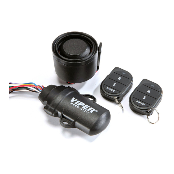
Congratulations Congratulations on the purchase of your state-of-the-art Power Sports Alarm System. Reading this Installer and Owner’s Guide prior to using your system will help maximize the use of its many features. For more information please visit us online (see back cov- er for URL). -
Page 5: Standard Remote Configuration
Standard Remote Configuration Function Button Action Press and release Disarm Press and release Panic Press and hold (any system state) A U X A U X Aux Output Press and release (any system state) Press and release within 5 seconds of arming Tilt bypass system Press and release 2 times within 5 seconds... -
Page 6: Arming
to the system will chirp once, the second two times, and so on, until a total of 4 remotes are learned to the system. Up to 4 remotes can be learned to the system. If you want to learn a 5th remote, the 1st remote will be cleared from the system, and when you learn a 6th remote, the 2nd remote will be cleared, and so on. -
Page 7: Disarming
Tilt/Shock Sensor Trigger Sensitivity for Tilt/Shock sensors are adjustable, see FUNC- TION SELECT MENU 1&2. If the motorcycle is tilted/moved: If the system is in Sleep mode: At first, the siren will • chirp and parking lights will flash 10 times, then the siren will sound continuously for 30 seconds with park- ing light flashes. -
Page 8: Aux
times to indicate the last zone that was triggered when the system was armed. Table of Zones Parking Light Flash System Triggered Zone 4 times Tilt/Shock sensor triggered 5 times Instant triggered 6 times Loop wire triggered 7 times Ignition triggered Press and release . -
Page 9: Anti Motorcycle-Jacking
second, and the parking lights will flash for 10 seconds. Press to stop panic. Anti Motorcycle-Jacking A U X With the ignition ON, press and hold for 2 seconds. The LED will flash quickly indicating that motorcycle-jacking mode is activated. The siren will chirp once every 3 seconds. After chirping 5 times, the siren will chirp once every 1.5 second. -
Page 10: Pin Number Setting
Pin Number Setting Factory Preset Pin Number: 1 (Led Blinks One Time) In disarming mode, turn ignition ON/OFF 8 times within 15 sec- ond, and end in ON position on the eighth time. The LED will stay solid for 2 seconds, then the system enters into PIN setting mode: Confirm the original (preset) PIN Number Turn the ignition OFF within 10 second, LED will start blink- ing slowly to confirm the preset PIN Number. -
Page 11: Memory Function
Enter Valet Mode Turn the ignition ON and then OFF 2 times, and press and hold within 5 seconds. The siren will chirp once, and the system will enter valet mode. In valet mode, the LED will stay on solid for 1 hour, and then will shut off to reduce current draw. - Page 12 After unit has entered the proper feature number you want to change, press the button toggle through the options. The siren chirps according to its current setting. Turn the ignition OFF to exit feature settings. The siren will emit one long chirp. A U X Inside the menu setting, if without any operation within 10 seconds, the siren will emit one long chirp and exit feature...
- Page 13 © 2017 Directed. All rights reserved.
-
Page 14: Power Saving (Sleep) Mode
Power Saving (Sleep) Mode • After 24 hours in the armed status, the LED will flash at a slower rate at once every 4 seconds, and after 48 hours, it will flash once every 8 seconds. • After 96 hours of no activity (arm or alarm trigger) the alarm enters sleep mode. -
Page 15: System Maintenance
System Maintenance This system needs no specific maintenance beyond remote control battery replacement. The remote is powered by one 3V CR2032 battery. Battery Replacement Using a small slotted (flat-head) screwdriver, insert into the slot located along the edge of the remote control and care- fully pry the unit open. -
Page 16: Installation Guide
Installation Guide Fuse Blue (-) Trigger Input White 18AWG Lamp Out White/Brown Lamp In Fuse Red (+) LED Red 22AWG (+) 12V Black (-) LED Violet/White #22 Loop In Black 22AWG (-) Ground Violet/White #22 Loop Out Black/White 22AWG Ant Battery Brown 22AWG Siren Red/White (-) AUX Output... - Page 17 Blue (-) Trigger Input This input wire can be used as an instant trigger input for use with optional single zone sensors. Violet/White Closed Loop This wire can be used to protect a part of the vehicle where a trig- ger is desired when the wires of the connection are not in contact, rather than in contact.
- Page 18 White Parking Light This wire should be connected to the parking lights wire in the ve- hicle. It activates when the system is armed/disarmed, and when the alarm is triggered, It can be set for a (-) or (+) output. See the White/Brown parking light input wire for setting light flash polarity.
- Page 19 Black/White Antenna This wire is the antenna for the control module to receive com- mands from the transmitter. Do NOT cut this wire. Note: The antenna wire should not be bundled with the other har- ness wires as this will reduce the effective range of the transmitter. Keep the antenna wire as straight and horizontal as possible.
-
Page 20: Government Regulations
Government Regulations This device complies with Part 15 of FCC rules. Operation is subject to the following two conditions: (1) This device may not cause harmful interference, and (2) This device must accept any interference received, including interference that may cause undesirable operation. This equipment has been tested and found to comply with the limits for a Class B digital device, pursuant to Part 15 of the FCC Rules. - Page 21 This device complies with the Industry Canada Radio Standards Specification RSS 210. Its use is authorized only on a no-interference, no-protection basis; in other words, this device must not be used if it is determined that it causes harmful interference to services authorized by IC.
-
Page 22: Limited Lifetime Consumer Warranty
Limited Lifetime Consumer Warranty Directed Electronics. (“Directed”) promises to the original purchaser to repair or replace (at Directed’s election) with a comparable reconditioned model any Directed unit (hereafter the “unit”), excluding without limitation the siren, the remote transmitters, the associated sensors and accessories, which proves to be defective in workmanship or material under reasonable use during the lifetime of the vehicle provided the following conditions are met: the unit was purchased from an authorized Directed dealer, the... - Page 23 ASSUME FOR IT ANY DUTY, OBLIGATION OR LIABILITY IN CONNECTION WITH ITS PRODUCTS. DIRECTED DISCLAIMS AND HAS ABSOLUTELY NO LIABILITY FOR ANY AND ALL ACTS OF THIRD PARTIES INCLUDING ITS AUTHORIZED DEALERS OR INSTALLERS. DIRECTED SECURITY SYSTEMS, INCLUDING THIS UNIT, ARE DETERRENTS AGAINST POSSIBLE THEFT. DIRECTED IS NOT OFFERING A GUARANTEE OR INSURANCE AGAINST VANDALISM, DAMAGE OR THEFT OF THE AUTOMOBILE, ITS PARTS OR CONTENTS;...
- Page 24 This warranty is only valid for sale of product(s) within the United States of America and in Canada. Product(s) sold outside of the United States of America or Canada are sold “AS-IS” and shall have NO WARRANTY, express or implied. For further details relating to warranty information of Directed products, please visit the support section of Directed’s website at: www.directed.com.
Need help?
Do you have a question about the 3121V and is the answer not in the manual?
Questions and answers