Sign In
Upload
Download
Table of Contents
Contents
Add to my manuals
Delete from my manuals
Share
URL of this page:
HTML Link:
Bookmark this page
Add
Manual will be automatically added to "My Manuals"
Print this page
×
Bookmark added
×
Added to my manuals
Manuals
Brands
minrray Manuals
IP Camera
UV510A-10-ST
User manual
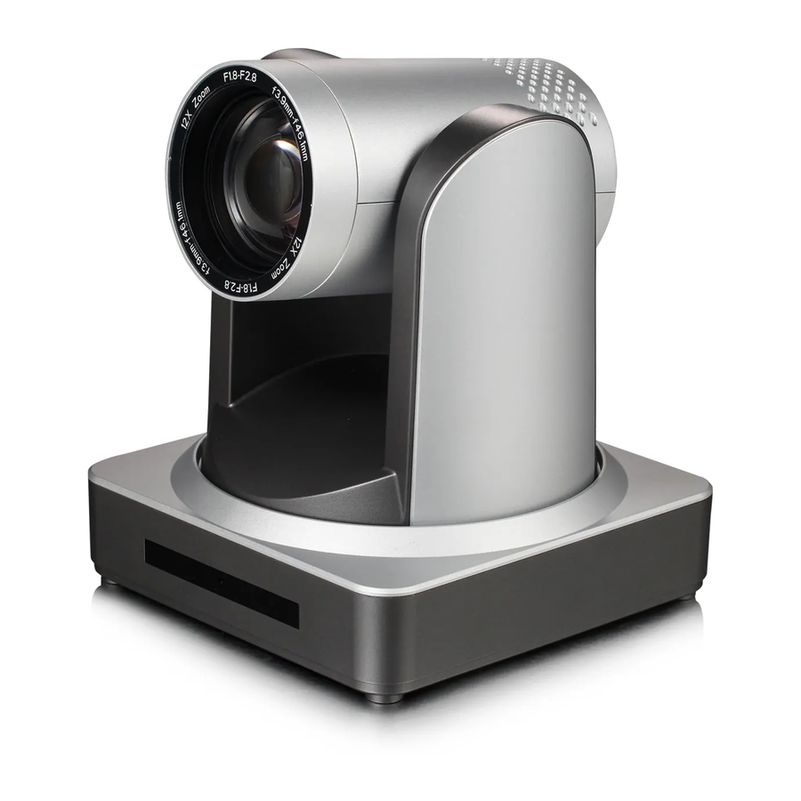
minrray UV510A-10-ST User Manual
Hd color video camera. st series;u3 series;u2 series;hd baset series
Hide thumbs
1
2
Table Of Contents
3
4
5
6
7
8
9
10
11
12
13
14
15
16
17
18
19
20
21
22
23
24
25
26
27
28
29
30
31
32
33
34
35
36
37
38
39
40
41
42
page
of
42
Go
/
42
Contents
Table of Contents
Troubleshooting
Bookmarks
Table of Contents
Table of Contents
1 Fast Installation
Power-On Initial Configuration
Video Output
Camera Interface Explanation
2 Product Overview
Product Introduction
Product Model
Dimension
Accessory
Main Features
Camera Performance
Network Performance
Technical Specification
Interface Instruction
External Interface
Bottom Dial Switch
RS-232 Interface
3 Application Instruction
Video Output
Power-On Initial Configuration
Remote Controller
Applications
Menu Setting
Main Menu
System Setting
Camera Setting
P/T/Z
Video Format
Version
Restore Default
4 Network Connection
Connecting Mode
IE Log in
Web Client
Preview
Playback
Configuration
Video Configuration
Network Configuration
System Configuration
Logout
Wireless Network
5 Serial Communication Control
VISCA Protocol List
Camera Return Command
Camera Control Command
Inquiry Command
Pelco-D Protocol Command List
Pelco-P Protocol Command List
6 Camera Maintenance and Troubleshooting
Camera Maintenance
Troubleshooting
Advertisement
Quick Links
1
Network Performance
2
Remote Controller
3
Network Connection
4
Connecting Mode
5
Network Configuration
Download this manual
HD Color Video Camera
User Manual
Table of
Contents
Previous
Page
Next
Page
1
2
3
4
5
Advertisement
Table of Contents
Need help?
Do you have a question about the UV510A-10-ST and is the answer not in the manual?
Ask a question
Questions and answers
Related Manuals for minrray UV510A-10-ST
IP Camera minrray UV910 User Manual
Ha color video camera (39 pages)
IP Camera minrray UV910 User Manual
(40 pages)
IP Camera minrray uv83 User Manual
Video conference camera (29 pages)
IP Camera Minrray UV850 User Manual
Minrray uv850 hd color video conference camera (21 pages)
IP Camera Minrray UV820 User Manual
Hd color video camera (21 pages)
IP Camera Minrray UV-J1220 User Manual
Integrated hd zoom camera (13 pages)
IP Camera minrray UV830 User Manual
Usb 3.0 hd color video camera (27 pages)
IP Camera minrray UV950A User Manual
Hd color video camera (34 pages)
IP Camera minrray UV950 User Manual
Hd color video conference camera (26 pages)
IP Camera minrray UV510A-20-ST User Manual
Hd color video camera. st series;u3 series;u2 series;hd baset series (42 pages)
IP Camera minrray UV510A-12-U2 User Manual
Hd color video camera. st series;u3 series;u2 series;hd baset series (42 pages)
IP Camera minrray UV510A-20-U2 User Manual
Hd color video camera. st series;u3 series;u2 series;hd baset series (42 pages)
This manual is also suitable for:
Uv510a-05-st
Uv510a-20-st
Uv510a-12-st
Uv510a-05-u2
Uv510a-10-u2
Uv510a-12-u2
...
Show all
Uv510a-20-u2
Uv510a-05-u3
Uv510a-12-u3
Uv510a-10-u3
Uv510a-05-hd
Uv510a-20-u3
Uv510a-12-hd
Uv510a-10-hd
Uv510a-20-hd
Table of Contents
Save PDF
Print
Rename the bookmark
Delete bookmark?
Delete from my manuals?
Login
Sign In
OR
Sign in with Facebook
Sign in with Google
Upload manual
Upload from disk
Upload from URL


Need help?
Do you have a question about the UV510A-10-ST and is the answer not in the manual?
Questions and answers