Table of Contents

Related Manuals for Conair EP2 series


Summary of Contents for Conair EP2 series
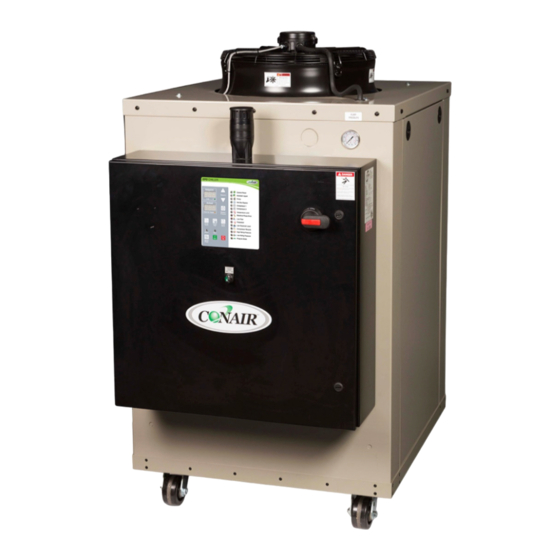
- Page 1 USER GUIDE www.conairgroup.com UGH041-0718 EP2 Series Portable Chillers Portable and Remote Condenser Chillers 4 to 43 Tons Corporate Office: 724.584.5500 Instant Access 24/7 (Parts and Service): 800.458.1960 Parts and Service: 814.437.6861...
- Page 2 Serial Number(s): Model Number(s) DISCLAIMER: Conair shall not be liable for errors contained in this User Guide or for incidental, consequential damages in connection with the furnishing, performance or use of this information. Conair makes no warranty of any kind with regard to this information, including, but not limited to the implied warranties of merchantability and fitness for a particular purpose.
-
Page 3: Table Of Contents
Table of Contents Foreword ..........................................1 Safety Guidelines ........................................1 Pre-Installation ........................................2 Receiving Inspection ....................................... 2 Unit Storage ........................................3 Installation - Chiller ......................................3 Foundation .......................................... 3 Unit Location ........................................3 Rigging ..........................................3 Chilled Process Fluid Piping ..................................3 Figure 1 –... - Page 4 Table 13 - SPI Parameters ..................................18 Modbus RTU (Optional) ....................................18 Table 14 – Standard Controller Modbus RTU Option Parameters..................18 Optional PLC Operation ....................................20 System Initialization....................................... 20 Figure 8 – Start-Up Splash Screen ..............................20 Home - System Overview .................................... 20 Figure 9 –...
- Page 5 Once a Month ........................................32 Every Three Months ....................................... 32 Preventive Maintenance Checklist ................................33 General Troubleshooting ....................................34 Drawings..........................................35...
- Page 6 Page Intentionally Blank...
-
Page 7: Foreword
Foreword Safety Guidelines The portable chiller is a packaged unit that typically Observe all safety precautions during installation, includes a refrigeration circuit, coolant reservoir, and start-up, and service of this equipment. The pumping system in a cabinet. The purpose is to following is a list of symbols used in this manual and provide cooling water or coolant. -
Page 8: Pre-Installation
Pre-Installation Only qualified personnel should install, start-up, and service this equipment. When working on this equipment, observe precautions in this manual as Receiving Inspection well as tags, stickers, and labels on the equipment. When the unit arrives, verify the information on the unit nameplate agrees with the order WARNING: Any use or misuse of this equipment acknowledgement and shipping papers. -
Page 9: Unit Storage
Unit Storage condensation adds a substantial heat load to the chiller. When storing the unit it is important to protect it from damage. Blow out any water from the unit; The importance of properly sized piping cannot be cover it to keep dirt and debris from accumulating or overemphasized. -
Page 10: Installation - Remote Condenser
refrigerant pressure. Allowing the condenser to plug locating piping or conduit over the unit to ensure up from contaminants in the condenser water easy access with an overhead crane or lift to lift out stream adversely affects performance. In order to heavier components during replacement or service. -
Page 11: Interconnecting Refrigerant Piping
top flanges of both legs. Attached the center legs the system. This prevents the formation of toxic using the hardware provide at the center-divider gases, corrosive acids, and scale. panel location. Replace the bolts removed from the side panels to secure the leg assembly to the bottom CAUTION: Do not use soft solders. -
Page 12: Determining Equivalent Line Length
Figure 3 – Condenser Located at Chiller Level the same pressure loss. See the ASHRAE Refrigeration Handbook for more information. Follow these steps when calculating line size: 1. Start with an initial approximation of equivalent length by assuming that the equivalent length of pipe is 1.5 times the actual pipe length. -
Page 13: Table 2 – Liquid Line Sizes For R410A
valve at the condenser to facilitate measuring effect on sub-cooling. In these situations, insulate pressure for service. the liquid lines. Liquid lines do not typically require insulation. However, if exposing the lines to solar heat gain or temperatures exceeding 110 °F, there is a negative Table 2 –... - Page 14 Table 2 – Liquid Line Sizes for R410A (continued) 20 Ton Circuit (R410A) Liquid Line Size (Inch OD) 25 Ton Circuit (R410A) Liquid Line Size (Inch OD) Up Flow (Feet of Run) Up Flow (Feet of Run) Equivalent Horizontal or Equivalent Horizontal or Length (Ft)
-
Page 15: Discharge (Hot Gas) Line Sizing
Table 2 – Liquid Line Sizes for R410A (continued) no trapping of oil in the piping. The chiller is equipped with hot-gas bypass capacity control and 40 Ton Circuit (R410A) Liquid Line Size (Inch OD) the gas in the upflow discharge lines may have Up Flow (Feet of Run) Equivalent Horizontal or... -
Page 16: Table 3 - Horizontal Or Downflow Discharge Line Sizes For R410A (Inches Od)
Table 3 - Horizontal or Downflow Discharge Line Sizes for R410A (inches OD) Total Equivalent Length (Ft) Circuit Tons 1 1/8 1 1/8 1 1/8 1 1/8 1 1/8 1 1/8 1 1/8 1 1/8 1 1/8 1 1/8 1 1/8 1 1/8 1 1/8 1 3/8... -
Page 17: Calculating Refrigerant And Oil Charge
Calculating Refrigerant and Oil Charge Oil level should be checked after the chiller has run for 15 minutes. To determine the approximate charge, first refer to Table 12 and establish the required charge for the Setting Condenser Fan Controls condenser and chiller. Then refer to Table 13 to determine the charge required for the field-installed Depending on the number of condenser fans piping per circuit. -
Page 18: Installation - Electrical
Installation - Electrical leads that are from the unit contactors or the motor terminals. All wiring must comply with local codes and the WARNING: This equipment contains hazardous National Electric Code. Minimum circuit amps (MCA) voltages that can cause severe injury or death. and other unit electrical data are on the unit nameplate. -
Page 19: Standard Controller Operation
Standard Controller Operation The chiller includes a controller to perform all control functions directly from the front panel. When Control Power is applied, the controller initiates a diagnostic test of each indicating light and display segments by briefly lighting each sequentially. As part of this initial diagnostic test, the program revision level displays for a moment. -
Page 20: Table 9 - Temperature Displays
Table 8 – Operating Buttons (continued) Button Description of Operation Pump Test With the chiller stopped, pressing this button briefly engages the pump to test its operation. The pump will not run if there are any active alarms. The pump shuts down by either pressing the Stop button or pressing the Pump Test button a second time. -
Page 21: Program Menu
Table 10 – Operating Lights (continued) Light Description of Operation Compressor #2 The Compressor #2 light is solid green when Compressor #2 is running, flashes red if a compressor overload or fault occurs, and is solid red if the controller is attempting to start the compressor before the anti-recycle timer has timed out. Compressor #2 is enabled when the temperature of the coolant leaving the chiller rises above the Set Point by an amount equal to the control parameter PS2 (Compressor #2 Positive Spread). -
Page 22: Table 11 - Controller Program Menu
in the Set Point display until the desired value shows. Alarm Silence/Reset button and Stop button Press the Start button to enter the new value. Press simultaneously for 10 consecutive seconds until the Stop button to cancel and revert to the previous “PRG”... -
Page 23: Spi Communications (Optional)
Table 12 – Controller Control Fault Logic Component Shut-Off Required Resets Fault Alarm Indication Pump Compressor Panel Sensor Low Reservoir Level Reservoir Level Light flashes red Temperature Limit Safety Set Point and Process Displays Flash, Temperature Limit Light flashes red Temperature Limit Warning Temperature Limit Light flashes yellow Pump Motor Overload... -
Page 24: Modbus Rtu (Optional)
Table 13 - SPI Parameters Command Poll Select Description Echo This is the controller integrity command used to accept and retain data and provide it 20 20 20 21 in response to a poll inquiry. This is an open 4-byte ASCII format with ASCII units. Version This is the controller version command used to provide a version number following 20 22... - Page 25 Table 14 – Standard Controller Modbus RTU Option Parameters (continued) Register Description Read/Write Format Notes 4011 Low Alarm Delay Integer 4012 High Alarm Delay Integer 4013 Temperature Display Units Integer 0 = °F, 1 = °C 4015 Brownout Enabled Integer 0 = Disabled, 1 = Enabled 4024 Remote Setpoint Enabled...
-
Page 26: Optional Plc Operation
Optional PLC Operation the options present. For assistance with this process please contact the Customer Service Department and have the unit Serial Number ready for reference As an option on fixed-speed compressor chillers so they can pull up the details of your unit. (standard on units with the variable-speed compressor option), there is a Programmable Logic System Initialization... -
Page 27: Home - Full Screen
When power is applied, you will see the main screen Figure 10 – Full Screen similar to the above. From the main screen, you can navigate to other screes and menus, each of which may have several sub-screens or menus depending on your chiller’s configuration. -
Page 28: Menu 1 - Alarms Active
Menu 1 - Alarms Active Menu 1 – Circuit Details Screen When a critical system fault occurs, the controller To access the Circuit Details Screen (Figure 14) use activates the HMI alarm handler (Figure 12). This Menu 1 (Figure 11) or touch the option Details on forces the alarm screen to appear and will display the Home Screen (Figure 9). -
Page 29: Menu 2 - Overview
Menu 2 – Default Touching the I-LOCK 2 button opens the next Interlocks Screen (Figure 16). CAUTION: The Defaults screen provides the ability to Figure 16 – Interlocks 2 Screen restore the control system back to factory defaults in the case that an unknown setting modification occurred and the system now behaves unexpectedly. -
Page 30: Menu 2 - Trending
Menu 2 – Trending The trending screen (Figure 20) displays the setpoint temperature, process temperature, expansion valve, and optional hot gas bypass valve (if present) resisters for easy analysis of the system operation. Trending is always enabled and always running. Figure 20 –... -
Page 31: Modbus Rtu (Optional)
Modbus RTU (Optional) As an option, the PLC controller is available with a Modbus output on the PLC. The Modbus default set up uses a Baud Rate of 57,600, Data Length of 8 bits, Odd Parity, and Stop Bit of 1, Com Port 1. Table 16 –... - Page 32 Table 16 – PLC Controller Modbus RTU Parameters (continued) Modbus Register Data Format Data Access Level Description 30003 WORD Read SYSTEM ALARMS/WARNINGS BOOL Bit 0 Read Return Water High BOOL Bit 1 Read Return Water High High BOOL Bit 2 Read Suction Pressure Sensor Alarm BOOL...
- Page 33 Table 16 – PLC Controller Modbus RTU Parameters (continued) Modbus Register Data Format Data Access Level Description 30005 WORD Read PLC INPUT STATUS BOOL Bit 0 Read PLC Input 0 BOOL Bit 1 Read PLC Input 1 BOOL Bit 2 Read PLC Input 2 BOOL...
-
Page 34: Start-Up
Table 16 – PLC Controller Modbus RTU Parameters (continued) Modbus Register Data Format Data Access Level Description 32008 INTEGER Read Suction Temperature 32009 INTEGER Read Discharge Temperature 32010 INTEGER Read Suction Pressure 32011 INTEGER Read Discharge Pressure 32012 INTEGER Read Compressor 1 Anti-Cycle Time 32013 INTEGER... -
Page 35: Step 1 - Connect Main Power
Step 1 - Connect Main Power Unwanted Side Effects of Improper Water Quality Corrosion Connect main power properly ensuring it matches • Scale the voltage shown on the nameplate of the unit. • Fouling Check the electrical phase sequence prior to start- •... -
Page 36: Step 3 - Check Condenser
Step 3 - Check Condenser Table 17 – Fill Water Chemistry Requirements There are three possible types of condenser present Water Characteristic Quality Limitation in the chiller: Integral air-cooled, water-cooled, or Alkalinity (HCO 70-300 ppm remote air-cooled. It is important to verify the chiller Aluminum (Al) Less than 0.2 ppm will have adequate condenser cooling for proper... -
Page 37: Step 6 - Turn On Control Power
protect against a possible freeze-up if no glycol is in compressor may cycle on and off causing swings in the coolant. Once the proper glycol solution is temperature. present, adjust the Freezstat to the appropriate Note: For chillers with the variable-speed compressor option operating under low load conditions with the compressor speed at setting. -
Page 38: Preventive Maintenance
Preventive Maintenance 6. Check the refrigerant sight glass for air bubbles or moisture indication. If the sight glass indicates that there is a refrigeration problem, have the Once your portable chiller is in service, follow the unit serviced as soon as possible. maintenance procedures shown below as closely as possible. -
Page 39: Preventive Maintenance Checklist
Preventive Maintenance Checklist Week Number Maintenance Activity Date Clean Air Coils and Inlet Filters Temperature Control Pump Discharge Pressure Coolant Level Glycol Concentration Pump Seal Refrigerant Sight Glass Electrical Connections Incoming Voltage Compressor #1 L1 Amps Compressor #1 L2 Amps Compressor #1 L3 Amps Compressor #2 L1 Amps Compressor #2 L2 Amps... -
Page 40: General Troubleshooting
General Troubleshooting Problem Possible Cause Remedy Compressor will not Compressor overload Check supply voltage, amperage of each leg, contactor start and wiring, and overload set point Compressor contactor Replace if faulty Compressor failure Contact Customer Service for assistance Pump will not start Pump overload Check supply voltage, amperage of each leg, contactor and wiring, and overload set point... -
Page 41: Drawings
General Troubleshooting (continued) Problem Possible Cause Remedy Insufficient cooling Process load too high Check to make sure chiller is properly sized for process (temperature continues load to rise above set point) Coolant flow through evaporator too high or low Adjust flow to proper level Insufficient condenser cooling See “High Refrigerant Pressure”... - Page 42 Notes...
- Page 43 We’re Here to Help Conair has made the largest investment in customer support in the plastics industry. Our service experts are available to help with any problem you might have installing and operating your equipment. Your Conair sales representative also can help analyze the nature of your problem, assuring that it did not result from misapplication or improper use.
- Page 44 Goods Authorization Number (RGA) will be issued by Conair’s Service Department. Returned equipment must be well crated and in proper operating condition, including all parts. Returns must be prepaid. Purchaser must notify Conair in writing of any claim and provide a customer receipt and other evidence that a claim is being made.
Need help?
Do you have a question about the EP2 series and is the answer not in the manual?
Questions and answers
Alarm display compressor recycling while is not yet at the setpoint
The alarm display may be showing because the unit is in a low load condition, causing the "To Process" temperature to drop below the Set Point. This can happen if the Partial Load LED is on for an extended time, indicating unused capacity. If the temperature falls below the Set Point by an amount equal to the control parameter nS2 (default 5 °F for Compressor #2), the unit may enter an alarm state. Additionally, if there is an active fault such as High Refrigerant Pressure, Pump Overload, or another issue requiring a manual reset, the alarm will remain until the fault is cleared and reset.
This answer is automatically generated