Table of Contents
Advertisement
Installation
Operation
Maintenance
Troubleshooting
Instant Access
Parts and Service
(800) 458-1960
(814) 437-6861
www.conairnet.com
Portable Chillers
Series 1 Water-Cooled (W1) and
Air-Cooled (A1) Models with PLC Control
The Conair Group, Inc.
One Conair Drive
Pittsburgh, PA 15202
Phone: (412) 312-6000
Fax: (412) 312-6227
UGH017/0500
Advertisement
Chapters
Table of Contents

Related Manuals for Conair W1-1.5


Summary of Contents for Conair W1-1.5
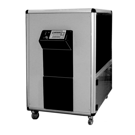
- Page 1 Portable Chillers Series 1 Water-Cooled (W1) and Air-Cooled (A1) Models with PLC Control Installation Operation Maintenance Troubleshooting The Conair Group, Inc. Instant Access One Conair Drive Parts and Service Pittsburgh, PA 15202 (800) 458-1960 Phone: (412) 312-6000 (814) 437-6861 Fax: (412) 312-6227 www.conairnet.com...
- Page 2 Volts Phase Cycle DISCLAIMER: The Conair Group, Inc., shall not be liable for errors contained in this User Guide or for incidental, consequential dam- ages in connection with the furnishing, performance or use of this information. Conair makes no warranty of any kind with regard to this information, including, but not limited to the implied warranties of merchantability and fitness for a particular purpose.
-
Page 3: Table Of Contents
....1-1 NTRODUCTION ABLE OF Purpose of the User Guide ......1-2 ONTENTS How the Guide is Organized . - Page 4 ....5-1 AINTENANCE ABLE OF Maintenance Features ......5-2 Warnings and Cautions .
-
Page 5: Introduction
NTRODUCTION q q Purpose of the User Guide ..1-2 q q How the Guide is Organized . . .1-2 q q Your responsibilities as a user .1-2 q q ATTENTION: Read this so no one gets hurt ...1-3 Series 1 Portable Chillers, PLC Control UGH017/0500... -
Page 6: Purpose Of The User Guide
This User Guide describes Conair’s Series 1 Water-cooled and URPOSE OF Air-cooled Portable Chillers and explains step-by-step how to install, operate, maintain and repair this equipment. Before installing this product, please take a few moments to UIDE read the User Guide and review the diagrams and safety infor- mation in the instruction packet. -
Page 7: Attention: Read This So No One Gets Hurt
We design equipment with the user’s safety in mind. You can ATTENTION: avoid the potential hazards identified on this machine by fol- lowing the procedures outlined below and elsewhere in the EAD THIS SO NO User Guide. ONE GETS HURT WARNING: Improper installation, oper- ation, or servicing may result in equip- ment damage or personal injury. -
Page 9: Description
ESCRIPTION q q What is the Portable Chiller? . . .2-2 q q Typical Applications ..2-3 q q Limitations ....2-3 q q How it Works: Water-cooled Portable Chiller . -
Page 10: What Is The Portable Chiller
The Conair Series 1 Portable Chillers provide self-contained HAT IS THE sources of chilled water and are available in either water- or air-cooled models. Ranging in size from 1.5 Hp to 13 Hp in ORTABLE the air-cooled configuration and 1.5 Hp to 15 Hp in the water- cooled design [approximate capacities of 1.5 tons of refrigera-... -
Page 11: Typical Applications
The Conair A1 and W1 Portable Chillers can be used any- YPICAL where a reliable source of process cooling water - with stable temperature control - is required. PPLICATIONS These portable chillers are available for cooling injection molding, blow molding, thermoforming, extrusion, air com- pressors, metal plating, anodizing, degreasing, heatset/web offset printing presses, and dryer after-coolers. -
Page 12: How It Works Water Cooled Portable Chiller
Process circulation OW IT ORKS ATER COOLED ORTABLE HILLER Hot fluid from the process enters the chiller through the From Process valve into the pump reservoir. Fluid is chilled in the Pump draws water evaporator and exits from pump reservoir through the To Process and moves it through the valve and tube, returning to... - Page 13 Refrigerant circulation OW IT ORKS ATER COOLED ’ The liquid refrigerant CONT The high pressure vapor travels from leaves the accumula- the compressor through the coiled tor, passing through the condenser (where it is condensed into a thermal expansion valve, liquid) and is stored in the accumulator.
-
Page 14: How It Works: Air-Cooled Portable Chiller
Process circulation OW IT ORKS COOLED ORTABLE HILLER Hot fluid from the process enters the chiller through the From Process valve into the pump reservoir. Pump draws fluid Fluid is chilled in the from pump reservoir evaporator and exits and moves it through the through the To Process strainer and flow switch to valve and tube, returning to... - Page 15 Refrigerant circulation OW IT ORKS COOLED ’ CONT The liquid refrigerant The high pressure vapor leaves the accumulator, travels from the compressor passing through the ther- through the condenser (where mal expansion valve, fans cool vapor into a liquid) where it expands and and liquid is stored in the cools.
-
Page 16: Portable Chiller Features
View fluid level on water level gauge Options include: q 60 Hz process pump with: 1 1/2 Hp for W1-1.5, W1-2 2 Hp for W1-3, W1-4 3 Hp for W1-5, W1-7.5, W1-10, W1-15 q To Process and From Process valves... - Page 17 Air-cooled Models ORTABLE HILLER EATURES Condenser Fans compresses the refrigerant circulate air across the con- from a high pressure vapor denser to cool refrigerant into a high pressure liquid. Compressor compresses the refriger- Hot Gas Bypass valve ant from a low pressure vapor into a high pres- balances the load on the sure vapor.
-
Page 18: Specifications
(+-) 5% based on compressor manufacturer’s ratings and are subject to change without notice. ‡ Based on 50° F (10 °C) water temperature leaving the chiller and 60 °F (16 °C) water temperature returning to the chiller (except W1-1.5 which has 55 °F (13 °C) water temperature returning to the chiller). - Page 19 Air-cooled Models PECIFICATIONS front side back 10.5 {267} 5.5 {140} 10 {254} 9 {229} MODEL A1-1.5 A1-2.25 A1-3.25 A1-4 A1-5 A1-7.5 A1-10 A1-13 Performance characteristics Capacity ✝ , tons 1.18 1.79 2.77 3.62 4.27 6.06 8.75 10.95 Compressor Hp {kW} 1.5 {1.1} 2.25 {1.7} 3.25 {2.4}...
-
Page 20: Pump Curves
URVES 60 HZ PUMP PERFORMANCE CURVES Flow Rate (gpm) 50 HZ PUMP PERFORMANCE CURVES Flow Rate (gpm) 2-12 ESCRIPTION Series 1 Portable Chillers, PLC Control UGH017/0500... -
Page 21: Installation
NSTALLATION q q Unpacking the Boxes ..3-2 q q Warnings and Cautions ..3-3 q q Preparing for Installation ..3-4 q q Making Process Plumbing Connections . -
Page 22: Unpacking The Boxes
The portable chiller comes fully assembled in a single crate. NPACKING THE CAUTION: Lifting OXES The Series 1 Portable Chillers are designed to easily roll on casters. If, for some reason you need to lift the chiller, take all precautions to avoid personal injury or damage to the chiller. -
Page 23: Warnings And Cautions
WARNING: Improper installation, oper- ARNINGS AND ation, or servicing may result in equip- ment damage or personal injury. AUTIONS This equipment should only be installed, adjust- ed, and serviced by qualified technical person- nel who are familiar with the construction, oper- ation, and potential hazards of this type of machine. -
Page 24: Preparing For Installation
Plan the location for the chiller and prepare the area properly. REPARING FOR Position the Chiller as close to the process machine as possi- NSTALLATION ble. Place the chiller in position near the process machine so that fluid lines can be connected from the process machine to the chiller and back. -
Page 25: Making Process Plumbing Connections
Warm fluid from process equipment enters the chiller at the AKING From Process connection and chilled fluid returns to the process equipment through the To Process connection. ROCESS Remove the shipping plastic pipe plug from LUMBING the female connections on the back of the portable chiller. ONNECTIONS Make sure the male pipe threads are clean and new. -
Page 26: Filling The Chiller
The Chiller is shipped without coolant. The chiller is filled ILLING THE manually during installation. Use water as the coolant down to 40 °F (4 °C). Below 40 °F and down to 20 °F (-7 °C), use an HILLER ethylene glycol or propylene glycol solution. To fill with water: Attach water hose to Fill/Drain valve. - Page 27 ILLING THE HILLER ’ CONT ° Temperature of Process Fluid Close the To Process and From Process valves. Open the Fill/Drain valve and fill chiller to the fill mark on the Water Level gauge. If the chiller is overfilled, the excess fluid spills out the vent tube. DO NOT OVERFILL.
-
Page 28: Checking Refrigerant Charge
Under low load conditions, when the hot-gas bypass valves are operating, bubbles may be visible in the sight glass. This is normal. If the charge is low contact Conair service or have a local, cer- tified refrigeration technician add refrigerant to the system. WARNING: Refrigerant hazard... -
Page 29: Connecting The Main Power Source
WARNING: Improper installation, oper- ONNECTING ation, or servicing may result in equip- ment damage or personal injury. This equipment should only be installed, adjust- ed, and serviced by qualified technical person- OWER OURCE nel who are familiar with the construction, oper- ation, and potential hazards of this type of machine. -
Page 30: Checking Electrical Connections
Turn on main power source. NITIALLY The control boots up and the screen displays the Portable Chiller model number. TARTING THE Conair Chiller HILLER A1 - 5 WARNING: Initial startup Do not press any buttons after initially applying power to the Chiller. Let the Chiller set, undis- turbed, for a minimum of 8 hours before starting the Chiller. - Page 31 After the initial 8-hour minimum warmup, continue with start- NITIALLY TARTING THE Press the Next arrow on the control to move to the Main screen. HILLER ’ CONT The Main screen displays: STATUS SETUP RUN ALM Press the Run arrow. STATUS SETUP RUN ALM press arrow...
-
Page 32: Checking For Leaks
Before placing the Chiller into operation you need to check HECKING FOR for fluid leaks. Do this by turning on the pump from the con- trol and letting it run while you check inside the chiller. EAKS From the main screen: Press the Run arrow on the screen. -
Page 33: Connecting The Remote Control
If your chiller has the optional remote interface, you need to ONNECTING connect it to the chiller control. The chiller control panel is hinged on the bottom. Pull down on the top of the outer bezel of the control to expose the internal wiring. Plug the interface cable from the remote controller into the communication cable EMOTE connection. -
Page 35: Operation
PERATION q q PLC Control Features ..4-2 q q Before Starting ....4-3 q q Powering Up ....4-4 q q Running/Stopping the Chiller . -
Page 36: Plc Control Features
PLC C ONTROL EATURES Display screen shows status, setup and run modes Status lights Option arrows Up / Down Scroll arrows show the run status of com- choose parameters dis- scroll through the display pressor, process pump, and played on the screen screens alarm/shutdown Drop-open bezel... -
Page 37: Before Starting
Before you start daily operation of the chiller, you need to EFORE perform scheduled preventative maintenance. Necessary main- tenance is describe in the Maintenance section of this Users TARTING Guide. WARNING: Electrical hazard Be sure that power to the chiller is OFF when doing any maintenance on the chiller. -
Page 38: Powering Up
Turn on the main power. The chiller control automatically performs its bootup rou- tine. the screen displays the Portable Chiller model num- ber along with the Enter command. Conair Chiller A1 - 5 Press the Scroll arrow to move to the Main screen. -
Page 39: Running/Stopping The Chiller
After you have viewed all the Status screens and made any UNNING necessary changes to the Setup screens, you are ready to run the Chiller. To run the Chiller from the main screen: TOPPING Press the Run arrow on the Main screen. HILLER STATUS SETUP RUN ALM... -
Page 40: Viewing Chiller Status
The Status screens are read-only screens. You cannot make IEWING changes to these screens. To view the status screens: HILLER Press the Status arrow on the Main screen. TATUS STATUS SETUP RUN ALM Press arrow Use the scroll arrows to scroll through the status screens. -
Page 41: Q Q Viewing Chiller Status
q Refrigerant suction pressure - shows the status of the IEWING refrigerant suction pressure in PSIG. NOTE: Typical refrigerant suction pressure is between 55 PSIG and 95 HILLER PSIG. TATUS Ref Suction Pressure ’ 70 PSIG CONT q Refrigerant Discharge pressure - View the status of the refrigerant discharge pressure in PSIG. -
Page 42: Programming Settings
The PLC control allows you to program various parameters ROGRAMMING for the Chiller: ETTINGS q Temperature Setpoint The desired To Process fluid temperature. q Auto Tune PID Helps maintain the setpoint temperature without over- shooting. q High Temperature Deviation Set the number of degrees the temperature can rise above the setpoint temperature without an alarm. -
Page 43: Changing Setpoint Temperature
Use the Temperature Setpoint screen to set the desired temper- HANGING ature of the To Process fluid. ETPOINT To display the Setpoint temperature from the Main screen, press the Setup arrow. The Setpoint screen displays: EMPERATURE Setpoint 10 C number flashes The current setpoint temperature displays in both Fahrenheit (F) and Celsius (C). -
Page 44: Resetting Pid Settings
Use the PID reset to return the control to the factory settings. ESETTING To reset PID from the main screen: ETTINGS Press the Setup arrow. STATUS SETUP RUN ALM Press arrow Press the Scroll arrows to scroll through the Setup screens. Stop when you get to the PID Reset screen. -
Page 45: Changing High Temperature Deviation
Decide how many degrees above the setpoint temperature you HANGING want the chiller to deviate before an alarm occurs. EMPERATURE To set the high temperature deviation: EVIATION Press the Setup arrow. STATUS SETUP RUN ALM press arrow Continue to press the arrow to scroll through the Setup screens. -
Page 46: Setting Percent Glycol
To set the percent ethylene glycol or propylene glycol solution ETTING determine the desired temperature of the process fluid leaving the chiller. ERCENT Use water as the coolant for a setpoint temperature of the LYCOL process fluid down to 40 °F (4 °C). Below 40 °F and down to 20 °F (-7 °C), a glycol solution is required. - Page 47 ETTING Press the Up/Down Scroll arrows to scroll through the setup screens. ERCENT LYCOL ’ CONT Stop when you get to the Percent Glycol screen: number % E.G. BY VOL flashes Low Temp Cutout The screen displays the percent of glycol by volume cur- rently used.
-
Page 48: Setting Fan Setpoints
For the Air-cooled Chillers you can choose the pressure, in ETTING pounds per square inch, at which the fans cycle. To set the Fan Setpoints from the main screen: ETPOINTS Press the Setup arrow. STATUS SETUP RUN ALM Press arrow Press the Scroll arrows to scroll through the Setup screens. - Page 49 ETTING Press Enter to save the change. ETPOINTS ’ CONT Press the scroll arrows to move to Fan 2. Repeat the steps for changing Fan 2 setpoint tempera- tures. Press the Escape/Previous Screen button to return to the main screen. 4-15 UGH017/0500 Series 1 Portable Chillers, PLC Control...
-
Page 50: Setting Auto Tune Mode
Use the Auto Tune Mode to maintain good temperature con- ETTING trol and minimize overshooting the setpoint temperature. To display the Auto Tune Mode from the main screen: Press the Setup arrow. STATUS SETUP RUN ALM Press arrow This screen is password pro- tected. - Page 51 ETTING Press the Scroll arrows to scroll to the Tune screen. ’ CONT TUNE Press arrow Press the Auto Tune arrow. The control begins tuning. This takes about 15 seconds. When tuning, the screen displays ‘TUNE Tuning’ mes- sage. When tuning is complete, the screen displays ‘TUNE Normal’...
-
Page 52: Manually Starting/Stopping The Pump
To run or stop the pump from the main screen: ANUALLY Press the arrow pointing to Run on the screen. TARTING TOPPING THE STATUS SETUP RUN ALM press arrow The first Run screen displays. Use the Scroll arrows to scroll through Run screens to the Manual Pump screen. - Page 53 AINTENANCE q q Maintenance Features ..5-2 q q Warnings and Cautions ..5-3 q q Preventative Maintenance Schedule ....5-4 q q Entering Maintenance Screens .5-6 q q Checking Electrical Connections .
-
Page 54: Maintenance Features
Conair Series 1 Portable Chillers need regular, scheduled AINTENANCE maintenance for peak performance. EATURES To maintain the best performance of the chiller, it must be cleaned and inspected regularly. Maintenance includes a daily, monthly, and semi-annual schedule. Use this maintenance schedule as a guide. You may need to shorten the time of the maintenance schedule, depending on how often you use the chiller. -
Page 55: Warnings And Cautions
Follow all cautions and warnings when working on the equip- ARNINGS AND ment. AUTIONS WARNING: Improper installation, oper- ation, or servicing may result in equip- ment damage or personal injury. This equipment should only be installed, adjust- ed, and serviced by qualified technical person- nel who are familiar with the construction, oper- ation, and potential hazards of this type of machine. -
Page 56: Preventative Maintenance Schedule
q q Daily, or as often as needed REVENTATIVE ❒ ❒ Checking electrical connections Make sure electrical connections are properly seated. AINTENANCE Checking Electrical Connections, in the Maintenance section. CHEDULE ❒ ❒ Checking process fluid level in the pump tank Check the process fluid level in the water level gauge on the back of the chiller. - Page 57 q q Monthly REVENTATIVE ❒ ❒ Inspecting cooling water treatment system If your chiller uses a cooling water treatment system, AINTENANCE maintain proper chemical levels and follow the recom- mendations of your water treatment specialist. Change CHEDULE water in the reservoir tank monthly. ’...
-
Page 58: Entering Maintenance Screens
To enter Maintenance screens requires security clearance. NTERING There are two security levels built into the control let you limit access to the some setup and maintenance screens. The AINTENANCE two security levels are: CREENS q User Allows user to view all Status screens, access the Run screens, and access the Setup screens for: temperature setpoint, high temperature deviation, and PID reset. - Page 59 NTERING Compressor Run Time in hours AINTENANCE CREENS ’ CONT Compressor Cycles in hours Pump Run Time Pump Cycles Hot Gas Bypass Cycles Press the Escape/Previous Screen button to exit the Maintenance screens and return to the main screen. The password stays in effect for 5 minutes after using it;...
-
Page 60: Checking Electrical Connections
WARNING: Electrical hazard HECKING Before performing any work on this item, dis- connect and lock out electrical power sources to LECTRICAL prevent injury from unexpected energization or startup. ONNECTIONS WARNING: Improper installation, oper- ation, or servicing may result in equipment damage or personal injury. This equipment should only be installed, adjust- ed, and serviced by qualified technical person- nel who are familiar with the construction, oper-... -
Page 61: Cleaning The Evaporator Or Water-Cooled Condenser
Minerals and other contaminants produce deposits, scales, LEANING THE slime, or algae on the heat transfer surfaces exposed to water. Fouled surfaces result in decreased cooling capacity. VAPORATOR Implement a water treatment program to slow the fouling. ATER CAUTION: Hot Surfaces Always protect yourself from hot surfaces when COOLED working on the Portable Chiller, especially when... -
Page 62: Cleaning The Air-Cooled Condenser
Use a flashlight to check between coil surfaces. Clean the dirty coils with a soft brush. Flush with cool water or a commercial coil cleaner. If your unit has the optional air filter supplied by Conair, clean it using water or air. Replace as needed. 5-10 AINTENANCE... -
Page 63: Checking The Refrigerant Charge
Under low load conditions, when the hot-gas bypass valves are operating, bubbles may be visible in the sight glass. This is normal. If the charge is low contact Conair service or have a local, cer- tified refrigeration technician to add refrigerant to the system. Sight... -
Page 64: Checking Reservoir Level
WARNING: Electrical hazard HECKING Before performing any work on this item, dis- connect and lock out electrical power sources to ESERVOIR prevent injury from unexpected energization or startup. EVEL Check the fluid level in the reservoir. The meniscus in the sight glass on the back of the chiller should be in line with the mark on the sight glass. -
Page 65: Troubleshooting
ROUBLESHOOTING q q Before Beginning ... .6-2 q q A Few Words of Caution ..6-3 q q Identifying the Cause of a Problem ....6-3 q q Answering Alarms . -
Page 66: Before Beginning
You can avoid most problems by following the recommended EFORE installation, operation and maintenance procedures outlined in this User Guide. If you have a problem, this section will help EGINNING you determine the cause and tell you how to fix it. Before you begin troubleshooting: ❒... -
Page 67: A Few Words Of Caution
WARNING: Improper installation, oper- ORDS ation, or servicing may result in equip- ment damage or personal injury. AUTION This equipment should only be installed, adjust- ed, and serviced by qualified technical person- nel who are familiar with the construction, oper- ation, and potential hazards of this type of machine. -
Page 68: Answering Alarms
When an alarm condition occurs, the display flashes the alarm NSWERING condition and the Alarm light on the control panel lights. Press the Alarm Silence/ Reset button to acknowledge the alarm and LARMS silence the optional audible alarm. Press the Alarm arrow on the Main screen: STATUS SETUP RUN ALM press arrow... - Page 69 Use the Alarm table for a description of each alarm: NSWERING LARMS ’ CONT Alarm No. Alarm Description Low Tank Level The fluid level in the pump tank is low. Flow Fault There is low flow of the process fluid at the pump discharge.
-
Page 70: Control Problems
PLC; reconnect or replace as needed. ❐ Check the PLC indicator lights for normal status. Contact Conair Service if sta- tus is not normal. There is a problem with The control panel may have the control panel. -
Page 71: Q Q Control Problems
ONTROL ROBLEMS ’ CONT Possible cause Solution Symptom The input voltage is Check the main supply volt- The control is lit and incorrect age. It must be within 10% of there is no alarm the nameplate rating. condition. The com- pressor hums, but does not run. -
Page 72: Alarm Conditions
LARM ONDITIONS Possible cause Solution Alarm Process fluid level in tank Fill tank to proper level. See ALM 01 is low. Checking Reservoir Level, in Low Water Tank the Maintenance section. Level alarm Inspect for leaks in the process piping. Repair as necessary. Making Plumbing Connections, in the Installation section. -
Page 73: Q Q Alarm Conditions
LARM ONDITIONS ’ CONT Possible cause Solution Alarm The To Process and From Open/adjust valve(s). ALM 02 Process valves are closed. Flow Fault alarm The Process Fluid strain- Clean the strainer. er is clogged. Process fluid level in Fill the reservoir. See Making reservoir is low and float Process Plumbing... - Page 74 Change percent glycol setpoint, if needed. There is a refrigerant Check for oil in chiller cabinet leak. and bubbles in refrigerant sight glass. Consult Conair Service for repair. Checking the Pressure Faulty pressure transduc- Transducer, in the Troubleshooting section.
- Page 75 LARM ONDITIONS ’ CONT Possible cause Solution Alarm Clogged/dirty air-cooled Clean the coil. See Cleaning ALM 04 condenser. the Air-cooled Condenser, High Refrigerant the Maintenance section. Discharge Pressure alarm Blocked air flow to air- Move chiller or unblock air cooled condenser. passageway.
- Page 76 LARM ONDITIONS Possible cause Alarm OLUTION Overload set incorrectly. Check table on wiring diagram ALM 05 for correct full load amperage Compressor draw. Adjust overload accord- Overload alarm ingly. ❏ Check supply voltage. Low supply voltage. Supply voltage to contactor should be +- 10% of name- plate voltage.
- Page 77 LARM ONDITIONS ’ CONT Possible cause Solution Alarm Overload set incorrectly. Check table on wiring diagram ALM 06 for correct full load amperage Pump Overload draw. Adjust overload accord- alarm ingly. ❏ Check supply voltage. Low supply voltage. Supply voltage to contactor should be +- 10% of name- plate voltage.
- Page 78 LARM ONDITIONS ’ CONT Possible cause Solution Alarm The hot gas bypass valve Shut isolation valve to the Hot ALM 07 is not working properly Gas Bypass solenoid. If the To High Temperature (possibly stuck open) Process temperature starts to Safety alarm go down, the solenoid valve is faulty.
- Page 79 LARM ONDITIONS ’ CONT Possible cause Solution Alarm The hot gas bypass valve If the To Process temperature ALM 08 is not working properly starts to go down, the solenoid Low Temperature (possibly stuck closed). valve is faulty. Have a certified Cutout alarm refrigeration technician replace the solenoid valve.
-
Page 80: Checking And Replacing Switches
WARNING: Electrical hazard HECKING AND Before performing any work on this unit, discon- nect and lock out electrical power sources to EPLACING prevent injury from unexpected energization or startup. WITCHES The pump tank has one or two float switches. The float switch (low level cutout) activates the Low Water Level alarm. -
Page 81: Checking The Pressure Transducer
WARNING: Coolant hazard HECKING THE Refrigerant can cause freezing of skin. All prop- er precautions should be taken any time the RESSURE refrigerant system is worked on. Any adjustment that involves the refrigerant should only be per- RANSDUCER formed by a certified refrigeration technician. The transducer produces a 0.5-4.5 VDC analog signal that is read by the PLC, which relates it to a pressure, based on the range of the transducer. -
Page 82: Checking The Temperature Transmitter And Rtd
RANSMITTER The Conair Portable Chiller uses a standard 100 ohm RTD to monitor process temperature. A transmitter is also included and is located in the temperature transmitter electrical box. To check the temperature transmitter and RTD: Always refer to the wiring Disconnect and lockout power to the chiller. - Page 83 HECKING THE EMPERATURE RANSMITTER AND ’ CONT OHMS VOLTS CURRENT Temperature Temperature Temperature transmitter board transmitter board transmitter board black black black Volt Current Power Controller meter sensor meter meter supply Problem Possible cause Solution No reading No power to board. Check voltage at power supply.
-
Page 84: Replacing The Rtd
To replace the RTD: EPLACING THE Disconnect and lockout power to the chiller. Disconnect the To Process tubing from the To Process connection. Fill/Drain valve To Process connection Open the Drain/Fill valve and drain water from the unit so the water level is lower that the RTD. Open the side of the chiller. -
Page 85: Replacing The Temperature Transmitter
To replace the temperature transmitter: EPLACING THE Disconnect and lockout power to the chiller. EMPERATURE Open the side of the chiller. RANSMITTER Disconnect the RTD wiring from the transmitter electrical box. Refer to the wiring diagram. Disconnect transmitter wiring from main electrical panel. -
Page 86: Removing Pump Components
The pump’s wet end (impeller, motor, and seal assembly) can EMOVING be removed for service. Disconnect and lockout power to the chiller. OMPONENTS Open the drain/fill valve and drain the water from the chiller. Open this Fill/Drain valve side Open the side of the chiller. Remove the bolts connecting the pump assembly to the pump housing. -
Page 87: Replacing Overload Modules
WARNING: Electrical hazard EPLACING Before performing any work on this unit, discon- nect and lock out electrical power sources to VERLOAD prevent injury from unexpected energization or startup. ODULES Normally if the overload trips, resetting the overload and cor- recting the cause is typically all that is needed. However, if the overload continues to trip, it may be necessary to replace the overload module. -
Page 88: Replacing Fuses
WARNING: Electrical hazard EPLACING Before performing any work on this unit, discon- nect and lock out electrical power sources to USES prevent injury from unexpected energization or startup. To replace fuses: Disconnect and lockout power to the chiller. Open the electrical enclosure and locate the fuses. -
Page 89: Replacing The Contactor
WARNING: Electrical hazard EPLACING THE Before performing any work on this unit, discon- nect and lock out electrical power sources to ONTACTOR prevent injury from unexpected energization or startup. To replace contactor for the pump or compressor: Disconnect and lockout power to the chiller. Open the electrical enclosure and locate Always refer to the wiring the correct contactor. -
Page 90: Replacing The Plc
Before performing any work on this unit, discon- nect and lock out electrical power sources to prevent injury from unexpected energization or startup. NOTE: Contact your Conair Service representative before replacing the PLC. Disconnect and lockout power to the chiller. Open the top electrical enclosure. -
Page 91: Appendix
Conair has made the largest investment in customer support in ’ the plastics industry. Our service experts are available to help with any problem you might have installing and operating your equipment. Your Conair sales representative also can help analyze the nature of your problem, assuring that it did not result from misapplication or improper use. - Page 92 Returns must be prepaid. Purchaser must notify Conair in writing of any claim and provide a customer receipt and other evidence that a claim is being made.
-
Page 93: Maintenance Log
AINTENANCE Reading Date Maintenance Item Compressor Amps, 100% loaded Discharge Pressure Suction pressure Evaporator water out temperature Process Water Pressure, In/Out Condenser Water Temperature, In/Out Condenser Water Pressure, In/Out Condenser Fan Amps (1) Condenser Fan Amps (2) Pump Amps Unit Volts Primary Secondary Condenser Air Temp In... - Page 95 Evaporator and Piping RESSURE Pressure Drops ABLES A1/W1-7.5 A1/W1-2 A1/W1-3 A1/W1-10, A1-13 A1/W1-1.5 A1/W1-4 A1/W1-5 W1-15 Flow Rate, GPM UGH017/0500 Series 1 Portable Chillers, PLC Control PPENDIX...
-
Page 96: Pressure Tables
Condenser and Piping RESSURE Pressure Drops ABLES W1-1.5 W1-2 W1-3 W1-7.5 W1-5 W1-4 W1-10 W1-15 Flow Rate, GPM Series 1 Portable Chillers, PLC Control UGH017/0500 PPENDIX... - Page 97 SCOT MOTORPUMP™ J56 & JM FRAME STRAIGHT CENTRIFUGAL 304 STAINLESS STEEL l l INSTALLATION l l OPERATION l l MAINTENANCE INCLUDES MECHANICAL SEAL REPLACEMENT Check pump for shortage and damage immediately upon Use the next larger pump size for suction arrival.
- Page 98 Temperature — Total temperature, not the rise, is the OPERATION measure of safe operation for a motor. If temperature by Pre-Start — Before initial start of the pump, check as thermometer exceeds limits for insulation class, follows: investigate and change operating conditions. The rotation must be checked upon installation.
- Page 99 5. Hold shaft against rotation as described in paragraph 8 of disassembly procedure, and thread impeller on shaft until it is tight against the shaft shoulder. The impeller will compress the seal spring to the proper length assuring correct pressure on lapped faces.
- Page 100 8. Remove impeller from shaft, being careful 5. Position the cover so that the convex side is not to lose the impeller key, spring and facing you and install on cast iron motor gasket. If impeller is difficult to remove, it disc.
Need help?
Do you have a question about the W1-1.5 and is the answer not in the manual?
Questions and answers