Advertisement
Quick Links
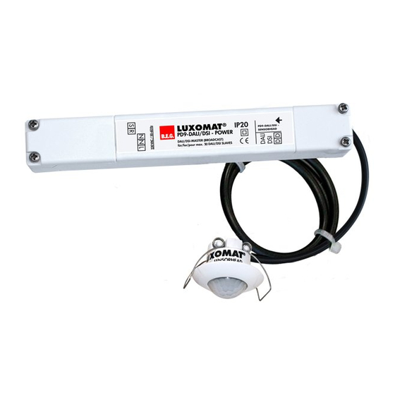
LUXOMAT
Installation and Operating Instruction for B.E.G. - Occupancy detectors PD9-M-DALI/DSI-FC und PD9-M-DALI/DSI-GH-FC
1a. Features
* For connection of up to 50 lamps
* Suitable for dimmable electronic
ballasts and control modules
* DALI/DSI output
* Constant light control
* Manual switching/dimming
* Semi or completely automatic
operation
* Luminance (brightness) set point,
switch-off delay time for LIGHT and
orientation-light adjustable
* Sensor and power sections in one
housing
* Infrared remote control
Option:
Wall bracket for remote control
IR-PD-DALI
6. Exclude sources of
interference
PD9-FC
PD9-GH-FC
In case the sensing area of the
LUXOMAT
PD9-M-DALI/DSI(-GH) is
®
too large or areas are being covered
that should not be monitored, the range
can be reduced or limited through use
of the enclosed masking clips.
®
1b. Mounting preparations
Work on the 230 V mains supply
may only be carried out by quali-
fied professionals or by instructed
persons under the direction and
supervision of qualified skilled elec-
trical personnel in accordance with
electrotechnical regulations.
Disconnect supply before installing!
When in Master / Slave mode of
operation, the Master-appliance
must always be installed at the
location where there is least
daylight.
4. Settings by remote control when open
DSI/
DALI
Resetting when
open: Deletes
or
all values set
with the remote
control, light
OFF.
+
or
1
to
min
max
ON
OFF
1
to
min
50
1500
Lux
Lux
max
t < 5 sec.
ON
OFF
50
1500
Lux
Lux
7. Dimensions
max
PD9-M-DALI/DSI
PD9-M-DALI/DSI-GH
ON
25
OFF
45
165 mm
PD9-M-DALI/DSI(-GH)
2a. Installation LUXOMAT
PD9-M-
®
DALI/DSI(-GH)-FC
The detector has
min. 34 mm
22 - 30 mm
been designed and
developed specifi-
cally for installation in
suspended ceilings.
A circular opening of
diameter min. 34 mm
must be produced in
the ceiling.
Having connected the cables in accordance with the
regulations, connect the power supply via the RJ11
plug. Therefore, open the power supply with the help
of the screws and close it afterwards. After that, put
the power supply through the opening in the ceiling
and mount the sensor onto the ceiling according to
figure.
Unlocking device – Activation of
the programming mode
Switching between DSI and
DALI program
Dimming of the lighting on the
desired luminance value
Automatic reading in the
current light value as new
luminance set point
50
Adjusting of the luminance set point
1500
–
Lux
Lux
+ / – small steps
+
–
/
big steps
50
1500
max
Lux
Lux
30
Follow-up time light
min
ON
Orientation lighting on/off
OFF
max
Orientation lighting and its
10
min
follow-up time
ON
Preset/user mode
OFF
=> (see page 2, point 10)
Fully automatic /semi automatic
mode => (see page 2, point 9)
Locking device – Exit program-
ming mode
LED flashes
Permanent protection against
sabotage
25
45
24 mm
24 mm
2b. Self test cycle
The LUXOMAT
PD9-M-
®
DALI/DSI(-GH) enters an
initial 60-second self-test
cycle, when the supply is
first connected. The oc-
cupancy detector is ready
for operation.
5. Key functions in closed state
Lock device
Test mode
Reset to deactivate
Resetting when closed
The lighting relay is switched off, i.e. opened and the
follow-up times reset.
Permanent protection against sabotage
This function blocks the unit permanently (green LED is illumi-
nated). This operating mode can only be activated during the
t < 5 sec.
period of 5 seconds after pressing the "lock" button. This status
will only permit actuating the function "Light on/Light off".
The procedure for leaving this mode is as follows:
1. Switch off the current
2. Apply current for 31 – 59 seconds
3. Switch of the current again
50
1500
4. Apply current
Lux
Lux
5. Open detector
Light on/off when closed
=> (see page 2, point 9)
The light will remain switched on/off for as long as movements
are detected in the areas of coverage. Once the last movement
has been detected, the light will remain on for the duration of
the follow-up time as per setting.
The appliance will then return independently to the mode
selected (Fully or Semi-automatic).
8. Range of Coverage
PD9-M-DALI/DSI
quer zum Melder gehen
Walking across
2.50 m
frontal zum Melder gehen
Walking towards
Unterkriechschutz
Seated
2
3
1
PD9-M-DALI/DSI-GH
Overview range in dependence from the mounting
height
Mounting
Range (circular detection) T=18°C
height
walking across
5.00 m
Ø=3.00 m
6.00 m
Ø=3.50 m
7.00 m
Ø=4.20 m
8.00 m
Ø=4.80 m
9.00 m
Ø=5.40 m
10.00 m
Ø=6.00 m
GB
3. Settings carried
out using remote
control (optional)
Remote control LUXOMAT
®
IR-PD-DALI
Check Battery:
Open battery compartment
by pressing the plastic
springs together and remo-
ving the battery-holder.
RJ
9.00 m
Advertisement

Related Manuals for B.E.G. LUXOMAT PD9-M-DALI/DSI-FC


Summary of Contents for B.E.G. LUXOMAT PD9-M-DALI/DSI-FC
- Page 1 PD9-M-DALI/DSI(-GH) LUXOMAT ® Installation and Operating Instruction for B.E.G. - Occupancy detectors PD9-M-DALI/DSI-FC und PD9-M-DALI/DSI-GH-FC 1a. Features 1b. Mounting preparations 2a. Installation LUXOMAT PD9-M- 2b. Self test cycle 3. Settings carried ® DALI/DSI(-GH)-FC out using remote control (optional) Work on the 230 V mains supply...
- Page 2 9. Fully / Semi automatic mode 13. Wiring diagram 15. Technical data PD9-M-DALI/DSI(-GH) (for IR-PD-DALI functions see page 1) Standard mode with master DALI occupancy detectors Power supply: 230 V~ ±10 % Power consumption: < 1W Fully automatic operation Ambient temperature: -25°C to +50°C In this operating mode, the lighting switches automati- ...
Need help?
Do you have a question about the PD9-M-DALI/DSI-FC and is the answer not in the manual?
Questions and answers