Advertisement
Quick Links
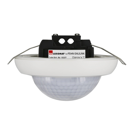
LUXOMAT
Montage-Anleitung
DE
Vorbereitung
Arbeiten an elektrischen Anlagen
!
dürfen nur von Elektrofachkräf
ten oder von unterwiesenen
Personen unter Leitung und
Aufsicht einer Elektrofachkraft
entsprechend den elektrotech
nischen Regeln vorge nommen
werden.
Vor Montage Leitung
!
spannungsfrei schalten!
DALI ist nicht SELV – Es gelten die
!
Installationsvorschriften für
Niederspannung.
Die DALISchraubklemmen dürfen
!
nicht an 230 VAC angeschlossen
werden!
Funktionsweise
Besonders flacher, adressierbarer
DALI-Multisensor mit integriertem
DALI-Applikations-Controller.
Das Gerät wird ausschließlich über
den DALI-Bus mit Betriebsspannung
versorgt. Bewegen sich Menschen,
Tiere oder sonstige Wärmequellen im
Erfassungsbereich, schaltet das Gerät
vollautomatisch DALI-Leuchten ein.
Wird keine Bewegung mehr erkannt,
wird das Licht nach 10 Minuten wieder
ausgeschaltet. Zur Vergrößerung
des Erfassungsbereiches können alle
B.E.G. Multisensoren mit der Kennung
„DALILINK" in der Produktbezeichnung
eingesetzt werden. Voller Funktions-
umfang mit Zubehör aktivierbar.
Montage
Fig. 1
Fig. 2
Fig. 1: Federklemme abschrauben,
wenn UP- oder AP-Montage
erwünscht ist.
Fig. 2: DALI-Drähte werden mit
kleinem Schlitzschraubendreher
angeschlossen.
Fig. 3a: Gerät wird in Zwischendecke
eingeführt.
Fig. 3b: Gerät wird an UP-Dose
befestigt.
Fig. 3c: Gerät wird auf AP-Adapter
befestigt.
Beim Aufsetzen der Abdeckung
!
(d) muss der Lichtsensor 1 frei
bleiben.
Fig. 4: Abdecklamellen (e) zur Einschrän-
kung des Erfassungsbereiches.
Fig. 5: Lichtsensor 1 für Punkt-Licht-
messung, Lichtsensor 2 für
Umgebungslichtmessung.
net PD4N-DALILINK Enr 1301100/93377
®
Mounting-Instructions
EN
Preparations
Work on the mains supply may
!
only be carried out by qualified
professionals or by instructed
persons under the direction and
supervision of qualified skilled
electrical personnel in accord
ance with electrotechnical
regulations.
Disconnect supply before
!
installing!
DALI is not SELV – the installa
!
tion instructions for low voltage
apply
The DALI screw clamps must not
!
be connected to 230 VAC!
Operation
Especially flat, addressable DALI
multisensor with integrated DALI
application controller.
The device is supplied with operating
voltage via the DALI bus. If humans,
animals or other sources of heat move
in the area of detection, the device
automatically switches on DALI lamps.
If no movement is detected, the light
is switched off again after 10 minutes.
To increase the detection range, all
B.E.G. Multisensors with the identifier
„DALILINK" in the product description
can be used. The complete functional
range can only be activated using
accessory.
Mounting
Fig. 3a
68 mm
!
DALI
Fig. 1: Unscrew the spring clamp if
flush-mounting or surface-
mounting is desired.
Fig. 2: DALI wires are connected with a
small slotted screwdriver.
Fig. 3a: Device is inserted into false
ceiling.
Fig. 3b: The device is attached to a
flush-mounted box.
Fig. 3c: Device is mounted on SM
adapter.
When replacing the cover, please
!
take care that the opening for
light sensor 1 is placed on the
same.
Fig. 4: Blinds (e) are clipped to restrict
detection area.
Fig. 5: Light sensor 1 for point light
measurement, light sensor 2 for
ambient light measurement.
Montage - Instructions
FR
Preparation du montage
Travailler sur le réseau électrique
!
ne s'improvise pas, seul un
electricien qualifié et habilité
doit effectuer ce raccordement.
Avant de commencer
!
l'installation, assurezvous que
l'alimentation est coupée.
DALI est différent de SELV – Les
!
prescriptions d'installation pour
basse tension doivent être
respectées.
Les bornes DALI ne doivent pas
!
être raccordées à 230 VCA!
Fonctionnement
Multicapteur DALI adressable extra-
plat, avec contrôleur d'application
DALI incorporé.
Ce multicapteur est alimenté uni-
quement par le bus DALI. En cas de
mouvements d'une personne, d'un
animal ou d'autres sources de chaleur, le
multicapteur allume automatiquement
les luminaires DALI. Ils seront éteints
au bout de 10 minutes s'il n'y a plus
de mouvements. Pour élargir la zone
de détection, il est possible d'utiliser
d'autres multicapteurs de la gamme
« DALILINK ». L'activation de toutes fonc-
tions n'est possible qu'avec accessoire.
Montage
Fig. 3b
Fig. 3c
93307
d
!
e
e
Fig. 1: Dévisser la pince à ressort si
un montage encastré ou en
applique est souhaité.
Fig. 2: Les cables DALI sont a raccorder
à l'aide d'un petit tournevis plat.
Fig. 3a: Insertion dans un faux plafond
Fig. 3b: L'appareil est fixé à la boîte
d'encastrement.
Fig. 3c: L'appareil est monté sur
l'adaptateur AP.
En remplaçant le couvercle,
!
veuillez respecter que l'ouverture
pour le capteur de lumière 1 est
placée sur ce capteur.
Fig. 4: Mise en place des obturateurs (e)
pour limiter la zone de détection.
Fig. 5: Capteur de lumière 1 pour la
mesure de la lumière ponctuelle,
capteur de lumière 2 pour la
mesure de la lumière ambiante.
Montering-Instruktioner
SV
Förberedelser
Arbete och inkoppling får endast
!
utföras av behörig elektriker.
Bryt alltid strömmen innan
!
montering och installation!
DALI är inte SELV se gällande
!
installations anvisningar för
lågspänning
DALI får inte anslutas till
!
nätspänning
Funktion
Adresserbar multisensor med
integrerade DALI funktioner.
Enheten strömförsörjs via DALI-bussen
och kräver 2mA. Vid detekterad rörelse
så tänder detektorn belysningen och
släcker 10 minuter efter sista detek-
terade rörelsen. Detekteringsområdet
kan utökas med hjälp av flera sensorer.
Montering
Fig. 4
e
Light
Fig. 5
sensor 2
d
!
Light
e
sensor 1
Fig. 1: Skruva av fjädrarna för
utanpåliggande eller infällt
montage.
Fig. 2: Daliledningar ansluts med en
liten rak skruvmejsel.
Fig. 3a: Montage i undertak
Fig. 3b: Montage i dosa
Fig. 3c: Utanpåliggande montage
Vid montering av kåpan, se till att
!
hålet för ljussensor 1 placeras
rätt!
Fig. 4: Avskärmningslameller för att
begränsa detekteringsytan.
Fig. 5: Ljussensor 1 spotmätning,
ljussensor 2 mäter omgivande
ljus.
Advertisement

Related Manuals for B.E.G. LUXOMAT PD4N-DALILINK


Summary of Contents for B.E.G. LUXOMAT PD4N-DALILINK
- Page 1 PD4N-DALILINK Enr 1301100/93377 LUXOMAT ® Montage-Anleitung Mounting-Instructions Montage - Instructions Montering-Instruktioner Vorbereitung Preparations Preparation du montage Förberedelser Arbeiten an elektrischen Anlagen Arbete och inkoppling får endast Work on the mains supply may Travailler sur le réseau électrique dürfen nur von Elektrofachkräf...
- Page 2 Indicateurs de LED-Funktions anzeigen LED function indicators fonctionnement à LEDs LED indikering • Kurz an: • Shortly on: • Allumées (brièvement): • Kort till: A Grün A Green A Verte Bewegung Movement Mouvements A Grön rörelse slav (Slave-Betrieb) (Slave mode) (Mode esclave) B Röd rörelse...
- Page 3 Schaltbilder Wiring diagrams Schémas de câblage Kopplingsschema Schematische Schaltbilder – Bitte Schematic diagrams – when Schémas de raccordement de base – Kopplingsschema – Vid anslutning av beachten Sie beim Anschließen die connecting the detector, please veuillez respecter le marquage des bornes detektorn, var uppmärksam på...
- Page 4 IR-PD-KNX-Mini 93307 – AP Montageset IP54 B.E.G. LUXOMAT ® SM mounting kit IP54 92112 – Kit de montage AP IP54 Ram för utanpåliggande montage IP54 IR-PD-DALI-Mini Rutab AB (HK Sverige) • Lerbacksgatan 2 • 571 38 Nässjö • Växel: 0380 - 55 50 50 • Fax: 0380 - 12303 • mail@rutab.se • www.rutab.se...
Need help?
Do you have a question about the PD4N-DALILINK and is the answer not in the manual?
Questions and answers