Panasonic FV-15NLFS1 Installation And Operating Instructions Manual
In-line fan
Hide thumbs
Also See for FV-15NLFS1:
- Service manual (8 pages) ,
- Service manual (7 pages) ,
- Service manual (6 pages)
Table of Contents
Advertisement
READ AND SAVE THESE INSTRUCTIONS
Thank you for purchasing this Panasonic product.
Please read these instructions carefully before attempting to install, operate or service the
Panasonic product. Please carefully read the "GENERAL SAFETY INFORMATION" (P.2 ~ 4) of
this manual before use. Failure to comply with instructions could result in personal injury or
property damage. Please explain to users how to operate and maintain the product after
Please retain this booklet for future reference.
Installation and Operating Instructions
CONTENTS
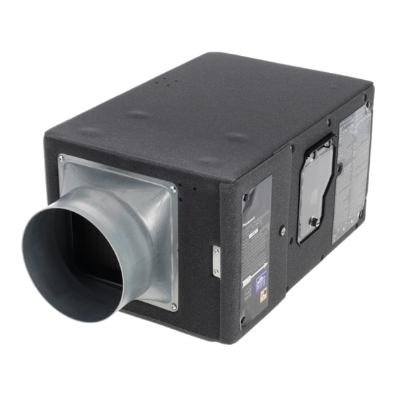
In-Line Fan
FV-15NLFS1
Model No.
2 ~ 4
4
4
5
5
6 ~ 8
9 ~ 10
10 ~ 11
11
12
12
Advertisement
Table of Contents

Related Manuals for Panasonic FV-15NLFS1


Summary of Contents for Panasonic FV-15NLFS1
-
Page 1: Table Of Contents
Please read these instructions carefully before attempting to install, operate or service the Panasonic product. Please carefully read the “GENERAL SAFETY INFORMATION” (P.2 ~ 4) of this manual before use. Failure to comply with instructions could result in personal injury or property damage. -
Page 2: General Safety Information
GENERAL SAFETY INFORMATION For Your Safety To reduce the risk of injury, loss of life, electric shock, fire, malfunction, and damage to equipment or property, always observe the following safety precautions. Explanation of symbol word panels The following symbol word panels are used to classify and describe the level of hazard, injury, and property damage caused when the denotation is disregarded and improper use is performed. - Page 3 GENERAL SAFETY INFORMATION Sufficient air is needed for proper combustion and exhausting of gases through the flue (chimney) of fuel burning equipment to prevent backdrafting. Follow the heating equipment manufacturer’s guideline and safety standards such as those published by the National Fire Protection Association (NFPA), and the American Society for Heating Refrigeration and Air Conditioning Engineers (ASHRAE) and the local code authorities.
-
Page 4: Description
GENERAL SAFETY INFORMATION NOTICE Do not install the product where ducts are configured as shown below. Adaptor Excessive bending Successive bending Squeezed duct Bend close to duct adaptor Please install the tube cover or similar items at the air inlet, otherwise it may cause the entry of foreign matter or rain, affecting product performance. -
Page 5: Supplied Accessories
SUPPLIED ACCESSORIES Appearance Part name Quantity Hanger Screw (M4X8) Installation and operating instructions Limited warranty DIMENSIONS Unit : inch (mm) 23 3/8 (594 ) 15 3/4 (399) 3 3/4 (97) 8 3/4 (223) flow Part name Part name Pre-filter Damper Sub-efficient filter Power cord Main PCB... -
Page 6: Installation
INSTALLATION Before installing please choose the installation direction. You can install the product with maintenance board towards down or towards side. (Fig.1, Fig.2) If there are joists on ceiling, you should install it with the maintenance board towards down, otherwise you may can not to maintain filter. Maintenance board towards side Maintenance board towards down (Not applicable for ceiling with joists) - Page 7 INSTALLATION 4.Install Φ6 inch ducts. Interior duct Mastic or approved foil (1) Connect the circular duct (suggest using tape the insulated flexible duct) to adaptor by Exterior duct mastic or approved foil tape. Place/wrap insulation around duct and/or fan in order to minimize possible condensation buildup within the duct.
-
Page 8: Installation
INSTALLATION 1-2 Install with the maintenance board towards side Note Hanger (Fix by 4 screws) This method can not applicable for ceiling with joists. Hanger (Fix 1. Fix the hangers (3 pcs) on fan body by screws. by 3 screws) (Fig.8) 2.Install hanger bolts on ceiling, and put washers Hanger (Fix by... -
Page 9: Operation
(Fig.12) Main switch Port receptacle for add-on Module provides additional features. (Module sold separately) For details, please consult Panasonic Call Center Control panel Telephone : 1-866-292-7299 (USA) 1-800-669-5165 (Canada) Fig.12 Running indicator When the indicator is on green, indicates the product is running. -
Page 10: Maintenance
OPERATION Temperature dial switch Adjusting the temperature protection value of the product by this dial switch, you can choose 15 °F ~ 40 °F (stepless) or turned to OFF position. Default setting : 15 °F If the product inside temperature detected by sensor is lower than setting value, the fan will stop for 60 minutes, then according to the detected value to determine whether to operate. -
Page 11: Practical Guide To Installation
Note Please replace sub-efficient filter by Panasonic Model FV-FL0815NL1 or FV-FL1315NL1. If you do not use the Panasonic filter will result in poor Fig.15 performance. 4.Install back the filters and close the maintenance board by twist hand screw. Please make sure that the arrow direction on sub–efficient filter is same... -
Page 12: Specifications
The unit should be serviced by qualified technicians only. Your product is designed and manufactured to ensure a minimum of maintenance. Should your unit require service or parts, call Panasonic Call Center at 1-866-292-7299 (USA) or 1-800-669-5165 (Canada). Two Riverfront Plaza, Newark, NJ 07102 5770 Ambler Drive, Mississauga, Ontario L4W 2T3 www.panasonic.com...
Need help?
Do you have a question about the FV-15NLFS1 and is the answer not in the manual?
Questions and answers