Table of Contents
Advertisement
Quick Links
Advertisement
Table of Contents

Related Manuals for PP Systems TARGAS-1


Summary of Contents for PP Systems TARGAS-1
- Page 1 TARGAS-1 Portable Photosynthesis System Operation Manual Version 1.02 2018 PP Systems. All Rights Reserved February 2018 PP Systems 110 Haverhill Road, Suite 301 Amesbury, MA 01913 U.S.A. Tel: +1 978-834-0505 Fax: +1 978-834-0545 Email: support@ppsystems.com URL: www.ppsystems.com...
-
Page 2: Table Of Contents
Leaf Gas Exchange Measurements – Recommended Set-up ..............26 When should I record a measurement? ....................26 Schematic of TARGAS-1 Portable Photosynthesis System Air Supply System ........27 Routine System Checks Before Starting ..................... 28 TARGAS-1 Operation Manual V. 1.02... - Page 3 Drierite .............................. 35 Foam Filters ............................36 Absorber Filters ..........................36 “O” Rings ............................36 TARGAS-1 Menu Overview (Flow Chart) ....................37 Splash Screen ............................. 37 General Screen Info ............................ 39 Measure Screen Info ..........................39 Parameters in Parenthesis ........................39 Heartbeat and Display Update Rate: .......................
- Page 4 Averaging Setting ..........................59 Interval Settings ..........................59 TARGAS ID Setting .......................... 60 Settings 3 Menu ............................60 Probe Port Settings ........................... 61 Ref On Time Setting ......................... 62 An On Time Setting .......................... 62 TARGAS-1 Operation Manual V. 1.02 support@ppsystems.com...
- Page 5 Ship Mode Settings ........................... 67 Processes..............................69 SRC (Soil Respiration Chamber) Process ....................69 Connecting the SRC-2 Soil Respiration Chamber to the TARGAS-1 ..........69 SRC – Start Process (Step 1) ......................70 SRC – Volume and Area Settings (Step 2) ..................70 SRC –...
- Page 6 Injection – Injection Phase (Step 6) ....................101 Information Menu ............................102 About ..............................103 Contact ..............................103 Calibration ..............................104 Calibration ............................104 Connecting Calibration Gas to the TARGAS-1 ................105 O Calibration ............................107 TARGAS-1 Operation Manual V. 1.02 support@ppsystems.com...
- Page 7 Connecting Dew Point Generator to the TARGAS-1 ..............108 Touch Calibration ..........................110 PAR ............................... 110 Light Unit Calibration ..........................112 Diagnostics ..............................114 CO2 IRGA Diagnostics .......................... 115 H2O IRGA Diagnostics .......................... 116 Battery Diagnostics ..........................117 CO2 Zeros Diagnostics ......................... 117 H2O Zeros Diagnostics .........................
- Page 8 Checking for Leaks Associated with the PLC5 ................148 PLC5 Gas Connector ........................149 PAR Sensor ............................ 149 Light Unit ............................149 Appendix 1. Photosynthesis Equations Used in TARGAS-1 ..............150 Mass Flow ............................150 Transpiration ........................... 150 Leaf Temperature ........................... 151 Saturation Vapor Pressure ......................
-
Page 9: Welcome
This manual and the information contained within are copyrighted to PP Systems. No part of the manual may be copied, stored, transmitted or reproduced in any way or by any means including, but not limited to, photocopying, photography, magnetic or other mechanical or electronic means, without the prior written consent of PP Systems, Inc. -
Page 10: User Registration
PP Systems or an authorized agent for repair or replacement of the defective part(s). Prior to returning equipment to PP Systems for service, you must first get in contact with our Service Manager (service@ppsystems.com) to request a case number for reference and tracking purposes. -
Page 11: Unpacking And Storage Of Your Equipment
Powering up the TARGAS-1 for the First Time When you first receive your new TARGAS-1 from PP Systems you will need to first connect it up to the external power supply/charger prior to powering up the instrument. To avoid accidental power up during shipment we put the instrument into “Ship Mode”... -
Page 12: Data Storage
Data Storage For convenience and ease it is very important to note that all TARGAS-1 system data is recorded and saved directly to a USB flash drive (i.e. memory stick or thumb drive). A USB flash drive is included in the spares kit (Part No. -
Page 13: Plc5 Leaf Cuvette
• PP Systems is a registered trademark of PP Systems, Inc. • PP Systems is continuously updating its products and reserves the right to amend product specifications without notice. • All brand names are trademarks or registered trademarks of their respective owners. -
Page 14: Light Unit (Optional)
PP Systems as well as for use with commercially available sensors for environmental monitoring applications (PAR, soil temperature, etc.). The IRGAs form the core of the TARGAS-1 Portable Photosynthesis System for measurement of both and H O. Non-dispersive infra-red (NDIR) refers to the transmission of a broad-band infra-red wavelength from the IRGA source lamps. - Page 15 O and CO molecules have diverse absorption spectra, so we use two prominent absorption peaks, seen below at 2.60 and 4.26 µm, respectively. The TARGAS-1 electronics could be considered the fifth component, which processes raw analog-to-digital (A/D) information from the IRGAs detectors, accurately translating this information into gas concentrations.
-
Page 16: System Components For Measurement Of Leaf Gas Exchange
The TARGAS-1 IRGAs are quite stable owing to their construction, calibration and thermal environment, but various circumstances can cause apparent changes over time. Some changes may require recalibration, although one of the strengths of TARGAS-1 is that recalibration is not a routine (annual) maintenance task. The factory calibration ranges of 0-2000 µmol mol and 0-75 mb water vapor are ideally suited for most typical applications. -
Page 17: Plc5 Leaf Cuvette
The following sensors/chambers are external to the TARGAS-1 and electrical connection is made to the Probe Ports (Probe 1 and/or Probe 2) located on the back of the TARGAS-1. See Probe Port Settings on page 61 for more information for proper connection. Gas connections are made to the “Gas In” and “Gas Out”... -
Page 18: Trp-3 Temperature/Par Probe
We recommend recalibration of the quantum sensor every 2 years. TRP-3 Temperature/PAR Probe An optional probe can be used with the TARGAS-1 for measurement of temperature and PAR. It consists of a rugged, aluminum housing with black foam cover. It also includes a standard tripod thread mount for use with commercially available tripods. -
Page 19: Cpy-5 Canopy Assimilation Chamber
PAR within the chamber. There are two gas connections required, one to the GAS IN port and the other to the GAS OUT port on the TARGAS-1. This sensor can be used on Probe Port 1 or 2. -
Page 20: Getting Familiar With The Targas-1 Portable Photosynthesis System
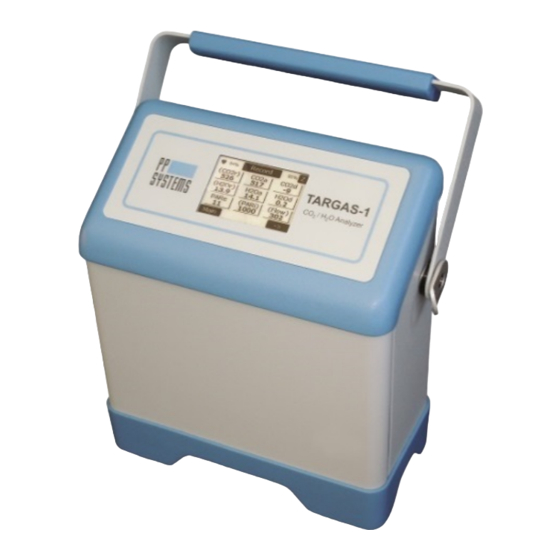
• Range: 0-50 • Accuracy: ± 0.3 C at 25 The soil temperature sensor should not require recalibration. Getting Familiar with the TARGAS-1 Portable Photosynthesis System TARGAS-1 Portable CO O Gas Analyzer (Main Console) TARGAS-1 Operation Manual V. 1.02 support@ppsystems.com... - Page 21 Adjustable Carry Handle scrubber status Flashing Heart and manual (Power Status) Zero button and battery capacity Touch display Shoulder strap fixture (one on each side of console) Polyurethane shock-absorbing base and battery compartment TARGAS-1 Operation Manual V. 1.02 support@ppsystems.com...
-
Page 22: Back Of Targas-1
An air filter is included with each system and we recommend fitting it to the AIR IN port to keep dirt and dust from entering the analyzer. See External Air Filter on page 140 for more information. TARGAS-1 Operation Manual V. 1.02 support@ppsystems.com... -
Page 23: Plc5 Leaf Cuvette
PLC5 Leaf Cuvette The PLC5 Leaf Cuvette is designed to work with the TARGAS-1 Portable CO O Analyzer for measurement of leaf gas exchange on a wide variety of plants including broad leaves, narrow leaves, grasses and small needle conifers. -
Page 24: Quick Start
TARGAS-1 set-up and to ensure that the system is performing perfectly before starting a measurement campaign. 1. Connect the PLC5 Leaf Cuvette gas and signal connectors to the TARGAS-1 console as shown below and close the cuvette head. Electrical Connection Gas Connection 2. - Page 25 3. Connect the sampling tubing to the AIR IN port on the back of the TARGAS-1 console. Remember to make sure the external air filter is fitted to the AIR IN port (see External Air Filter on page 140). This will be your reference air. We strongly recommend that your reference air is as...
-
Page 26: Leaf Gas Exchange Measurements - Recommended Set-Up
This can be achieved by using a homemade buffer volume (i.e. 20 liter bucket, large water container, etc.) or using the air supply intake unit provided by PP Systems. The air supply intake unit draws ambient air from about 2.3 meters above the ground and should help to smooth the reference air allowing for rapid and accurate measurement of leaf gas exchange. -
Page 27: Schematic Of Targas-1 Portable Photosynthesis System Air Supply System
Schematic of TARGAS-1 Portable Photosynthesis System Air Supply System Air in Air Supply Intake Unit TARGAS-1 CO O Gas Analyzer PLC5 Leaf Air Control System AIR IN Cuvette Filter Absorber Smoothing Control Volume Absorber Control REF OUT Pump PLC Air Out... -
Page 28: Routine System Checks Before Starting
USB Memory port on the TARGAS-1 console for data storage. If you do not have this you will be unable to save data and it will have to be recorded manually. -
Page 29: System Power
System Power The TARGAS-1 has an internal, rechargeable lithium ion battery pack capable of providing continuous power to the instrument for up to 10 hours. The TARGAS-1 is supplied with an external AC power adapter to charge and/or power the TARGAS-1. -
Page 30: Targas-1 Main Console Components
Power Switch The power switch is located in the upper left hand corner of the back panel. To power on the TARGAS-1 simply push in the switch. When power is on the illumination ring around the switch will turn blue. To turn off, simply press the switch again bringing it back to the flush position. -
Page 31: Ext Power Jack
If the TARGAS-1 was put into ship mode, it will not power on until external power is applied. To bring the TARGAS-1 out of ship mode, first connect external power to the instrument, and then turn it on by pressing the “ON/OFF” button. See Ship Mode Settings on page 67 for more information. -
Page 32: Gas Ports
Gas Ports There are 4 gas ports on the TARGAS-1. Each port is designed for use with 1/8” (.125”) ID tubing or a mating quick disconnect. • GAS OUT: Exhaust air from the IRGAs • GAS IN: Reference air entering the IRGAs (when PLC5 is used) or sample air when in absolute or closed modes •... -
Page 33: Absorber Columns
See Zero Settings on page 55. Important Note It is critical that the Molecular Sieve is fresh to ensure that the TARGAS-1 receives a good zero for long term calibration and stability of the CO and H O gas analyzers. -
Page 34: Molecular Sieve Repackaging
Soda lime (calcium hydroxide, sodium hydroxide, water) is used to remove CO from air entering the TARGAS-1. Both self-indicting (white to violet) and non-indicating Soda Lime can be can be used with the TARGAS-1. Soda Lime cannot be regenerated and should be discarded after exhaustion. -
Page 35: Drierite
O. Both self-indicting (blue to pink) and non-indicating Drierite can be can be used with the TARGAS-1. It can be regenerated easily by simply spreading out the granules one layer deep and placed in a preheated oven for 90 minutes at 230 °C or 425 °F. -
Page 36: Foam Filters
Once sealed, end fittings should be checked to ensure that the O-rings are seated correctly in their groove and that they are not trapped or pinched resulting in system leaks. Re-Order Information Part Number Description 30013-1 O-ring 4.76 x 1.78 30013-19 O-ring 20.8 x 2.4 TARGAS-1 Operation Manual V. 1.02 support@ppsystems.com... -
Page 37: Targas-1 Menu Overview (Flow Chart)
TARGAS-1 Menu Overview (Flow Chart) The flowchart on the next page describes an overview of the touch display for the TARGAS-1. When the instrument is first powered up, there is a brief period where the Splash screen is shown. After this time, the instrument goes into the warm-up period which is approximately 10-15 minutes and the Measure screen is displayed. -
Page 38: Main Menu
Alarms Graph Defaults Flow Reset Abs Ship Mode Processes Info Calibration Diagnostics Menu Menu Menu Menu About CO2 IRGA Contact H2O IRGA Injection Touch Cal Battery Custom CO2 Zeros Light Unit H2O Zeros Advanced TARGAS-1 Operation Manual V. 1.02 support@ppsystems.com... -
Page 39: General Screen Info
Each screen contains common features. ♥ 1. There is a pulsing icon to confirm that the TARGAS-1 display is actively on. Press this icon to return to normal 1 second display updates when the display has changed to extended mode with 5 second updates. -
Page 40: Heartbeat And Display Update Rate
5. The OK button selects the entered value. If the entered value is out of range, it is set to the minimum or maximum value. It then returns to the previous screen. 6. The Cancel button returns to previous screen without changing the initial value. TARGAS-1 Operation Manual V. 1.02 support@ppsystems.com... -
Page 41: Measurement Mode
Measure Screen 1 The Measure Screen 1 is displayed after the Splash screen once the TARGAS-1 is powered up. For the first 10-15 minutes, the TARGAS-1 goes into a warm-up period until it achieves its final temperature of 55°C and an Auto-Zero is performed. - Page 42 The status of ‘Z 22’ means the TARGAS-1 is performing a zero. The number is how many seconds it will take to complete the sequence. A normal zero starts at 35 seconds. During a Zero, the CO and H values are displayed as 0 as the readings are not valid during the Zero sequence.
-
Page 43: Measure Screen 2
Goes back the previous screen (Measure Screen 1). Right Arrow Selects the next measurement screen (Graph Screen). Graphic Display Screen The Graphic display screen shows a real-time display of the calculated parameters Ci, A or E. TARGAS-1 Operation Manual V. 1.02 support@ppsystems.com... - Page 44 Selects the next measurement screen (Measure Screen 1). To display one of the 3 calculated parameters simply press the corresponding button. Only one parameter can be displayed at a time. When selected it will be have a dark border around it. TARGAS-1 Operation Manual V. 1.02 support@ppsystems.com...
-
Page 45: Alternative Measurement Screens
Alternative Measurement Screens Depending on the Device Mode selection of the TARGAS-1, the Measurement screens may be different. To learn more, see Device Mode Settings on page 53 for more information. Diff Mode Measure Screen 1 The Measure Screen 1 displays the values of six parameters in real time. -
Page 46: Graphic Display Screen
Selects the next measurement screen (Measure Screen 1). To display one of the 3 parameters simply press the corresponding button. Only one parameter can be displayed at a time. When selected it will be have a dark border around it. TARGAS-1 Operation Manual V. 1.02 support@ppsystems.com... -
Page 47: Closed Or Absolute Mode
The Measure Screen 2 displays the values of six parameters in real time. Measure Screen 2 PAR reading from sensor (μmol m PARi Tair Air temperature ( Tsoil Soil temperature ( Flow Sample gas flow ( cc/min) TARGAS-1 Operation Manual V. 1.02 support@ppsystems.com... -
Page 48: Graphic Display Screen
Selects the next measurement screen (Measure Screen 1). To display one of the 2 parameters simply press the corresponding button. Only one parameter can be displayed at a time. When selected it will be have a dark border around it. TARGAS-1 Operation Manual V. 1.02 support@ppsystems.com... -
Page 49: Direct Link Settings
O based on current ambient level. The range is from 0 to 100% of ambient. (Default is 100%) Note: when Reducing CO it increases the H O due to the absorption process. Back Button Goes back to Measure Screen 1 TARGAS-1 Operation Manual V. 1.02 support@ppsystems.com... -
Page 50: Pari Setting
Note that lower cuvette flow rates will result in longer equilibration times so be a bit more patient before recording a measurement. Back Button Goes back to Measure Screen 1 TARGAS-1 Operation Manual V. 1.02 support@ppsystems.com... -
Page 51: Tleaf Setting
Sets the Leaf Area (cm ) used in the photosynthesis calculations. (Range 0.5 – 4.50). If the leaf cuvette is filled completely then 4.50 is the proper value. Back Button Goes back to Measure Screen 2 TARGAS-1 Operation Manual V. 1.02 support@ppsystems.com... -
Page 52: Main Menu
Settings 1 Menu This menu contains the first tier and most common settings for the TARGAS-1 including the Device Mode, Zero, RB value of PLC, Graph settings, RS factor to use, and Reset Abs (Reset Absorber Column). -
Page 53: Device Mode Settings
Right Arrow Continues to the Settings 2 Menu screen. Device Mode Settings This function allows the user to change/view the Device Mode used by the TARGAS-1. The TARGAS-1 has one CO IRGA and one H O IRGA. In Absolute mode and Closed mode, gas is sampled... -
Page 54: Rb Setting
(boundary layer resistance) for the PLC5 or PLC3 leaf cuvette. The initial value recorded at the PP Systems’ factory is stored in your TARGAS-1 console when supplied as a new instrument and it is also written on the “Tested” label affixed to the PLC handle (m s mol ). -
Page 55: Rs Factor Setting
Back Button Returns to the Settings 1 Menu. Zero Settings This function allows the user to change/view the zero parameters used by the TARGAS-1. Zero Settings Zero Type Button There are three types of zeros that can be performed; Automatic, Manual and User Set. - Page 56 Z button in the upper right hand corner of the display. User Set When selected, the TARGAS-1 performs a zero on start up, then again after 3 minutes, then again after 6 more minutes, then after 12 minutes, then finally after 20 minutes.
-
Page 57: Graph Setting
Reset the Zero Absorber capacity gauge to 100%. This should be set every time the molecular sieve is changed in the Auto-Zero column to ensure reporting accuracy. No Button Returns to the Settings 1 Menu without resetting the Zero Absorber capacity gauge. TARGAS-1 Operation Manual V. 1.02 support@ppsystems.com... -
Page 58: Settings 2 Menu
Intervals To control the frequency that data is sent TARGAS ID To select an ID number of the TARGAS-1 Back Button Returns to the Settings 1 Menu screen. Right Arrow Continues to the Settings 3 Menu screen. -
Page 59: Averaging Setting
The default is 1. Wifi Button To set the time interval between data writes to the Wifi Port. Time is in Seconds and the value 0 turns off data writes. The default is 0. TARGAS-1 Operation Manual V. 1.02 support@ppsystems.com... -
Page 60: Targas Id Setting
To set the time duration of the Reference sample time (seconds) An On Time To set the time duration of the Analysis sample time (seconds) Alarm To set the CO2 limits low and high which will cause an alarm TARGAS-1 Operation Manual V. 1.02 support@ppsystems.com... -
Page 61: Probe Port Settings
To Select Probe Type Button Back Button Returns to the Settings 3 Menu. Interval Setting Standard For use with the following probes manufactured by PP Systems: • SRC-2 Soil Respiration Chamber • CPY-5 Canopy Assimilation Chamber • TRP-3 Temperature/PAR Probe Quantum For use with the Apogee Quantum Sensor. -
Page 62: Ref On Time Setting
AN On Time To set the duration of the Analysis time in Seconds (range 3-15). This is used in Button Differential and Photosynthesis Modes (default is 5) Back Button Returns to the Settings 3 Menu. TARGAS-1 Operation Manual V. 1.02 support@ppsystems.com... -
Page 63: Alarm Settings
Note: when selecting Device Mode, it sets the sample flow to the correct values. Back Button Returns to the Settings 3 Menu. TARGAS-1 Operation Manual V. 1.02 support@ppsystems.com... -
Page 64: Settings 4 Menu
This feature may be needed to correct an erroneous calibration, or to simply undo undesirable configuration changes. Ship Mode To Put the TARGAS-1 into a state to prevent the batteries from being used. This is used when shipping the machine. Left Arrow Returns to the Settings 3 Menu screen. -
Page 65: Reset Wifi Settings
Returns to the Settings 4 Menu without resetting Wi-Fi WiFi Power Setting WiFi Power Settings WiFi Power To enable or disable the Wi-Fi (if installed) Button Back Button Returns to the Settings 4 Menu. TARGAS-1 Operation Manual V. 1.02 support@ppsystems.com... -
Page 66: Set Clock Settings
To set the minutes (0 – 59) Back Button Returns to the Settings 4 Menu. Default Settings Default Settings Resets TARGAS-1 to original factory settings then returns to Settings 4 Menu Returns to the Settings 4 Menu with no changes. TARGAS-1 Operation Manual V. 1.02 support@ppsystems.com... -
Page 67: Ship Mode Settings
Turn the power switch to the off position. Once the power is off it advances to the next screen, which will remain until the system is powered up using the external power supply/charger supplied by PP Systems. TARGAS-1 Operation Manual V. 1.02... - Page 68 Important Note In order to get the TARGAS-1 out of “Ship Mode” you must first connect the power supply/charger to the EXT POWER jack before turning the instrument on. If you do not have the power supply/charger connected, you will not be able to power up the instrument.
-
Page 69: Processes
The data is checked in the quadratic fit to determine if the data is linear. While the TARGAS-1 is in the SRC measuring mode, additional data is added to the output data string: change in CO (dC), process time (dT), Linear respiration rate (L), and Quadratic respiration rate (Q). -
Page 70: Src - Start Process (Step 1)
This value is automatically updated when there is a change to either the Volume Ratio or Area values. Stop Button Stops the SRC process and returns to the Processes Menu. Right Arrow Continues to SRC – Termination Settings screen (Step 3). Button TARGAS-1 Operation Manual V. 1.02 support@ppsystems.com... -
Page 71: Src - Termination Settings (Step 3)
Right Arrow Continues to SRC – Other Settings screen (Step 4). Button SRC – Other Settings (Step 4) The plot number is defined in this screen to allow the user to identify different sampling plots. TARGAS-1 Operation Manual V. 1.02 support@ppsystems.com... -
Page 72: Src Flushing (Step 5)
CO . The number at the top right of the screen (7 in this case) is the countdown. CO concentration is displayed during this step. When completed, the Data Plot Screen will be displayed. TARGAS-1 Operation Manual V. 1.02 support@ppsystems.com... -
Page 73: Data Plot Screen (Step 7)
This value is defined in SRC – Termination Settings (Step 3). maxDT Maximum time for which changes in the chamber CO concentration are monitored in a given session. This value is defined in SRC – Termination TARGAS-1 Operation Manual V. 1.02 support@ppsystems.com... -
Page 74: For More Information On The Theory And Calculation Of Soil Respiration/Canopy Assimilation, Please Refer To Mass Flow
= volume flow (measured in cc min converted above to L sec leaf area is an input to the TARGAS-1 software to correctly compute gas exchange results. The PLC5 window area is 4.5 cm , and this is the default leaf area used in calculations. However, if measurements are made with leaves that don't completely fill the window, the actual Leaf Area should be entered in Measure Screen 2 prior to making measurements. -
Page 75: Leaf Temperature
The model includes incident solar radiation, leaf re-radiation, convective heat transfer, and transpiration. (Note: the energy balance estimate for leaf temperature is one option on TARGAS-1, the other option is to use chamber temperature.) (A.6) From Parkinson, 1983, the energy balance technique gives the difference between air and leaf temperature as: H‐λ... -
Page 76: Saturation Vapor Pressure
(A.10) Since ‐e (A.11) stomatal resistance can be calculated as: s mol ) = � � ‐r leaf ‐1 ( E × (P‐(e )/2) ) leaf (A.12) Stomatal conductance is the inverse of stomatal resistance: TARGAS-1 Operation Manual V. 1.02 support@ppsystems.com... -
Page 77: Net Photosynthesis
) × W� + ( C × E ) � (A.14) To calculate net CO assimilation we rearrange equation (A.13) to: ‐C TARGAS-1 calculates and displays the CO difference ( ). As related to the calculated values in = CO2a the TARGAS-1 display: ‐C... -
Page 78: Definition Of Symbols And Physical Constants Used In Equations
O transfer mmol m concentration of sub-stomatal cavity µmol mol * Detected by IRGAs, temperature and pressure corrected, effects of foreign gas broadening (water vapor effects) on measurement corrected. Physical Constants Symbol Parameter Value TARGAS-1 Operation Manual V. 1.02 support@ppsystems.com... -
Page 79: References
Buck, A.L. 1981. New equations for computing vapour pressure and enhancement factor. J. Appl. Meteorol., Vol. 20:1527-1532. von Caemmerer, S. and G.D. Farquhar 1981. Some relationships between the biochemistry of photosynthesis and the gas exchange of leaves. Planta, Vol. 153:376-387. TARGAS-1 Operation Manual V. 1.02 support@ppsystems.com... -
Page 80: Cpy (Canopy Assimilation Chamber) Process
The data is checked in the quadratic fit to determine if the data is linear. While the TARGAS-1 is in the CPY measurement mode, additional data is added to the output data string: change in CO (dC), process time (dT), Linear respiration rate (L), and Quadratic respiration rate (Q). -
Page 81: Cpy - Volume And Area Settings (Step 2)
The default value is 167 cm Volume/Area Ratio This value is automatically updated when there is a change to either the Volume or Area values. Stop Button Stops the CPY process and returns to the Processes Menu. TARGAS-1 Operation Manual V. 1.02 support@ppsystems.com... -
Page 82: Cpy - Termination Settings (Step 3)
Continues to CPY – Other Settings Menu (Step 4). CPY – Other Settings (Step 4) The plot number is defined in this screen. CPY – Other Settings Menu Plot Number Button Change/View plot number. Range: 0–1000. TARGAS-1 Operation Manual V. 1.02 support@ppsystems.com... -
Page 83: Cpy - Prepare Chamber (Step 5)
This screen instructs the user to place the chamber on the soil to commence measuring. CPY – Start Measuring Menu CO2 (ppm) Current measurement of CO concentration (ppm). Countdown in seconds (from 10 to 0) TARGAS-1 Operation Manual V. 1.02 support@ppsystems.com... -
Page 84: Cpy Data Plot Screen (Step 7)
(change in CO concentration from start of measurement. 0 to maxDC (ppm) maxDC Maximum negative change in CO concentration (ppm) allowed in a given session. This value is defined in CPY – Termination Settings (Step TARGAS-1 Operation Manual V. 1.02 support@ppsystems.com... -
Page 85: For More Information On The Theory And Calculation Of Soil Respiration/Canopy Assimilation, Please Refer To Mass Flow
= volume flow (measured in cc min converted above to L sec leaf area is an input to the TARGAS-1 software to correctly compute gas exchange results. The PLC5 window area is 4.5 cm , and this is the default leaf area used in calculations. However, if measurements are made with leaves that don't completely fill the window, the actual Leaf Area should be entered in Measure Screen 2 prior to making measurements. -
Page 86: Leaf Temperature
The model includes incident solar radiation, leaf re-radiation, convective heat transfer, and transpiration. (Note: the energy balance estimate for leaf temperature is one option on TARGAS-1, the other option is to use chamber temperature.) (A.6) From Parkinson, 1983, the energy balance technique gives the difference between air and leaf temperature as: H‐λ... -
Page 87: Saturation Vapor Pressure
(A.9) From von Caemmerer & Farquhar, 1981 (Eq B14), total leaf conductance to H O transfer is E × ( P‐(e )/2 ) calculated as: leaf ‐e total leaf total (A.10) Since (A.11) stomatal resistance can be calculated as: TARGAS-1 Operation Manual V. 1.02 support@ppsystems.com... -
Page 88: Net Photosynthesis
) × W� + ( C × E ) � ‐C (A.14) To calculate net CO assimilation we rearrange equation (A.13) to: ‐C TARGAS-1 calculates and displays the CO difference ( ). As related to the calculated values in = CO2a the TARGAS-1 display: ‐C... -
Page 89: Definition Of Symbols And Physical Constants Used In Equations
= CO µmol mol Assimilation rate (net photosynthesis) µmol m total Total conductance to CO transfer mmol m Total conductance to H O transfer mmol m concentration of sub-stomatal cavity µmol mol TARGAS-1 Operation Manual V. 1.02 support@ppsystems.com... -
Page 90: References
Buck, A.L. 1981. New equations for computing vapour pressure and enhancement factor. J. Appl. Meteorol., Vol. 20:1527-1532. von Caemmerer, S. and G.D. Farquhar 1981. Some relationships between the biochemistry of photosynthesis and the gas exchange of leaves. Planta, Vol. 153:376-387. TARGAS-1 Operation Manual V. 1.02 support@ppsystems.com... -
Page 91: Custom Process
Flux on page 150. Custom Process This process is available for users that want to use their own custom chambers with the TARGAS-1. Since it is assumed that you are using your own chambers, there are no “defaults” built into the system. It is your responsibility to make sure that you enter the appropriate values where required in order to ensure proper calculations. -
Page 92: Custom - Volume And Area Settings (Step 2)
Stops the Custom process and returns to the Processes Menu. Right Arrow Button Continues to the Custom – Termination Settings menu (Step 3). Custom – Termination Settings (Step 3) The Termination settings (DT, DC) and Delay are defined in this screen. TARGAS-1 Operation Manual V. 1.02 support@ppsystems.com... -
Page 93: Custom - Other Settings (Step 4)
Continues to the Custom – Other Settings menu (Step 4). Custom – Other Settings (Step 4) The plot number is defined and the Air Temperature is entered in this screen. Custom – Other Settings Menu TARGAS-1 Operation Manual V. 1.02 support@ppsystems.com... -
Page 94: Custom - Prepare Chamber (Step 5)
At this stage, the Custom probe should be placed on the soil. The number at the top right of the screen (2 in this case) is the count down from 5-0 seconds. CO concentration is displayed during this step. When completed, the Custom Data Plot screen (Step 7) will be displayed. TARGAS-1 Operation Manual V. 1.02 support@ppsystems.com... -
Page 95: Custom Data Plot Screen (Step 7)
Plot number defined by user in Custom – Other Settings (Step 4). X-axis Time (1 second interval) Y-axis dC (change in CO concentration)(ppm) maxDC Maximum negative change in CO concentration (ppm) allowed in a given session. This value is defined in Custom – Termination Settings TARGAS-1 Operation Manual V. 1.02 support@ppsystems.com... -
Page 96: Injection Process
The injection process is a technique used to measure the concentrations of small samples of gas, usually collected in sampling jars and transferred to the TARGAS-1 with a syringe. The injection process is an improvement over static sampling and yields more reliable and consistent results. -
Page 97: Sample Injection Kit (Part No. Acs037)
CO -free gas through the TARGAS-1 and calculating the average concentration over 10 measurements at a 1-second interval. Upon completion of the Baseline Phase, the instrument will enter the Measurement Phase. In this phase the sample is slowly injected, and the measured CO concentrations are integrated over the duration of the Measurement Phase. -
Page 98: Injection - Start Process (Step 1)
To begin a sample injection measurement, first fill the absorber column of the Sample Injection Kit with fresh soda lime and ensure it is oriented vertically throughout the process. Connect the open end of the kit to the GAS IN port on the back of the TARGAS-1. Injection – Start Process Menu Back Button Returns to the Processes Menu. -
Page 99: Injection - Sample Setting (Step 3)
Stops the Custom process and returns to the Processes Menu. Start Button Starts the Injection Process and displays the Injection Zero screen (Step 4). Injection - Zero (Step 4) This allow the opportunity to do a zero prior to measuring sample TARGAS-1 Operation Manual V. 1.02 support@ppsystems.com... -
Page 100: Injection - Baseline Phase (Step 5)
Proceeds to Measuring screen (Step 5). Injection – Baseline Phase (Step 5) This is the Baseline Phase. For the first 10 seconds, the TARGAS-1 will record the baseline reading, which is the CO concentration of the air before the sample is injected (typically 0 ppm). After 10 seconds the Injection Phase begins. -
Page 101: Injection - Injection Phase (Step 6)
(ppm). INJT/END INJT Indicates that the process is in the injection phase. END indicates CO concentration calculations have been terminated. X-axis Time (seconds). It is fixed at 180 seconds. Y-axis concentration in tubing (ppm). TARGAS-1 Operation Manual V. 1.02 support@ppsystems.com... -
Page 102: Information Menu
Information Menu Information Menu About Button Provides information about serial numbers and the firmware versions Contact Button Information to contact PP Systems Back Button Returns to the Main Menu. TARGAS-1 Operation Manual V. 1.02 support@ppsystems.com... -
Page 103: About
About About About Provides important information related to the instrument hardware including serial number of the TARGAS-1 console. Back Button Returns to the Information Menu. Contact Contact Contact Contact information for PP Systems. Back Button Returns to the Information Menu. -
Page 104: Calibration
Calibration This TARGAS-1 allows calibration of the CO IRGA, the H O IRGA, the Touch Screen, the PLC5 leaf cuvette PAR sensor and the PLC5 Light Unit. Calibration Menu CO2 Button To perform CO calibration. H2O Button To perform H O calibration. -
Page 105: Connecting Calibration Gas To The Targas-1
1. To avoid excess pressure in the sample cell and possible damage to the analyzer, you must place a T-fitting between the reference gas source and the GAS IN port on the TARGAS-1. One end of the T- fitting should be left open in order to relieve excess pressure, as follows: TARGAS-1 Operation Manual V. - Page 106 - 350 ppm, the instrument should be calibrated using reference gas with a CO concentration between 350 – 400 ppm. 5. The TARGAS-1 will then perform a zero. At completion of successful zero, a similar message to the following will be displayed: TARGAS-1 Operation Manual V. 1.02...
-
Page 107: H 2 O Calibration
The absorber column is properly seated in its manifold • The Molecular Sieve (H O scrubber) is fresh. • The TARGAS-1 has been on for at least 30 minutes. • The Gas Out port is unobstructed. TARGAS-1 Operation Manual V. 1.02 support@ppsystems.com... -
Page 108: Connecting Dew Point Generator To The Targas-1
1. Connect the reference (sample) gas from your H O calibration device to the GAS IN port on the TARGAS-1. A T-fitting should be in place between your calibration device and the TARGAS-1 console and left open in order to relieve excess pressure. - Page 109 5. The TARGAS-1 will then perform a zero. After completion of successful zero, a similar message to the following will be displayed. Note, the displayed value may not be the value you entered in step 4 above. When the Actual H value has stabilized (i.e., not changing by more than 0.1 mb after seconds), press the OK button.
-
Page 110: Touch Calibration
NOTE: This function can also be initiated by holding a finger on the screen while powering up the TARGAS-1. If your touch screen is not reacting to your touch: 1. Turn the instrument off. 2. Place your finger anywhere on the touch display and turn system power on and wait for the next screen to appear. - Page 111 The PAR value entered at the beginning of the Calibration Process. Actual PAR The current PAR reading Stop Button Returns to the Calibration Menu with no changes. OK Button Calculates new Scale Factor and goes to next screen TARGAS-1 Operation Manual V. 1.02 support@ppsystems.com...
-
Page 112: Light Unit Calibration
PLC5 are reduced from the readings that would be reported on the PARe external sensor for the same Light Unit setting by the attenuation of the PLC5 window glass which is 10%. Before calibrating, confirm that: TARGAS-1 Operation Manual V. 1.02 support@ppsystems.com... - Page 113 The external PAR sensor on the PLC5 Leaf Cuvette is calibrated. For protective measures you can also compare the PAR sensor readings against a reliable quantum sensor. • The PLC5 is attached to the TARGAS-1 and the light unit is connected electrically to the PLC5 Leaf Cuvette •...
-
Page 114: Diagnostics
PLC5. If the process is unsuccessful, the message “Calibration: failed.” will be displayed and no changes made. Diagnostics This menu monitors and reports key system diagnostics associated with TARGAS-1 hardware. It is generally used for troubleshooting and diagnosing potential problems associated with the instrument. TARGAS-1 Operation Manual V. 1.02... -
Page 115: Co2 Irga Diagnostics
Displays the A/D counts for the last 7 H O zero operations. Advance Displays more advanced diagnostics functions. These functions are password protected and are for PP Systems use only. Back Button Returns to the Main Menu. CO2 IRGA Diagnostics... -
Page 116: H2O Irga Diagnostics
IRGA Error and Status (x0040 indicates normal measurement mode) Current H O Reading Reference reported Value Analysis reported Value Temperature of zone 1 (detector) Temperature of zone 2 (detector) Pressure Reported by IRGA Back Button Returns to the Diagnostics Menu. TARGAS-1 Operation Manual V. 1.02 support@ppsystems.com... -
Page 117: Battery Diagnostics
Time Left (M): Estimated time remaining before discharge (minutes) Back Button Returns to the Diagnostics Menu. CO2 Zeros Diagnostics CO2 Zero Diagnostics Zero 1 - 7 The last 7 CO Zero Readings Back Button Returns to the Diagnostics Menu. TARGAS-1 Operation Manual V. 1.02 support@ppsystems.com... -
Page 118: H2O Zeros Diagnostics
Zero 1 - 7 The last 7 H O Zero Readings Back Button Returns to the Diagnostics Menu. Advanced Diagnostics Advance Diagnostics Enter PIN Password (PP Systems only) Back Button Returns to the Diagnostics Menu. TARGAS-1 Operation Manual V. 1.02 support@ppsystems.com... -
Page 119: Data Storage
Most memory sticks can be used and one is provided with the TARGAS-1. If you are using your own memory stick, ensure it is formatted as FAT32 with a 512-byte sector size for best performance. -
Page 120: Data Storage Format
19.6 23.9 1029.2 Flow sample % abs % Bat Error type PARe PARi Tamb Tcuv Tleaf 26.62 1858 1673 28.4 30.8 26.62 1826 1643 28.3 30.6 Trans Area 0.99 21.1 4.49 1.04 20.3 4.47 TARGAS-1 Operation Manual V. 1.02 support@ppsystems.com... -
Page 121: Data Storage/Measure Format Table
Data Storage/Measure Format Table This table describes the data storage format in the TARGAS-1. MH, MM, and RR Format (sent to the Host and USB memory) Type Format MH (Measured Host), MM (Measured Memory), or RR (Manually Recorded Record) Date... - Page 122 ˚C Soil Temperature Injection Extension Data Extension Type 30, 31 Plot Number Number Correction Factor Volume Syringe sample volume (CCs) Base Baseline (ppm) Integration value (ppm) μmol m ˚C Air Temperature ˚C Soil Temperature TARGAS-1 Operation Manual V. 1.02 support@ppsystems.com...
- Page 123 Zero Extension Data Extension Type Zero Count Down CO2 IRGA Test Extension Data Extension Type CO2 ppm ˚C Sensor Temperature ˚C Lamp Temperature Pressure millibar Sensor adc Zero adc IRGA error Word Bits = error TARGAS-1 Operation Manual V. 1.02 support@ppsystems.com...
- Page 124 IRGA error Word Bits = error Refer to “TARGAS Data Format Descriptions.xlsx” file in the Documentation folder on the USB memory stick. The Excel file provides header examples that are useful when reviewing data. TARGAS-1 Operation Manual V. 1.02 support@ppsystems.com...
-
Page 125: Digital Connection Methods
2. Wireless (if WiFi Option is installed). A USB cable (Mini-B to Type A) can be used to connect the TARGAS-1 to a host device such as a PC, laptop or tablet. This cable is supplied by PP Systems with every TARGAS-1. When using a terminal... - Page 126 Depending on the value of the CRC parameter, a CRC will/will not be appended to the command received from the TARGAS-1. If the CRC parameter value is ‘0’ (CRC Off), no CRCs will be appended to any of the commands received from the TARGAS-1. If the CRC parameter value is ‘1’ (CRC On), CRCs will be appended (including the ‘C’) to all commands received from the TARGAS-1.
-
Page 127: Targas-1 Auto Strings
TARGAS-1 Auto Strings Auto Strings are text strings that are sent by the TARGAS-1 automatically under certain states and conditions TARGAS-1 Auto Command Set String Type Description Auto “*” String (Power Reset) Sent immediately after the TARGAS-1 is turned on or reset. -
Page 128: Targas-1 Command Set Table
This command performs a “one shot” measurement output. Each time ‘Mx’ is sent to the instrument, one set of data is displayed in the currently specified format The value of x determines where the data will be sent: H=Host M=Memory Stick W=Wireless A=All three TARGAS-1 Operation Manual V. 1.02 support@ppsystems.com... - Page 129 40 = Start the Static process or Restart if already running 50 = Start the CPY process or Restart if already running 60 = Start the Custom process or Restart if already running 80 = Start The CO Diagnostics TARGAS-1 Operation Manual V. 1.02 support@ppsystems.com...
- Page 130 1. Get values: The ‘T’ command is used to get the complete set of day/time values. Example: Sent from Host: T<CR> Received from TARGAS-1: +<CR> T,04,42,15,05,01,15<CR> In this example, seconds=04, minutes=42, hour=15, day=05, month=01 and year=(20)15. TARGAS-1 Operation Manual V. 1.02 support@ppsystems.com...
- Page 131 IRGAs and the Probes. Example: V, TAR10010,01.01, GCAM0010,01.03 ,IRGA0097,03.00, IRGA0110,03.00, PRB10000,00.00, PRB20000,00.00<CR> Where, in this example, TARGAS-1 serial number = TAR10010 TARGAS-1 firmware version number = 1.01 IRGA serial number = IRGA00097 IRGA firmware version number = 3.00 Character “X” Command (Get Zeros)
-
Page 132: Get/Set Parameter Values Table
This command initiates a zero. During a zero operation, the TARGAS-1 transmits a Z string every second until the end of the zero operation. No “M” strings are sent during this time. This command can be initiated by the user or by the TARGAS-1 itself. - Page 133 The amount of absorber 0-100000 material used in doing zeros (mm^3) Absorber Volume (mm^3) The number of ml the 100-100000 20000 Zero column holds Syringe Volume The sample volume of 1 - 1000 gas (CCs) TARGAS-1 Operation Manual V. 1.02 support@ppsystems.com...
- Page 134 Time when measurement 0.1 - 6.0 is read after valve switch CO2_AN_DELAY Time when measurement 0.1 - 6.0 is read after valve switch H2O_AN_DELAY Time when measurement 0.1 - 6.0 is read after valve switch TARGAS-1 Operation Manual V. 1.02 support@ppsystems.com...
- Page 135 1 = IR PLC3 temperature of the leaf 2 = Chamber 3 =Energy CO2_SCALE_FACTOR User Correction Factor of 0.8 – 1.2 the CO2 IRGA H2O_SCALE_FACTOR User Correction Factor of 0.8 – 1.2 the H2O IRGA TARGAS-1 Operation Manual V. 1.02 support@ppsystems.com...
-
Page 136: Gas (Gas Analysis Software)
GAS software. Connection between the TARGAS-1 and computer is via the USB interface. GAS will run on Windows XP and above. The GAS software is included on the flash drive that comes with each new instrument (Part No. 10182-2), under the “PC Utilities\GAS_v[x]”... - Page 137 In the top left corner, a box will appear listing all available TARGAS-1 devices. Select one and click OK. After clicking OK, the main measurement screen will be displayed. Note: In the top left area, the device name (e.g., TARGAS-1, EGM-5, SBA-5 or WMA-5), serial number, and COM port are all displayed.
-
Page 138: Error Messages
Expecting a PAR2 device to be connected to port 1 No STP-2 Expecting a STP-2 device to be connected to port 1 No SRC Expecting a SRC device to be connected to Port 1 or Port 2 TARGAS-1 Operation Manual V. 1.02 support@ppsystems.com... - Page 139 (slow to update) Use new flash drive or delete files. Display Generated Error Messages Status Box Description Message Low Abs Absorber column is < 10%. Replace Abs Absorber column is 0% Low Battery Battery is < 10%. TARGAS-1 Operation Manual V. 1.02 support@ppsystems.com...
-
Page 140: Maintenance
External Air Filter An external air filter should be used at all times and fitted in-line with the AIR IN port on the TARGAS-1 to protect internal components from dirt and dust (see below). PP Systems includes one air filter (STD558) with every system as standard and it should not require replacement unless it is broken or missing. -
Page 141: Absorber Columns And Desiccants
Absorber Columns and Desiccants There are 3 absorber columns located on the rear of the TARGAS-1 enclosure. Each one can easily be removed from the instrument by gripping it around the middle of the column and gently pulling it out of its manifold. -
Page 142: Drierite
The Zero absorber columns should be placed in a sealed polythene bag if the TARGAS-1 is not going to be used for an extended period (i.e. days) to preserve the desiccants. -
Page 143: Molecular Sieve Repackaging
Molecular Sieve Repackaging The Molecular Sieve is originally supplied by PP Systems in tin packaging. After initial opening, we strongly urge all users to repackage the Molecular Sieve in small glass containers with a screw top to seal the desiccant from room air. This... -
Page 144: Foam Filters
In-line hydrophobic filters (3) In the event that you do need to troubleshoot and examine these items you can gain access into the TARGAS-1 enclosure by removing the 8 screws securing the base to the main enclosure as shown below. -
Page 145: Hydrophobic Filters
Battery Hydrophobic Filters There are three internal hydrophobic filter located inside the TARGAS-1 enclosure to protect the analyzers from water ingestion. They are all secured in place by black Viton tubing. These filters should not require replacement unless you are working in extremely high humidity conditions or if you incur any regular flow related messages. -
Page 146: Battery
Pumps There are 2 pumps used in the TARGAS-1 and both are rotary vane style pumps. One is used as a sampling pump and one as a forwarding pump. They are secured in place by a simple mounting clip and electrically connected to the internal PCB. -
Page 147: Plc5 Leaf Cuvette
5. Close the cuvette head and reassemble by securing everything in place using the “Cuvette Head Release Screw”. Slide the screw into the small hole and turn clockwise until snug. Do not overtighten. TARGAS-1 Operation Manual V. 1.02 support@ppsystems.com... -
Page 148: Checking For Leaks Associated With The Plc5
CO2d on the TARGAS-1 console. If you see a spike or increase in CO2d you have found the leak. Replace or re-seat the gaskets as described above. Also, you should check to make sure that the head is closing and sealing properly. -
Page 149: Plc5 Gas Connector
The PLC5 gas connector (white) has two small “O” rings (see below) to make a leak-tight seal with the TARGAS-1 console. Periodically apply a slight smear of silicone grease on each “O” ring to keep it from cracking or breaking. -
Page 150: Appendix 1. Photosynthesis Equations Used In Targas-1
= volume flow (measured in cc min converted above to L sec leaf area is an input to the TARGAS-1 software to correctly compute gas exchange results. The PLC5 window area is 4.5 cm , and this is the default leaf area used in calculations. However, if measurements... -
Page 151: Leaf Temperature
The model includes incident solar radiation, leaf re-radiation, convective heat transfer, and transpiration. (Note: the energy balance estimate for leaf temperature is one option on TARGAS-1, the other option is to use chamber temperature.) (A.6) From Parkinson, 1983, the energy balance technique gives the difference between air and leaf temperature as: ����... -
Page 152: Saturation Vapor Pressure
� � −���� −���� ���� ���� ������������ ���� ���� ���� Net Photosynthesis Determine the rate of net photosynthesis ( ) from the difference between CO concentrations entering ) and exiting (C ) the cuvette TARGAS-1 Operation Manual V. 1.02 support@ppsystems.com... -
Page 153: Intercellular Co 2 Concentration
(A.13) to: ������������ ���� ���� ������������ ���� − ���� ������������ ���� ���� TARGAS-1 calculates and displays the CO difference ( ). As related to the calculated values ���� = ���������������� in the TARGAS-1 display: ������������ ����... -
Page 154: Definition Of Symbols And Physical Constants Used In Equations
Latent heat of vaporization of water 45064.3 - (T x 42.9) J mol ���� ���� Molecular mass of air 28.97 ���� Specific heat at constant pressure 1.012 kJ kg Stefan Boltzmann constant 5.6704 x 10 TARGAS-1 Operation Manual V. 1.02 support@ppsystems.com... -
Page 155: References
Buck, A.L. 1981. New equations for computing vapour pressure and enhancement factor. J. Appl. Meteorol., Vol. 20:1527-1532. von Caemmerer, S. and G.D. Farquhar 1981. Some relationships between the biochemistry of photosynthesis and the gas exchange of leaves. Planta, Vol. 153:376-387. TARGAS-1 Operation Manual V. 1.02 support@ppsystems.com... -
Page 156: Appendix 2. Soil Co 2 Efflux And Net Canopy Co
Any leakage should be a function of the concentration difference between the chamber and the exchange air. Due to leakage, the apparent assimilation rate decreases with time. So leakage would have the effect of changing the ideal linear C vs T relationship to a non-linear relationship. TARGAS-1 Operation Manual V. 1.02 support@ppsystems.com... - Page 157 A comparison of ���� and �������� gives an indication of the magnitude of the non-linearity of the C vs T data. The TARGAS-1 software indicates a "non-linear" error message whenever the value �������� is greater than 20% of ����. This is believed to be a better approach than lowering the CO value at the start of the measurement.
-
Page 158: Correction For Water Vapor Increase On Co
������������ ������������ ��������/�������� is from eqn 1.9 from linear or quadratic fit and with H Where O compensation ���� ���������������� is the correction for barometric pressure with P measured in mbar by the TARGAS-1, TARGAS-1 Operation Manual V. 1.02 support@ppsystems.com... -
Page 159: References
) by 6.312. −2 −1 ������������ Or to convert (g m ) to (µmol m References Parkinson K.J. (1981). An improved method for measuring soil respiration in the field. Journal of Applied Ecology, 18, 221-228. TARGAS-1 Operation Manual V. 1.02 support@ppsystems.com...
Need help?
Do you have a question about the TARGAS-1 and is the answer not in the manual?
Questions and answers