Table of Contents
Advertisement
Quick Links
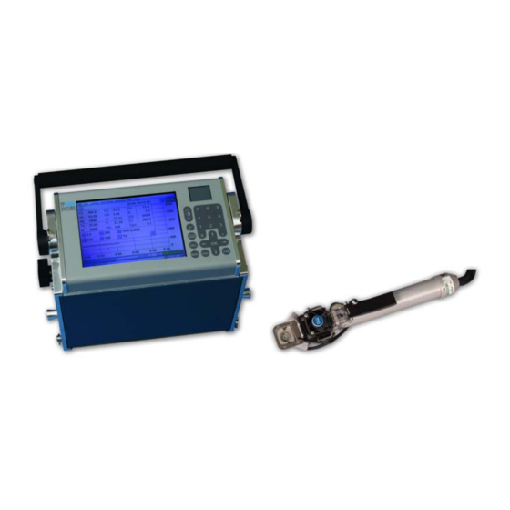
CIRAS-2
Portable Photosynthesis System
Operator‟s Manual
Version 2.04
For Remote Control Software (RCS) Version 1.07 or greater.
© 2010 PP Systems. All Rights Reserved
th
12
May 2010
PP Systems, Inc.
110 Haverhill Road, Suite 301
Amesbury, MA 01913 U.S.A.
Tel: +1 978 834-0505
Fax: +1 978 834-0545
Email:
support@ppsystems.com
Web Site:
http://www.ppsystems.com
Advertisement
Table of Contents

Subscribe to Our Youtube Channel
Related Manuals for PP Systems CIRAS-2


Summary of Contents for PP Systems CIRAS-2
- Page 1 CIRAS-2 Portable Photosynthesis System Operator‟s Manual Version 2.04 For Remote Control Software (RCS) Version 1.07 or greater. © 2010 PP Systems. All Rights Reserved May 2010 PP Systems, Inc. 110 Haverhill Road, Suite 301 Amesbury, MA 01913 U.S.A. Tel: +1 978 834-0505...
- Page 2 This page is left intentionally blank.
-
Page 3: Table Of Contents
Step 7. Connect CIRAS-2/PC interface cable ............22 Step 8. Power on CIRAS-2..................23 Step 9. Close the leaf cuvette ................... 24 Step 10. Start CIRAS-2 RCS program on your computer ......... 24 Familiarizing Yourself with the Measurement Display ..........25 LED Tuning ........................ 25 Gas Exchange Measurement Screen ................ - Page 4 Zero ..............................32 Diff Bal..............................33 Measure [Quit]............................33 Initialise ..............................33 Pulse Alarm ............................34 Simultaneous Measurements With CIRAS-2 and FMS2..............34 Diagnostics............................34 Stored Diff Bal ............................35 Calibration ............................35 Calibration Check ..........................35 Calibration Reset ..........................35 CO2 Midpoint ............................
- Page 5 Air Supply On ........................... 49 Cuvette Flow ............................. 49 Light Type [ _ ] ............................. 49 PAR ..............................49 Energy Factor ........................... 49 Value ..............................49 Cuvette Environment ....................50 Control Types ............................51 CIRAS-2 Operator's Manual Version 2.04 - 3 -...
- Page 6 If performing a basic CO Response: ....................53 Customized Operation of CIRAS-2 with Ambient CO ................. 53 Customized Operation of CIRAS-2 at Humidity Levels Above Ambient ..........54 CIRAS-2 Time ......................54 Analog Outputs ......................54 Analog Outputs ..........................55 O Analog Outputs ..........................
- Page 7 Include File Information ........................89 Export Fields............................. 89 Options ............................. 90 Transferring Data From CIRAS-2 to Your Computer ..........91 PCMCIA Card ............................91 RS232 (Null Modem) Connection ......................91 Establishing An ActiveSync Connection For Data Transfer from UI To PC ........91 CIRAS-2 Operator's Manual Version 2.04...
- Page 8 Installation of USB Drivers On Your PC ................... 93 Establishing An ActiveSync Connection For Data Transfer from UI To PC ........94 Shutting Down the CIRAS-2 System ................95 Measuring Chlorophyll Fluorescence with the CFM ..........96 Getting Started with the CFM ..................96 Firmware &...
- Page 9 1. Fluorescence Induction Analysis (Kautsky Curve)................. 122 2. Quantum Efficiency of Photosystem II ................... 124 Glossary of Fluorescence Terms ................125 Measuring Soil Respiration with CIRAS-2 ............... 127 Soil Respiration Measurement Display ..............127 Prompt ............................... 127 Parameters ............................127 Settings ..............................
- Page 10 Leaf Cuvettes fitted with a FLAT GLASS WINDOW ................151 Leaf Cuvettes fitted with a PLASTIC HEMI-CYLINDER ..............151 CIRAS-2 Settings for Leaf Cuvettes and Probes ............. 152 Appendix 2. CIRAS-2 Consumables and Spares ........... 153 Appendix 3. Photosynthesis Equations Used in CIRAS-2 ........155 CIRAS-2 Operator's Manual Version 2.04...
- Page 11 References ....................... 161 Addendum ........................162 Corrections to Stomatal Resistance Measurements for Differing Transpiration Rates from Upper and Lower Leaf Surfaces ..............162 Magnitude of Errors in RS ..................164 User Notes ......................... 165 CIRAS-2 Operator's Manual Version 2.04 - 9 -...
-
Page 12: Preface
Otherwise, damage may be caused which is not covered under our normal warranty policy. This manual and the information contained within are copyright to PP Systems. No part of the manual may be copied, stored, transmitted or reproduced in any way or by any means including, but not limited to, photocopying, photography, magnetic or other mechanical or electrical means, without the prior written consent of PP Systems. -
Page 13: Service & Warranty
If for some reason, a fault is covered under warranty, it is the responsibility of the customer to return the goods to PP Systems or an authorised agent for repair or replacement of the defective part(s). Contact Information PP Systems, Inc. -
Page 14: Ciras-2 Essentials
Do not use substitute battery chargers or power supplies with CIRAS-2. Avoid allowing water into any CIRAS-2 gas inlets or the leaf chamber. Do not use on wet foliage or attempt to humidify the gas stream by direct artificial introduction of humidified air. -
Page 15: Getting Started
Area of our website: http://www.ppsystems.com/user_registration2.htm At this point we expect that you have completed the CIRAS-2 Tutorial - the Tutorial is a condensed version of the Operator‟s Manual and intended to quickly familiarize you with making basic leaf gas exchange measurements. -
Page 16: Installing Ciras-2 Remote Control Software On Your Computer
1. Copy the contents of the CD ROM Windows folder to a convenient location on your PC local drive (i.e. C:\) and NOT to a network drive. Please note: the current version of the CIRAS-2 software will not allow you to install RCS to a network drive. - Page 17 Getting Started – You can run your RCS software by going to Start, Programs, CIRAS-2 Remote Control Software or by clicking the CIRAS-2 Remote Control Software icon on your desktop screen. The first time that you run RCS the Select User dialog (below) will be displayed on the screen: Later, when you set up your preferences and settings, this information will automatically be saved for you.
- Page 18 After entering a user name, select OK. You will be informed as to the exact location of the file. Click OK to continue. The Preferences dialog will now open. Enter the Com port that is being used with CIRAS-2. The correct COM port MUST be selected for inter-communication between the computer and CIRAS-2.
-
Page 19: Click ? At Any Time For On-Line Help
Open the „Accessory‟ drop down list containing the standard cuvettes and chambers that may be used with CIRAS-2. From this list select „PLC6 (U) 18 mm diameter insert‟ – this is the most common leaf cuvette used with the CIRAS-2 system. By making this selection, various other options will automatically be set to default settings that are standardized for the PLC6 (U) cuvette. -
Page 20: Preparations For Use
At this point you should have installed the CIRAS-2 Remote Control Software (supplied on CD ROM) to the computer(s) you will use to operate CIRAS-2. Both the Windows (for use with your notebook or desktop PC) and Windows CE (factory-installed on the User Interface) versions of CIRAS-2 RCS are virtually identical. -
Page 21: Step 3. Make Leaf Cuvette Electrical And Gas Connections
CIRAS-2 battery packs. Connect the mains power supply (supplied by PP Systems) from the electrical outlet in your lab to the EXT PWR socket located on the electrical/gas connection panel. The power supply is fitted with a special 4-pin plug that is designed to fit only into the EXT PWR socket. -
Page 22: Step 4. Connect Leaf Cuvette Power Cable To External 12V Dc Power Supply
12V battery or power supply. The other end has a white plastic socket which connects to the white plastic plug on the leaf cuvette cable. For example, if your CIRAS-2 system includes a PLC5(C) Conifer Cuvette with the LED light unit, then you must connect to external power due to the additional voltage requirements of the conifer cuvette. -
Page 23: Ciras-2 Console - Front Layout
Preparations for Use – CIRAS-2 Console - Front Layout PCMCIA (“flash card”) UI Reset RS232 Port Port Slot Gas and Zero Air Water Vapor Green Transmission O Control Electrical Columns Equilibrator Light Columns Connections Panel Step 6. Insert CO cartridge... -
Page 24: Co 2 Holder And Regulator Assembly
Connect the opposite end of the cable with the 5-pin plug into the socket labelled “RS232” on CIRAS-2. Align the red dot on the connector so it is at the 12 o‟clock position of the RS232 socket - click into place. -
Page 25: Step 8. Power On Ciras-2
(USB to Serial Bridge) has been assigned for Step 10. Step 8. Power on CIRAS-2 Switch on CIRAS-2 by pressing the red “On/Off” button on the back panel. When powered, the switch should illuminate bright red. The cuvette fans and CIRAS-2‟s internal pumps should be running at this point. -
Page 26: Step 9. Close The Leaf Cuvette
CIRAS RCS will automatically load default settings and begin LED tuning. Within several minutes the CIRAS-2 system will come to its normal operating temperature of 55 °C. During this time you can begin familiarizing yourself with the Parameters Editor and optimizing the CIRAS- 2 system for your needs. -
Page 27: Familiarizing Yourself With The Measurement Display
Measurement mode. This process takes approximately 30 seconds and cannot be interrupted. During this time, CIRAS-2 drives the light unit to a range of different levels in order to establish precise control of light intensity, accounting for sensor changes over time and small differences between different light units that may be used with the CIRAS-2. -
Page 28: Gas Exchange Measurement Screen
Measure Mode. Please note: Changing Settings through the Setup menu are applied globally (see Cuvette Environment on page 50) and will require a new LED Tuning when you enter Recording Mode. CIRAS-2 Operator's Manual Version 2.04 - 26 -... -
Page 29: Measured Parameters
Click the - button to collapse (Numeric Display off) Click the + button to view (Numeric Display on) CIRAS-2 Date and Time is always displayed in normal measurement, and replaced by CIRAS Mode if not. CIRAS-2 Operator's Manual Version 2.04... -
Page 30: Graph Display Options
Refers to current functional mode of CIRAS-2 (e.g. Zero, Diff Bal, Data, etc.) Power Status Power Status of CIRAS-2 and PC. Clicking on the ? button displays a dialog with the status of the CIRAS-2 batteries and PC (if connected). -
Page 31: Ciras-2 Power
From left to right, the first field shows the current Power Source that CIRAS-2 is using. Then follows the Left and then Right CIRAS-2 battery status. The last field is an indicator of the Power Status of the PC. Power Source... -
Page 32: Ciras Rcs Menu Bar
81. Export Data Exports all stored CIRAS-2 Data Files to your desktop PC in a user specified format for importing into spreadsheet applications such as Microsoft Excel. Please note: export of data cannot be performed while recording. If operating the CIRAS-2 from a PC, you will be asked to “work offline” before continuing. -
Page 33: Connect
96. Com Port The proper COM port on your PC must be set correctly in order to work with CIRAS-2. There are 99 COM ports available to the user as described earlier in this manual (above, page 15, 19). -
Page 34: View Setup Details
Initiate a manual ZERO at any time by selecting this option. The Status Bar displays a ZERO message (lower left hand corner of the display) that begins counting upwards. In ZERO mode, the initial air sample entering CIRAS-2 is drawn through the soda lime (Absorber Column 2) to remove CO and then through CIRAS-2 Operator's Manual Version 2.04... -
Page 35: Diff Bal
[10]). Measure [Quit] It terminates a Zero or Diff Bal and returns operation to measure mode. If CIRAS-2 is in the middle of performing a Zero or Diff Bal during a measurement, it can be terminated by selecting Measure [Quit]. -
Page 36: Pulse Alarm
0.14 0.19 The connector to the FMS2 plugs into the Probe socket of CIRAS-2. A pulse on the alarm line (about 140 ms) triggers the FMS2 to record a fluorescence trace. The pulse is triggered when the cuvette record button is pressed, and CIRAS-2 is set to record data direct into its memory or when the PC requests that the pulse is sent. -
Page 37: Stored Diff Bal
CO2 Midpoint on page 147 for further details. Please note that CIRAS-2 Firmware (EPROM) Version 1.67 or greater is required for this function. If unsure of firmware version, see View – Quick Info in the CIRAS menu bar. CIRAS-2 Operator's Manual Version 2.04... -
Page 38: Max C Determination
25 for details. CIRAS Recording Enable/Disable CIRAS-2 Internal Recording. Save up to 820 internal records to CIRAS-2 and initiate a stored data dump from this menu. Please note that this is different than the normal CIRAS-2 recording mode. See CIRAS Internal Recording on page 77 for additional details. -
Page 39: Begin
Exchange on page 59. Please note that for Closed Systems, Recording operates differently. See for example Measuring Soil Respiration with CIRAS-2 on page 127 for more details. Begin Opens the Select Recording Options dialog to name a new file or select an existing file, edit treatment descriptions and select type of recording. -
Page 40: Multiple Record
View Menu Quick Info Opens the CIRAS-2 – Received Setting dialog. Provides information such as the serial number of the instrument, eprom version, and technical information regarding the current configuration of the CIRAS-2 system. It can be viewed at any time by selecting View - Quick Info. To view additional details such as number of free records, Zero mode, Averaging Limit, Probe and Calibration constants, etc., click on the... -
Page 41: Update Parameters
(see above), click the D button in the upper right hand corner of the display. Battery Status Displays the Battery Status of each 12V NiMH battery used with CIRAS-2, and (if present) the PC‟s battery status. See Power Status on page 28 for details. -
Page 42: Help Menu
Help menus. About Select Help - About to see which version of the CIRAS-2 Remote Control Software you are running. Diagnostics Contains information related to the 6 CIRAS-2 Diagnostics topics. -
Page 43: System Setup And Operation
Settings information provides the basis for your individualized use of CIRAS-2 and will be automatically saved for you. Selections made in the Settings dialog are global and apply universally to a CIRAS-2 session, unlike those made with the Control Setpoint buttons, which are temporarily applied to the session. -
Page 44: Add Entry
To create additional PRM Files click Add Entry Name and choose „Default PRM Name 2‟ from the dropdown list. In the resulting dialog click Yes to use the current parameters or No to create a unique set of parameters. Edit the new entry as above. CIRAS-2 Operator's Manual Version 2.04 - 42 -... -
Page 45: Delete Entry
Open the „Accessory‟ drop down list containing the standard cuvettes and chambers that may be used with CIRAS-2. From this list select, for example, the standard automatic leaf cuvette „PLC6 (U) 18 mm diameter insert‟. By making this selection, various other options will automatically be set to defaults for this Accessory. -
Page 46: Add Custom Accessory
PAR sensor and Soil Temperature Probe are detected automatically and do not require selection as Accessories. If you have any questions as to which cuvette or probe type you have, refer to the original paperwork (i.e. invoice from PP Systems), the Appendix at the back of this manual or contact PP Systems. -
Page 47: Light Type
There are three commonly used methods used to measure T which CIRAS-2 makes available to the user depending on the type of leaf cuvette. -
Page 48: Thermistor
). Leaf area also has a significant effect on final calculations of photosynthesis. However, if recalculation of data is required, this can be done fairly easily. See Recalculate Data on page 81. CIRAS-2 Operator's Manual Version 2.04 - 46 -... -
Page 49: Boundary Layer Resistance
CO concentration is steady when the Diff-Bal is performed. Manual with Warnings Perform manual Zeroes and Diff Bal if desired. CIRAS-2 will prompt you when it determines a Zero or Diff Bal is required. Automatic Zeroes and Diff Bal are performed automatically at regular intervals. Leaving „Zero/Diff Bal Mode‟ set to „Automatic‟... -
Page 50: Changes In Zero Readings
Zero Significantly different from previous [79]‟). 2. If more than 4 sets of Stored Zeros are present, CIRAS-2 checks the slope of the data. If the slope falls out of an acceptable range, an Error Code 78 is generated („Zero Showing Progressive Change [78]‟). -
Page 51: Analysis Flow
PAR sensor on the chamber is used to determine PAR (with or without a light unit attached). Please note: if a PP Systems‟ light unit is used and „Use Sensor‟ is not checked, the light unit will turn off. -
Page 52: Cuvette Environment
Control values associated with Cuvette Environment may be changed at any time except during Response Curve recording. CIRAS-2 control variables available with the PLC6(U) automatic cuvette and LED light unit are: CO 0, PAR, temperature and flow rate. -
Page 53: Control Types
20 °C and standard pressure) in the Reference gas stream entering the leaf chamber. If you enter a H2O Setpoint value of 50 (%) CIRAS-2 will rapidly dehumidify the gas stream entering the leaf chamber such that RH in the chamber will be quickly lowered to 30% (or 7.0 mb). -
Page 54: Cuvette (An) Set Mb (0-Dewpoint)
Remember to reconnect the gas connections before proceeding. Depending on cuvette type, enter a PAR Control Setpoint from 0-2,000 µmol m Cuvette Flow Appears as above (see System Setup on page 49.) CIRAS-2 Operator's Manual Version 2.04 - 52 -... -
Page 55: Temperature
Customized Operation of CIRAS-2 with Ambient CO Especially for field work, you may wish to measure gas exchange without actually controlling CO concentrations from CIRAS-2, using instead the naturally fluctuating diurnal CO concentrations in ambient air. To do this: Empty all soda lime from Absorber Column 3 and replace the empty column in the manifold. -
Page 56: Customized Operation Of Ciras-2 At Humidity Levels Above Ambient
CIRAS-2 Time CIRAS-2 can be set to match the exact date and time of the PC (integral PC or Lab PC) or to a different date and time if required. To match the values to the PC, click on Set Values to System Time. -
Page 57: Co 2 Analog Outputs
Reference Voltage Output = 356/2000 x 5.0V = 0.89 V. Example 2. Reference = 356 ppm Low CO = 300 High CO = 400 Then: Reference Voltage Output = ((356-300)/(400-300)) x 5.0V = 2.8 V. CIRAS-2 Operator's Manual Version 2.04 - 55 -... -
Page 58: Automatically Update Ciras
O Reference Voltage Output = (25.56-10.0)/(50-10)) x 5.0 V = 1.945V. Automatically Update CIRAS If checked, after clicking OK in the Settings dialog to save all changes to the PRM file, CIRAS-2 will receive the new parameters. If this is not checked, CIRAS-2 will not be updated. -
Page 59: Graphing Preferences
O). CO2 An. is simply CO2 Ref. + CO2 Diff. Likewise, H2O An. is the H2O Ref. + the H2O Diff. Font Size Choose the font size that best meets your needs – larger fonts for computer RCS display, smaller for the UI when conducting research in the field. CIRAS-2 Operator's Manual Version 2.04 - 57 -... -
Page 60: Time Plot Details
Essentially, it allows you to view a real-time scatter plot, for example, an A/Ci plot. Shown Variable on Y Axis Choose which of the two variables to display as the response (Y-axis) variable, then set the min-max scales for both selected variables as above. CIRAS-2 Operator's Manual Version 2.04 - 58 -... -
Page 61: Observing And Recording Leaf Gas Exchange
Q (PAR) value should be near your Setpoint value (with attached LED light unit) or ambient (if no light unit is not used) Battery voltage for both the left and right batteries should be > 13.0 V if fully charged. CIRAS-2 Operator's Manual Version 2.04 - 59 -... -
Page 62: Select Recording Options
+/- 1 ppm of the set value by using the „Supply (Ref) Set ppm‟ Control Type. The system is functioning properly if the above conditions are observed. If not, please refer to the Troubleshooting Section of the CIRAS-2 Technical Manual available in the User section of our website. Select Recording Options To begin making measurements, select Recording –... -
Page 63: Treatment Editor
„Enabled‟ box to edit „Item Name‟. Enabling/ Disabling an item will determine whether it is displayed as an option during recording. When Recording, each change of Treatment Item is recorded and all subsequent CIRAS-2 Operator's Manual Version 2.04 - 61 -... -
Page 64: Recording Mode
UI (example below), or choose a different location. Click Yes to proceed to Recording Mode. Please note: If CIRAS-2 is actively performing a Zero or Diff Bal, you may receive the following message prior to naming the data file: CIRAS-2 Operator's Manual Version 2.04... -
Page 65: Placing The Leaf In The Cuvette
(Cr). When Ci<Cr there is an instantaneous change in net photosynthesis (Pn) values from a negative rate (respiration) to a positive rate. Simultaneously, the differential CO concentration (Cd) will go into negative values while differential CIRAS-2 Operator's Manual Version 2.04 - 63 -... - Page 66 When readings are stable and you are ready to begin measurements, click the Start button in the Recording window. Depending on the state of your CIRAS-2, the instrument may perform a Zero and Diff Bal. You may also take this opportunity to adjust your Graphing Options, for example, by selecting one or CIRAS-2 Operator's Manual Version 2.04...
-
Page 67: Keypress Recording
Single button in the CIRAS-2 Recording Mode screen. To begin manually recording data, click in the circle next to „Key Press‟ and then click OK. -
Page 68: Timed Recording
Control Setpoints or sample different plants or leaves. Again, select Recording - Begin from the CIRAS-2 main menu. In the Select Recording Options dialog click in the circle next to Timed and then click OK. There are two Timed Recording Options: 1. -
Page 69: Settle Time (Seconds)
Summarizes cumulative recording time based on recording interval, frequency and records. Record Interval (seconds) Refers to the amount of time (seconds) between records. CIRAS-2 transmits data every 1.6 seconds. If an interval has elapsed, the next available record will be taken. -
Page 70: Enable Recording Blocks
When generating Response Curves, it is important to bear in mind the that large changes in a level may cause CIRAS-2 to Zero or Diff Bal during recording, effectively interrupting the measurement. In some cases, a Manual Response may be more suitable than an Automatic Response, as the user initiates recording in a Manual Response where leaf stability may be monitored. -
Page 71: Editing Response Variable Values
(Set Equal), or decrease (Decrement) the „Start Value‟ through your selected range of Levels. The example above shows a constructed response curve that dynamically increases CO only, experimentally subjecting the leaf to 50 ppm incremental changes CIRAS-2 Operator's Manual Version 2.04 - 69 -... -
Page 72: Editing Groups Of Values
(see below). Enter the new value in the field and click on the cell again to register the value in the cell for that specific Response Level. Customize additional Response Levels as desired. CIRAS-2 Operator's Manual Version 2.04 - 70 -... -
Page 73: Enabling Levels
Level 11 now also appears in the lower left field. Repeatedly click the right arrow > button next to the right field until all remaining levels are highlighted (Levels 11-30), then click On/Off to disable the selected levels. CIRAS-2 Operator's Manual Version 2.04 - 71 -... -
Page 74: Recording Options
This applies to the initial settling of the Response Curve measurement and any settle that is caused by a Zero or Diff Bal that occurs during the Response Curve. Zero Settle Time differs from the Level Settle Time set in the Response Editor. CIRAS-2 Operator's Manual Version 2.04 - 72 -... -
Page 75: Steady Pn Options
Level 1, then press the Start button to begin an automatic response curve measurement. You can review details of your Response Levels at any time by clicking on the … button in the Recording CIRAS-2 Operator's Manual Version 2.04 - 73 -... - Page 76 – note „Settling for Level 16 [1:14 of 1:30m]‟ in upper left of display. The corresponding Data Plot view of the A/Ci curve is also shown. Please note: CIRAS-2 firmware is programmed to perform a Diff Bal whenever CO concentration changes exceed 100 ppm or H O partial pressure exceeds 3 mb.
- Page 77 Observing and Recording Leaf Gas Exchange Time Plot Data Plot CIRAS-2 Operator's Manual Version 2.04 - 75 -...
-
Page 78: Batch Response Curves
Please note: For Batch Response Level 1, a Zero is always forced, and the user must indicate that the system is stable. CIRAS-2 Operator's Manual Version 2.04 - 76 -... -
Page 79: Repeat
2 to 10 times. If unchecked, the Response Level only runs once. CIRAS Internal Recording If required, data can be saved directly onto CIRAS-2 memory. From the menu bar select Utilities - CIRAS Recording to record measurements internally to CIRAS-2. The maximum number of records that can be stored internally is 820. -
Page 80: Enable Internal Recording
Apply Internal Recording Updates CIRAS-2 with the new information. Transfer Data To transfer internally stored CIRAS-2 data to your PC, click on the Transfer Data button. Available Please note: „Enable records are transferred from CIRAS-2 into the selected file (dmp extension). - Page 81 The measurement screen will then be displayed and initially CIRAS-2 will zero. CIRAS-2 will then be set to the first set of values. When the graph shows that the readings have stabilized click on Steady. CIRAS-2 will now do a Diff Bal and on completion, set to the next pair of values.
- Page 82 The results are displayed showing the measured values and offsets, and the calculated offsets. You then have the option of accepting or rejecting the offsets. If accepted, CIRAS-2 will use the calculated values as long as the reference concentrations are within the set up range.
-
Page 83: Recalculate Data
The Save Recalculated Data to… dialog will appear. The selected file will be automatically given a .mod extension. The original file (.dat extension) will remain unaltered. Click Save to continue. The CIRAS-2 Photosynthesis Recalculation dialog will appear. Initially, data from the first record stored is displayed. -
Page 84: Processing Options
Export Data on page 88. If not selected, the recalculation file will be loaded according to the options set for viewing files available from the Options, Edit menu. CIRAS-2 Operator's Manual Version 2.04 - 82 -... -
Page 85: Recalculation Values
1 (i.e. 50% Stomata on top surface should be entered as 0.50). Flow rate of the integral air supply. If the CIRAS-2 air Flow supply is used, there should be no need to change this value. - Page 86 Recalculate Data Click on: View session date and time, file name and information related to the CIRAS-2 and General user information. The General tab will open first when Session is selected as described above. To view information related to A/D reads associated with the type of probe (i.e. leaf Probe cuvette) used, system setup, etc.
- Page 87 Recalculate Data View the recording type selected (i.e. keypress, timed, response curve) and Recording associated settings. To view treatment descriptions as they pertain to different plots/records. Treatments View measured/stored data graphically. Graphs CIRAS-2 Operator's Manual Version 2.04 - 85 -...
- Page 88 The field to the right in Plot and Data views lists the original and recalculated variables, and their X- and Y-axis positions are indicated by arrow symbols. CIRAS-2 Operator's Manual Version 2.04 - 86 -...
-
Page 89: Options
Recalculate Data Options With the CIRAS-2 Photosynthesis Recalculation window open, select Options. Options files contain stored options for Recalculation and Export of Data Files. Each Options file is divided into 3 sections for the storage of: Stores the parameters to recalculate and how the file is processed. -
Page 90: Load Output File In Spreadsheet
UI. Export Data This feature allows you to export all stored CIRAS-2 Data Files into a user specified and simplified format for use in spreadsheet applications such as Microsoft Excel. Click on File - Export Data and select the data file (.dat extension) that you would like to export, then select Open. -
Page 91: Include File Information
Export analysis CO (Ca) and H O (Ha). Ca and Ha Export all CO and H O related data. All CO2 and H2O Calculated Export all calculated parameters (Pn, Evap, Gs, Ci) CIRAS-2 Operator's Manual Version 2.04 - 89 -... -
Page 92: Options
(.tab extension) in the format selected under Options (above). After naming the file, click Save. Exportable file types are CIRAS-2 Recorded Data (.dat), CIRAS-2 Internal Records (.dmp) and Closed System Measurements (.csc). Recalculation Data (.mod) is treated as CIRAS-2 Recorded Data. -
Page 93: Transferring Data From Ciras-2 To Your Computer
On the Integral PC (Pencentra), all data files are stored in the following directory: \Storage Card \ Users \ UserName \DataFiles On the PP Systems‟ User Interface (UI), all data files are stored in the following directory: \FlashFX Disk\Users\UserName \DataFiles... -
Page 94: Activesync® Communications Software
COM port (normally COM1) to be used on your PC. Click Ok. 3. Turn the CIRAS-2 on and wait for it to get to the opening Log-in screen. Next, exit from the CIRAS-2 Remote Control Software by clicking on Quit. -
Page 95: For Customers That Are Using The Integral Pc (Pencentra)
Check there is no other task controlling the PC COM port For Customers That Are Using Our User Interface (UI) For all CIRAS-2 customers that have our UI, we‟ve supplied both an RS232 “Null Modem” Data Communications cable and USB cable. -
Page 96: Establishing An Activesync Connection For Data Transfer From Ui To Pc
2. On your PC, start ActiveSync (Must be ActiveSync version 3.7.1 or later). At this stage, it should show that you are not connected. 3. Turn the CIRAS-2 on and wait for it to get to the opening screen. 4. Connect the USB cable between your UI and your PC. -
Page 97: Shutting Down The Ciras-2 System
Remove the entire CO regulator assembly from inside the CIRAS-2 console and keep separate if CIRAS-2 is to be stored in a confined space or container, such as the carrying bag. CO from the cartridge is constantly diffusing, whether or not the regulator assembly is installed in CIRAS-2. If... -
Page 98: Measuring Chlorophyll Fluorescence With The Cfm
It is assumed that you are already familiar with operation of the CIRAS-2 Portable Photosynthesis System. If not, we strongly suggest that you familiarize yourself with the basic operation of the CIRAS-2 system and refer you to the CIRAS-2 Portable Photosynthesis System Tutorial and earlier sections of this Operator‟s Manual. -
Page 99: Power Requirements
TRANS value for the LED light unit (with CFM) is 0.14 for both the CALFLEX and plain glass window. Note, if using our other style light units (i.e. quartz halogen) or sun/sky, please refer to the CIRAS-2 Operation Manual for further information on TRANS factors. -
Page 100: Connecting The Cfm To Ciras-2
Measuring Chlorophyll Fluorescence with the CFM Connecting the CFM to CIRAS-2 All electrical and pneumatic connections must be made before powering up the CIRAS-2. Please pay special attention when connecting all electrical connections to avoid problem associated with damaged connectors (which are quite expensive). -
Page 101: Operation From External Pc
CIRAS-2 and the COM ports have been determined, perform the following to operate the system from an external PC: 1. Connect the CIRAS-2 PC Interface cable (9 pin D - 5 pin Lemo) between the PC serial port (9 Pin) on the back of the PC and the connector labeled “RS232” on the CIRAS-2. -
Page 102: Stand-Alone Operation (User Interface)
Stand-Alone Operation (User Interface) After all electrical and pneumatic connections are made as described in the section Connecting the CFM to CIRAS-2, perform the following to operate the system from the PP Systems‟ User Interface: 1. Switch the “CFM” slide switch to On. -
Page 103: Cfm Operation
Power on CIRAS-2 by pressing the red On/Off switch. Execute the CIRAS-2 Remote Control Software on your PC. The software can be run by going to Start - Program Files - CIRAS-2 Remote Control Software and clicking the CIRAS-2 Remote Control Software icon. -
Page 104: Default Adaptation
For this selection, only steady state fluorescence calculations may be performed (Fo in the Dark / Fs in the Light). CFM Recording Options This allows the user to set up the recording options based on the Default Adaptation selected (i.e. Dark Adaptation, Far Red Adaptation or No Adaptation). CIRAS-2 Operator's Manual Version 2.04 - 102 -... -
Page 105: Dark Period (Minutes)
Depending on the selection under “Default Adaptation”, the user can determine the fluorescence parameter to be calculated after adaptation. Default Adaptation Calculations Performed Dark Adaptation Fv/Fm Fo‟ Far Red Adaptation No Adaptation None CIRAS-2 Operator's Manual Version 2.04 - 103 -... -
Page 106: Cfm Setup
(if Dark Adaptation is selected) or light adapt the leaf sample for each level (if Far Red Adaptation). This is not available if „No Adaptation‟ is selected. CIRAS-2 Operator's Manual Version 2.04 - 104 -... -
Page 107: When A Ciras Record Is Taken, Perform
Same as described above under Setup. The user can set the timing and light sources for the calculation required here. Modulation Beam Opens the Set CFM (Light Unit) Parameters dialog. The user has the ability to enable/disable the modulating beam, set modulating level, and adjust gain. CIRAS-2 Operator's Manual Version 2.04 - 105 -... -
Page 108: Enable Modulating Beam
Once established, there should be no need to change the gain for individual leaves. Perform CFM Tuning Manually begin a CFM tuning – only needed if prompted by CIRAS-2 to do so. CIRAS-2 Operator's Manual Version 2.04 - 106 -... -
Page 109: Cfm Graphing Options
CFM Operation CFM Graphing Options Allows the user to customize the CFM display in CIRAS-2. This function is also available within the main CIRAS Graphing Preferences (Settings – Graph – Preferences). CFM Time Plot If selected, the average fluorescence is plotted as a green line. The Average fluorescence signal is averaged every 1.6 seconds in order to... -
Page 110: Ciras-Cfm Display
(gas exchange and chlorophyll fluorescence), though it is possible to plot the average fluorescence with gas exchange parameters. Gas Exchange Display Chlorophyll Fluorescence Display (CFM) Recd. Click on the Recd button to select calculation types, edit options and see the explanation of calculations. CIRAS-2 Operator's Manual Version 2.04 - 108 -... -
Page 111: Cfm Display Buttons
25). Three sets of projected A/D values will be displayed – these values should be >8000. The cuvette must be empty and the correct cuvette window installed (Plain Glass) for CFM Tuning to complete successfully. CIRAS-2 Operator's Manual Version 2.04 - 109 -... - Page 112 CIRAS-CFM Display CIRAS-2 Operator's Manual Version 2.04 - 110 -...
-
Page 113: Recording Chlorophyll Fluorescence
CFM recording options, click on Keypress Options and then Edit CFM options. In this case, we made the following CFM selections based on Dark Adaptation. After a 30 minute dark adaptation period, the CIRAS-2 will perform an Fv/Fm calculation based on the CFM settings below: CIRAS-2 Operator's Manual Version 2.04... - Page 114 Recording Chlorophyll Fluorescence CFM Recording Options Fv/Fm Options phiPSII Options CIRAS-2 Operator's Manual Version 2.04 - 112 -...
- Page 115 (Hr) should be stable with little differentials for CO (Cd) and H O (Hd) during dark adaptation. At the completion of the dark adaptation period or when you manually end it, the Fv/FM measurement will be initiated and recorded: CIRAS-2 Operator's Manual Version 2.04 - 113 -...
- Page 116 If you would like to view the chlorophyll fluorescence data and trace information associated with the measurement, click on the > button next to the Recd. button on the left side of the lower display: CIRAS-2 Operator's Manual Version 2.04 - 114 -...
-
Page 117: Response Curve Recording With Cfm
CFM options, you can do so here. When your Response Curve-Control Settings are set, click on OK to return to the Response Curve Editor. Any change here will also change the settings in the CFM file. CIRAS-2 Operator's Manual Version 2.04 - 115 -... - Page 118 CFM options and the photosynthesis readings will be based on the settings in the Response Curve Editor. Following the dark adaptation period, the CIRAS-2 will perform an Fv/Fm and the chlorophyll fluorescence measurements you selected, with event markers showing each measurement. To view the fluorescence data and trace associated with the measurement, click on the >...
-
Page 119: Cfm Output
88.), which assigns headings to all CFM measurements and calculation phases. Unlike CIRAS-2 gas exchange data, raw CFM data (.dat) files are not written to output with headings. CFM data files are complex, and can be difficult to interpret without help. In the CIRAS menu go to Help -... -
Page 120: Calculation Error Codes
A single calculation can have one or more errors. Errors 1, 2 and 4 can apply to Fv/Fm calculation. Error 16 can apply to phiPS2 Error 8 can apply to Fo‟ Errors 8 and 16 can apply to phiPSR CIRAS-2 Operator's Manual Version 2.04 - 118 -... -
Page 121: Brief Introduction To Chlorophyll Fluorescence
1991 and Govindjee 1995). Since the work of Emerson et al. (1932) it has been widely accepted that there are two separate photochemical steps during photosynthesis which are associated with different groups of pigments; these CIRAS-2 Operator's Manual Version 2.04 - 119 -... -
Page 122: Techniques For Measuring Chlorophyll Fluorescence
This problem is avoided in instruments such as the HANSATECH FMS2 and in the CFM by using an electronic method, commonly referred to as modulated fluorometry, to separate actinic light from the fluorescence signal (Ögren and Baker 1985). During measurement the tissue sample is exposed to a CIRAS-2 Operator's Manual Version 2.04 - 120 -... - Page 123 (1.8 µsec) with long off period between pulses. The net result is that the integrated amount of radiation incident upon the sample from the modulating beam is CIRAS-2 Operator's Manual Version 2.04 - 121 -...
-
Page 124: Common Fluorescence Measurements
O,I,D,P,S,M,T. With the development of shutter-less high-speed data sampling instruments such as the Hansatech Plant Efficiency Analyser a further (J) peak was discovered in the fast fluorescence rise. This is best observed on a logarithmic plot. CIRAS-2 Operator's Manual Version 2.04 - 122 -... - Page 125 Fast enough time resolution (10 µs) of the Kautsky Curve. Powerful light source A light source providing a minimum of 2,500 µmol m to fully reduce all of the PSII electron acceptors molecules. CIRAS-2 Operator's Manual Version 2.04 - 123 -...
-
Page 126: Quantum Efficiency Of Photosystem Ii
The relatively slow changes in fluorescence events when measuring common light- adapted parameters means that the high-time resolution of fluorescence induction kinetics is not needed. CIRAS-2 Operator's Manual Version 2.04 - 124 -... -
Page 127: Glossary Of Fluorescence Terms
Maximum fluorescence signal from Adapt sample to actinic light, (light-adapted light-adapted leaf following deliver saturating pulse and fluorescence maximum) application of saturating pulse track fluorescence signal. which fully reduced PSII electron acceptors preventing photochemistry. CIRAS-2 Operator's Manual Version 2.04 - 125 -... - Page 128 0.5 * leaf absorption) with incident radiation in Estimated rate of electron transport sample via PAR sensor on flow within the chloroplast. leaf-clip. Leaf-absorption factor must be measured separately with an integrating sphere. CIRAS-2 Operator's Manual Version 2.04 - 126 -...
-
Page 129: Measuring Soil Respiration With Ciras-2
Measuring Soil Respiration with CIRAS-2 Measuring Soil Respiration with CIRAS-2 The CIRAS-2 Measurement Screen is slightly different for Closed System Analysis (e.g. soil respiration with SRC-1 chamber, canopy assimilation with our CPY-4 chamber). The following instructions and corresponding settings assume use of PP Systems‟ SRC-1 soil respiration chamber. For more technical information and details related to electrical and gas connections please refer to the SRC-1 Soil Respiration System Operators Manual for CIRAS-2 ver. -
Page 130: Settings
Soil surface covered by chamber (cm Soil Respiration Operational Settings Go to the Setup –Settings menu to open the CIRAS-2 Settings dialog. Click on the Setup button to view current settings. The following menu will appear: Select „SRC-1 Soil Respiration Chamber‟ from the „Accessory‟ drop down list. Click OK. CIRAS-2 now displays the Soil Respiration Measurement Display (as above). -
Page 131: Chamber Properties
See Add Custom Accessory on page 44. System Type SRC-1 refers to a standard chamber supplied by PP Systems. Recording Parameters Change The maximum amount of change in CO concentration from the start of measurement. The default value is 60 ppm. -
Page 132: Results
Measuring Soil Respiration with CIRAS-2 Results Select from two options - save soil respiration (SR) results as i) g m or ii) SR as µmol m Evaporation (Evap) results as mmol m Data File Used to create new data files. If no file has been selected, you will be prompted when the first records are taken. -
Page 133: Recording In Soil Respiration Mode
Once you have successfully set up the system as described above and with the SRC-1 Soil Respiration Chamber properly connected to CIRAS-2, click the Start button in the upper right display. In the upper left hand display, you will be prompted to “Hold Chamber in air to flush”. Ensure that the chamber is held in the air to allow it to completely flush itself out (the SRC-1 chamber fan should run at a noticeably higher speed during this period). - Page 134 Measuring Soil Respiration with CIRAS-2 up) according to the options in Select File Mode. There is always a final confirmation to verify that the selected file is correct. If you need to change the Plot Number or wish to add a comment between measurements, click on the T button in the upper left hand corner of the display.
-
Page 135: Diagnostics
CIRAS-2 Battery and Board Voltages and Cuvette Voltage if connected. Report Generate Diagnostics Report for Technical Support. CIRAS-2 and the software must be in Measure Mode to enter Diagnostics. (Diagnostics may also be performed during the Warm Up Cycle). Analyser A/D Reads CIRAS-2 Operator's Manual Version 2.04... -
Page 136: Analyser Temperature ( O C)
Excessive differences indicate blockages or pressurisation of the analyzer. Stored Zeros Zero values stored by CIRAS-2 after 30 minutes running. The CIRAS-2 checks the values for changes in the values to warn of zero column exhaustion or deterioration of analyzer performance. -
Page 137: Apply Valves To Measure
Diagnostics Apply valves to Measure Click on this to put CIRAS-2 into Measure Mode. With „Set to Measure‟ selected and after clicking on this option, the values for CO and H O (Reference & Analysis) should drop to a lower value. Stability will depend on the air that is being sampled. -
Page 138: Cuvette Air
The default Probe Type is Manual Cuvette (Set to Auto Cuvette in this example). Please note: Regardless of which probe has been selected in the Parameters dialog, you MUST specify it again in Diagnostics in order to get the appropriate A/D reads for your setup: CIRAS-2 Operator's Manual Version 2.04 - 136 -... -
Page 139: Apply
Diagnostics Click on this if CIRAS-2 is used as a stand-alone Analyzer. Analyser Only Click this if the SRC-1 soil respiration chamber is connected. Sensor or Closed System Click this if OP-1 is connected. Oxygen Probe Click this if a canopy cuvette or CFX-1 is connected. -
Page 140: Apply Analyser Flow Control
Used for testing the cuvette air supply. Flow (mls/min) Click on this so that a new value can be entered. Flow Requested Flow Rate that CIRAS-2 has been set to. Flow Measured Flow rate that is being delivered. Control Setting The current setting for the cuvette air supply pump driver. -
Page 141: Temperature Control
Lamp 2 only applies to the quartz halogen light source (smaller bulbs). Batteries & Voltages Board Voltage Voltage available to CIRAS-2 board. This should be several hundred millivolts less than the battery voltage. Cuvette Voltage Voltage of the external cuvette power source. When an Automatic type of leaf cuvette is connected, this is the voltage measured on the PLC circuit board. -
Page 142: Right Battery Voltage
Current Battery/Power Source Refers to the source of power for CIRAS-2, whether it is battery (left or right) or the external power supply. When the voltage of one battery drops to approx. 10.5V, the CIRAS-2 automatically switches over to the other battery (if fitted). - Page 143 Zero Column (supplied) during the 'Analyser Test' and connecting a Leaf Cuvette during the 'Leaf Cuvette Tests'. Requires i) external CIRAS-2 Power Supply, ii) External Zero Column, iii) fresh chemicals, iv) external power supply to Leaf Cuvette (if needed, e.g. for the PLC5 cuvette or tungsten halogen light source.
- Page 144 You can view the file at any time from the by going to File – View Diagnostics Report from the CIRAS-2 menu bar. You must be OFFLINE to view the file (Connections – Disconnect in the CIRAS-2 menu bar).
-
Page 145: Calibration
The second cause, though fortunately less common, is liquid water through the cells, affecting their reflectivity and therefore the linearity. The only reason to re-calibrate CIRAS-2 is to use your own laboratory standard, rather than relying on our calibration. Regularly check the CIRAS-2 calibration as changes signify instrument problems. For CO... -
Page 146: H 2 O Calibration Sources And Connections
Fill a gas sample bag with the calibration gas direct from the cylinder. Now attach the gas sample bag inlet to the REF AIR IN and the CIRAS-2 will draw out a sample without any risk of pressurization. Please note: Be sure to initially partially fill and empty the bag to ensure that the sample is truly the calibration gas. -
Page 147: Performing Calibrations
Calibration Performing Calibrations Allow the CIRAS-2 to warm-up for at least 30 minutes. From the above notes, connect up CIRAS-2 to the calibration source then from the PC Windows display, select Utilities – Calibration - Start. Next, click on the type of calibration (CO... - Page 148 Calibration Calibration Checking: Connect a vented T Piece to „REF IN‟ and „AIR OUT‟ on the CIRAS-2. Make sure that nothing is plugged into the PLC Socket. If the status values are not OK, check that there is flow from the CO Exhaust (Located on the base of CIRAS-2).
-
Page 149: Calibration Reset
CIRAS-2 will perform a Zero and on completion begin transmitting the calibration data, but the values at this stage are irrelevant. If the Reset Button is clicked, CIRAS-2 will be instructed to reset the Calibration Constants to the Factory Default and CIRAS-2 will then return to the measurement mode using those factors after performing a Diff-Bal. - Page 150 Set the CO Midpoint back to the factory default value. Upon selection of the appropriate option, CIRAS-2 will apply the setting, return to Measure mode and perform a Diff-Bal. The Software will return to the Measurement Screen. If unsuccessful, the “Close the Dialog”...
-
Page 151: Max C Determination
Valve set to 100% (Fully Open) and then with the CO Valve set to 50%. At each stage, CIRAS-2 should be allowed to reach a stable Cr (CO2 Reference) reading. At this point a Zero should be forced. After the Zero, allow the system to re-stabilize. Valve Setting and ZERO can be initiated from the Change/Zero button. - Page 152 After completion of the 100% Step Pc (Max) Pressure Corrected Term Blender Temperature Flow After completion of the 50% Step: Pc (Mid) The MaxC function can be exited at any time by clicking the Quit button. CIRAS-2 Operator's Manual Version 2.04 - 150 -...
-
Page 153: Appendix 1. Cuvettes And Probes
For safe and accurate operation, CIRAS-2 must be set up with control parameters for the type of cuvette that is in use. Cuvettes supplied with CIRAS-2 and the PLC6 (U) will already be labelled. If you are using an older cuvette, you must identify it. The following tables will help. -
Page 154: Ciras-2 Settings For Leaf Cuvettes And Probes
LED with the PP Systems LED light unit and with any fluorescent lights and QI with any incandescent lamps or quartz halogen bulbs. If you are using PLC4 (B/R) or PLC5 (N) (C/P) with a CIRAS-2, then use the settings that are listed for these cuvettes when used with CIRAS-2-1... -
Page 155: Appendix 2. Ciras-2 Consumables And Spares
Water Vapor Equilibrator (For CIRAS-2) 20041-4 Absorber Column only (CIRAS-1 and CIRAS-2) 10063-2 Absorber Column & End Fittings (CIRAS-1 and CIRAS-2) Absorber Column “O” Rings & Filters for CIRAS-2 (1 Set) STD017-2 STD088 GAST-5 Replacement Seals STD044-2 CIRAS Forwarding Pump (GAST) - Page 156 Appendix 2. CIRAS-2 Consumables and Spares Leaf Cuvette Cat. No. Description Leaf Cuvettes & Chambers Spares (for use with CIRAS-1/CIRAS-2) STD010 Cuvette Impeller Blades (* type B,N,C or P) STD011 Cuvette Impeller Motor (for all (B) / V1 (N) STD524 PLC4/5/6 (B) Broad Gaskets, 18mm Diameter, Qty.
-
Page 157: Appendix 3. Photosynthesis Equations Used In Ciras-2
Step 1.0 Calculate the mass flow of air (W) per unit leaf area entering the cuvette The CIRAS-2 mass flowmeter is calibrated to read the volume flow at 20 °C and 1013.25 mb (V ). Molar volume is 22.414 at 0 °C and 1 standard atmosphere (STP). Therefore: Where: a is projected leaf area (cm ). -
Page 158: Step 3.0
Appendix 3. Photosynthesis Equations Used in CIRAS-2 (2.4) Therefore: Clarification of nomenclature: is defined as the partial pressure of water vapor of dry reference air supplied to the cuvette, but not yet inside the cuvette, and therefore uninfluenced by the cuvette stirring fans or the leaf itself. -
Page 159: Step 4.0
Appendix 3. Photosynthesis Equations Used in CIRAS-2 H is calculated from the photon flux incident on the cuvette (Q), taking into account the ratio of infrared to PAR in the light source, transmission through the cuvette window (Trans), and reflection/absorption by the leaf: (H = Q x Trans). -
Page 160: Step 5.0
Appendix 3. Photosynthesis Equations Used in CIRAS-2 (4.5) Then, (4.6) It follows that stomatal conductance is the inverse of stomatal resistance: Step 5.0 Determine the rate of net photosynthesis (A) from the difference between CO concentrations entering (C ) and leaving (C ) the cuvette (5.1) IRGA CO... -
Page 161: Symbol Definitions
Appendix 3. Photosynthesis Equations Used in CIRAS-2 (6.2) Where: Please note: These calculations are based on the following assumptions: the leaf is exposed on both upper and lower leaf surfaces ii) the upper and lower boundary layer resistances are similar iii) stomata are evenly distributed on both upper and lower leaf surfaces. -
Page 162: Physical Constants Used In Equations
Appendix 3. Photosynthesis Equations Used in CIRAS-2 Symbol Calculated Parameter Unit Leaf Temperature °C leaf Δt Temperature difference between the air and the leaf °C Radiation absorbed by the leaf Stomatal resistance to water vapor s mol Stomatal conductance to water vapor... -
Page 163: References
Appendix 3. Photosynthesis Equations Used in CIRAS-2 References 1. Parkinson, K.J. 1983. Porometry in S.E.B. Symposium of Instrumentation for Environmental Physiology. Cambridge University Press. 2. Buck, A.L. 1981. New equations for computing vapour pressure and enhancement factor. Appl. Meteorol., Vol. 20:1527-1532. -
Page 164: Addendum
RS is the total leaf resistance Then for the two leaf surfaces: N and (1-N) are the fractions of the total evaporation E in mol m from the upper (u) and lower (l) leaf surfaces CIRAS-2 Operator's Manual Version 2.04 - 162 -... - Page 165 If we assume that there is equal transpiration on both surfaces (i.e. N = 0.5), then: The error in determination of RS from making the assumption of equal transpiration on both sides of the leaf is (3) - (4). After expansion and simplification this becomes: CIRAS-2 Operator's Manual Version 2.04 - 163 -...
-
Page 166: Magnitude Of Errors In Rs
We can determine the magnitude of the error for various values of RS, RB and N. RS = 1 0.45 RS = 12 0.35 = 0.45 m s mol = 0.3 m s mol 0.25 = 0.15 m s mol 0.15 0.05 % Distribution CIRAS-2 Operator's Manual Version 2.04 - 164 -... -
Page 167: User Notes
User Notes User Notes CIRAS-2 Operator's Manual Version 2.04 - 165 -...
Need help?
Do you have a question about the CIRAS-2 and is the answer not in the manual?
Questions and answers