Table of Contents
Advertisement
Advertisement
Table of Contents

Related Manuals for PP Systems EGM-5


Summary of Contents for PP Systems EGM-5
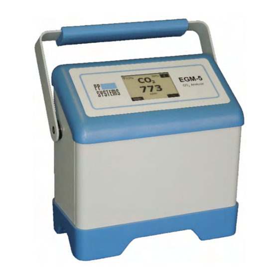
- Page 1 EGM-5 Portable CO Gas Analyzer Operation Manual Version 1.04 2018 PP Systems. All Rights Reserved 1 March 2018 PP Systems - 110 Haverhill Road, Suite 301 -Amesbury, MA 01913 U.S.A. Tel: +1 978-834-0505 Fax: +1 978-834-0545 Email: support@ppsystems.com URL: www.ppsystems.com...
-
Page 2: Table Of Contents
Service & Warranty ............................8 Contact Information ............................8 Unpacking and Storage of Your Equipment ....................8 Unpacking ..............................8 Powering up the EGM-5 for the First Time ....................9 Data Storage ..............................9 Technical Specification ..........................10 Summary of System Design ........................11 Overview and Theory .......................... - Page 3 Reset Abs Settings ........................... 38 Flow Settings ............................ 39 Pump Power ............................. 39 Alarm Sound ............................. 39 Probe Port Settings ..........................40 Probe Port 1 Settings ........................41 Probe Port 2 Settings ........................41 EGM-5 Operation Manual V. 1.04 support@ppsystems.com...
- Page 4 ADC (Analog Digital Converter) Diagnostics ..................84 Zeros Diagnostics ..........................85 Hours Diagnostics ..........................86 Battery Diagnostics ........................... 86 Voltage Diagnostics .......................... 87 Advanced Diagnostics ........................87 Information Menu ............................88 About ............................... 88 EGM-5 Operation Manual V. 1.04 support@ppsystems.com...
- Page 5 Web Pages ............................110 Communication Summary ........................112 Wireless Network Settings........................113 Connecting To EGM-5 via Direct Wireless Connection ..............113 Connecting to EGM-5 via a Local Area Network ................114 Error Messages ............................117 Maintenance .............................. 119 External Air Filter ........................... 119 Absorber Column and CO Scrubber ....................
- Page 6 Appendix 2. WiFi Compliance ........................127 Table C-1 Country Certifications ....................127 Table C-2 Country Transmitter Ids ....................128 Table C-3 Safety ..........................128 Federal Communication Commission Interference Statement ............128 Radiation Exposure Statement ....................... 129 EGM-5 Operation Manual V. 1.04 support@ppsystems.com...
-
Page 7: Welcome
This manual is provided to help you install and operate the equipment. Every effort has been made to ensure that the information it contains is accurate and complete. PP Systems does not accept any liability for losses or damages resulting from the use of this information. -
Page 8: Service & Warranty
PP Systems or an authorized agent for repair or replacement of the defective part(s). Prior to returning equipment to PP Systems for service, you must first get in contact with our Service Manager (service@ppsystems.com) to request a case number for reference and tracking purposes. -
Page 9: Powering Up The Egm-5 For The First Time
Powering up the EGM-5 for the First Time When you receive your new EGM-5 from PP Systems you will need to first connect it up to the external power supply/charger prior to powering up the instrument. To avoid accidental power up during shipment we put the instrument into “Ship Mode”... -
Page 10: Technical Specification
• PP Systems is a registered trademark of PP Systems, Inc. • PP Systems is continuously updating its products and reserves the right to amend product specifications without notice. • All brand names are trademarks or registered trademarks of their respective owners. -
Page 11: Summary Of System Design
Summary of System Design Overview and Theory The EGM-5 is designed to function as a self-contained instrument for continuous measurement of CO air. Its open-path design allows for continuous, unattended air sampling, as the pump introduces fresh sample gas to the essential component, the IRGA (infrared gas analyzer). - Page 12 Some changes may require recalibration, although one of the strengths of the EGM-5 is that recalibration is not a routine (annual) maintenance task as a result of our innovative “Auto-Zero” function. Our Auto-Zero function corrects for nearly all changes that result in calibration drifts.
-
Page 13: Optional Sensors For Use With Egm-5
Readings are displayed and recorded in absolute vapor pressure (mb). Recalibration of this sensor is not necessary. WiFi Optional WiFi is available for use with the EGM-5. Refer to Wireless on page 96 for more information. EGM-5 Operation Manual V. 1.04 support@ppsystems.com... -
Page 14: External Sensors/Chambers
The following sensors/chambers are external to the EGM-5 and electrical connection is made to the Probe Ports (Probe 1 and Probe 2) located on the back of the EGM-5. See Probe Port Settings on page 40 for more information for proper connection. Gas connections (if applicable) are made to the “Gas In”... -
Page 15: Src-2 Soil Respiration Chamber
It also includes sensors for measurement of air temperature and PAR within the chamber. There are two gas connections required, one to the GAS IN port and the other to the GAS OUT port on the EGM-5. •... -
Page 16: Stp-2 Soil Temperature Probe
Soil Moisture and Soil Temperature Sensor An optional soil moisture and soil temperature sensor (HydraProbe II - Stevens Water Monitoring Systems) is available for use with the EGM-5. It is an all-in-one, in-situ sensor that can measure both soil moisture and soil temperature. -
Page 17: System Power
System Power The EGM-5 has an internal, rechargeable lithium ion battery pack capable of providing continuous power to the instrument for up to 16 hours. The EGM-5 is supplied with an external AC power adapter to charge and/or power the EGM-5. -
Page 18: Getting Familiar With The Egm-5
Touch Display The EGM-5 features a 2.7” a-Si, active matrix TFT, Electronic Paper Display (EPD) touch panel. The panel has such high resolution (117 dpi) that it is able to easily display fine patterns with excellent readability under sunlight conditions. Due to its bi-stable nature, the EPD panel requires very little power to update and needs no power to maintain an image. -
Page 19: Navigation Using The Touch Display
Power Switch The power switch is located in the upper left hand corner of the back panel. To power up the EGM-5 simply push in the switch. When power is on the illumination ring around the switch will turn blue. To turn off, simply press the switch again bringing it back to the flush position. -
Page 20: Ext Power Jack
If the EGM-5 was put into ship mode, it will not power on until external power is applied. To bring the EGM-5 out of ship mode, first connect external power to the instrument, and then turn it on by pressing the “ON/OFF”... -
Page 21: Usb Flash Drive Port
Measure Settings. See Memory Measure Settings on page 48 for more information on this. USB PC Port The USB PC Port (USB Mini-B) can be used to connect the EGM-5 to a PC. Measured data is continuously sent through this port. The PP Systems’ GAS software or a terminal emulation program (i.e. -
Page 22: Terminal Block
The relays are rated for 30 VDC at 1A or 125 VAC at 0.3 A. The 5V output could be connected to one side of these relays to create a digital output signal. Relays can also be used to trigger an external device such as a computer or warning light. EGM-5 Operation Manual V. 1.04 support@ppsystems.com... -
Page 23: Recommended Cable Interface
Recommended Cable Interface When connecting up to external devices via the EGM-5 terminal block we recommend the following cable type and lengths. EGM-5 Terminal Block Shielded cable to Data Logger or Programmable Logic Controller Typical cable Belden 8413 2C 24 Shielded. Length 10 Ft Maximum. -
Page 24: Absorber Column And Co Scrubber
Settings on page 34. Important Note It is critical that the soda lime is fresh to ensure that the EGM-5 receives a good zero for long term calibration and stability of the CO signal. At present, both self-indicating and non-indicating soda lime can be used with the EGM-5. -
Page 25: Routine System Checks Before Starting
Routine System Checks Before Starting The EGM-5 is designed to operate with minimal maintenance. The basic routine system checks are as follows: • Make sure the external air filter (Part No. STD558) is fitted to the GAS IN port. This will ensure that the sample air is filtered before entering the system. -
Page 26: Touch Display Overview
Touch Display Overview The flowchart on the following page describes an overview of the touch display for the EGM-5. When the instrument is first powered up, there is a brief period where the Splash screen is shown. After this time, the instrument goes into the warm-up period which is approximately 10-15 minutes and the Measure screen is displayed. - Page 27 Memory Ship Mode Flow Graph Host Port Alarm Sound Reset WiFi Probe Port WiFi Power Diagnostics Calibration Info Processes Menu Menu Menu About Zeros Contact Hours Touch Cal Custom Battery Injection Voltages Static Advanced EGM-5 Operation Manual V. 1.04 support@ppsystems.com...
-
Page 28: Splash Screen
Splash Screen The Splash screen is always shown on the display when the EGM-5 is off. When the instrument is first powered up, the Splash screen is displayed momentarily followed by the Measure screen displaying CO in large text. Measurement Mode The Measurement Mode is comprised of four screens: 1. - Page 29 The percentage value in the top right corner (98%) is the percentage of absorber column remaining. The “Z” button in the top right corner performs a zero when pressed. The Status Box informs the user of any status or error messages. EGM-5 Operation Manual V. 1.04 support@ppsystems.com...
-
Page 30: Readings Screen
The Readings Screen displays the values of six parameters in real time; CO O, O , Temperature, Flow Rate, and Pressure. All of these sensors (if included) are located inside the EGM-5 console. Every EGM-5 will include CO , Pressure and Flow Rate. If the optional H... -
Page 31: Probe Screen
The Probe Screen displays the values of six parameters in real time; CO , PAR, Aux(ANALOG IN), air temperature (Tair), soil temperature (Tsoil) and soil moisture (Msoil). All readings, with the exception of , are based on optional external sensors which may be used with the EGM-5. Readings Screen 2 ♥ (Heartbeat) Pulses on and off to indicate that the system is powered and operating. - Page 32 The x-axis maximum is a fixed value of about 4 minutes. The maximum CO value can be set in the Graph Settings screen. See Graph Settings on page 45 for more details. EGM-5 Operation Manual V. 1.04 support@ppsystems.com...
-
Page 33: Main Menu
For example, Settings Menu 1 contains the first tier of major settings for the EGM- 5. Settings Menu 2 contains the second tier set of settings for the EGM-5. Settings Menu 3 contains options for adjusting the Measurement Format and Interval for the Host, WiFi, and Memory data outputs. -
Page 34: Settings 1 Menu
Settings 1 Menu This menu contains the first tier and most common settings for the EGM-5 including the Zero, Alarms, Reset Abs (Reset Absorber Column), Flow, Alarm Sound and Probe Ports settings. Settings 1 Menu Zero Change/view the settings of the zero parameters (zero type and time interval for performing zeros). -
Page 35: Zero Type
Then select the Back button to return to the Zero Settings screen. The Zero Settings screen will return with the updated Zero Type value in the button box. Press the “Back” button to return to the Settings 1 Menu. EGM-5 Operation Manual V. 1.04 support@ppsystems.com... -
Page 36: Zero Time
Zero Type Settings Automatic This is the recommended Zero Type. The EGM-5 performs a zero on start up, then again after 3 minutes, then again after 6 more minutes, then after 12 minutes, then every 20 minutes thereafter. The Zero Time interval is fixed at 20 minutes. -
Page 37: Alarms Settings
This function allows the user to change/view the low (ALARM1) and high (ALARM2) alarm functions that are built into the EGM-5. An alarm consists of an audio beep (if enabled in the Alarm Sound Setting screen), an information message in the Status Box in the Measurement Mode screens and a relay switch closure. -
Page 38: Low Co 2 Alarm Setting
Setting, select the button to the right of the “Low CO2 (ppm):” text. The numerical keypad will appear, allowing the user to enter a new value. The EGM-5 is supplied with a factory default low alarm setting of 250 ppm. A low CO value is typically the result of one of the following scenarios: •... -
Page 39: Flow Settings
Flow Settings This function allows the user to change/view the Flow rate of the EGM-5. Flow Flow (cc/min) Displays the real-time value of the Flow rate (cc/min). Pump Power (%) Sets the % power of the pump. The range is 0-100%. -
Page 40: Probe Port Settings
This function allows the user to change/view the probes that are connected to ports 1 and 2. Probe Port Settings Probe Port 1 Sets port 1 probe type. Probe options are: Standard, Quantum, Soil Temperature, and Soil Moisture. Back Button Returns to the Settings 1 Menu. EGM-5 Operation Manual V. 1.04 support@ppsystems.com... -
Page 41: Probe Port 1 Settings
CPY-5 Canopy Assimilation Chamber • TRP-3 Temperature/PAR Probe There is no need to change or set the Probe Port type, the EGM-5 will recognize the Probe that is attached to the Probe Port 2 and make the appropriate setting internally. Important Note If you are connecting two probes to the EGM-5 simultaneously, any non-PP Systems manufactured sensors probes must be connected to Probe Port 1. -
Page 42: Settings 2 Menu
Settings 2 Menu This menu handles the second tier of settings for the EGM-5 including the Analog, Averaging, Graph, EGM ID, About and Display settings. Settings 2 Menu Analog Change/view the analog output. This parameter controls the voltage output of the Digital to Analog (D/A) converter in the EGM-5. -
Page 43: Averaging Settings
This function allows the user to change/view the CO averaging method used by the EGM-5. The default EGM-5 averaging window is 1 second long. An optional running average function is available to improve resolution and reduce the effect of transient fluctuations. -
Page 44: Egm Id
Returns to the Settings 2 Menu. EGM ID To change the EGM ID, select the button to the right of the “EGM-5 ID:” text. The EGM ID settings will be displayed, with the current selection indicated. EGM-5 Operation Manual V. 1.04... -
Page 45: Graph Settings
Press the radio button for the desired setting and then the Back button. The Graphic Settings screen will return with the updated Max CO value in the button text. Once the Max CO Setting is as desired, press the “Back” button to return to the Settings 2 Menu. EGM-5 Operation Manual V. 1.04 support@ppsystems.com... -
Page 46: Settings 3 Menu
Settings 3 Menu This menu contains a number of settings for the EGM-5, including the Host, WiFi, Memory, Host Port, Reset WiFi, and WiFi Power settings. Settings 3 Menu Host Configures the data format and time interval at which measurement data is sent to the Host via a terminal emulation program (e.g., HyperTerminal or... - Page 47 See numerical keypad description under Zero Time on page 36 for more details. Press the “Back” button to return to the Settings 3 Menu. EGM-5 Operation Manual V. 1.04 support@ppsystems.com...
-
Page 48: Wifi Measure Settings
These settings control the format of measurement data, as well as the interval at which it is saved to the flash drive. See USB Flash Drive (Memory Stick) on page 89 for more details. EGM-5 Operation Manual V. 1.04 support@ppsystems.com... -
Page 49: Host Port
Press the “Back” button to return to the Settings 3 Menu. Host Port This function allows the user to change/view the settings of the port connection used by the EGM-5. This parameter sets the port connection to either USB or WiFi. Refer to the Digital Communication Protocols and Software on page 96 for more information on this topic. -
Page 50: Reset Wifi
This function allows the user to initialize the onboard WiFi device to factory default settings, if the WiFi option is installed. Reset WiFi Starts the initialization process to restore WiFi configuration to factory defaults. Returns to Settings 3 Menu without performing initialization. EGM-5 Operation Manual V. 1.04 support@ppsystems.com... -
Page 51: Wifi Power
Press the desired setting and then the Back button. The WiFi Power screen will return with the updated WiFi Power value in the button text. Press the “Back” button to return to the Settings 3 Menu. EGM-5 Operation Manual V. 1.04 support@ppsystems.com... -
Page 52: Settings 4 Menu
Settings 4 Menu This menu contains a number of settings for the EGM-5 including the Set Clock, Defaults, and Ship Mode settings. Settings 4 Menu Set Clock Set/Check the system clock (date and time). Defaults Initializes EGM-5 back to factory default settings. -
Page 53: Defaults
Refer to the Get/Set Parameter Values Table on page 106 for more details. Ship Mode This function allows the user to put the EGM-5 into ship mode. The EGM-5 will not respond to presses of the On/Off button. This mode ensures that the unit is not inadvertently powered on during shipment. In order to take it out of ship mode, the EGM-5 needs to be connected to the power supply/charger provided with the instrument. -
Page 54: Processes
Setting 4 Menu. Important Note In order to get the EGM-5 out of “Ship Mode” you must first connect the power supply/charger to the EXT POWER jack before turning the instrument on. If you do not have the power supply/charger connected you will not be able to power up the instrument. - Page 55 Important Note. The above values are based on the default volume of the SRC-2 Soil Respiration Chamber only. You must remember to account for any volume changes for proper calculation of rates. If using collars, please make sure that you adjust the volume accordingly. EGM-5 Operation Manual V. 1.04 support@ppsystems.com...
- Page 56 Valid entries are between 5 – 150 seconds. Stop Stops the SRC process and returns to the Processes Menu. Status Box Any information or error messages are displayed here. Right Arrow Continues to SRC – Other Settings menu (Step 4). EGM-5 Operation Manual V. 1.04 support@ppsystems.com...
- Page 57 (ppm). Countdown in seconds, from 25 to 0. Stop Stops the SRC process and returns to SRC – Other Settings menu (Step 4). Status Box Any information or error messages are displayed here. EGM-5 Operation Manual V. 1.04 support@ppsystems.com...
- Page 58 Data Plot Screen (Step 7) This screen displays present values and a graphical representation of the data gathered during the current session. C: 603 1.91 -0.77 Plot 1 maxDC 50 maxDT 120 Status Box Abort EGM-5 Operation Manual V. 1.04 support@ppsystems.com...
-
Page 59: Cpy (Canopy Assimilation Chamber) Process
The data is checked in the quadratic fit to determine if the data is linear. While the EGM-5 is in the CPY measurement mode, additional data is added to the output data string: change in CO (dC), process time (dT), Linear respiration rate (L), and Quadratic respiration rate (Q). - Page 60 Important Note. The above values are based on the default volume for the CPY-5 Canopy Assimilation Chamber only. You must remember to account for any volume changes in order for the instrument to properly calculate assimilation rates. If using collars, please make sure that you adjust the volume accordingly. EGM-5 Operation Manual V. 1.04 support@ppsystems.com...
- Page 61 Valid entries are between 5 – 150 seconds. Stop Stops the CPY process and returns to the Processes Menu. Status Box Any information or error messages are displayed here. Right Arrow Continues to CPY – Other Settings Menu (Step 4). EGM-5 Operation Manual V. 1.04 support@ppsystems.com...
- Page 62 Current measurement of CO concentration (ppm). Countdown in seconds, from 25 to 0. Stop Stops the CPY process and returns to CPY Step 4. Status Box Any information or error messages are displayed here. EGM-5 Operation Manual V. 1.04 support@ppsystems.com...
- Page 63 CPY Data Plot Screen (Step 7) This screen displays present values and a graphical representation of the data gathered during the current session. C: 603 1.91 -0.77 Plot maxDC 25 maxDT 30 Abort Status Box EGM-5 Operation Manual V. 1.04 support@ppsystems.com...
-
Page 64: Custom Process
Custom Process This process is available for users that want to use their own custom chambers with the EGM-5. Since it is assumed that you are using your own chambers there are no “defaults” built into the system. It is your responsibility to make sure that you enter the appropriate values where required in order to ensure proper calculations. - Page 65 Important Note. You must remember to account for any volume changes in order for the instrument to properly calculate assimilation rates. If using collars, please make sure that you adjust the volume accordingly. EGM-5 Operation Manual V. 1.04 support@ppsystems.com...
- Page 66 Valid entries are between 5 – 150 seconds. Stop Stops the Custom process and returns to the Processes Menu. Status Box Any information or error messages are displayed here. Right Arrow Continues to the Custom – Other Settings menu (Step 4). EGM-5 Operation Manual V. 1.04 support@ppsystems.com...
- Page 67 Continues to the Custom – Start Measuring screen (Step 6). Note: It is up to the user to determine the amount of time required to flush a custom chamber. Status Box Any information or error messages are displayed here. EGM-5 Operation Manual V. 1.04 support@ppsystems.com...
- Page 68 Custom Data Plot Screen (Step 7) This screen displays present values and a graphical representation of the data gathered during the current session. C: 603 1.91 -0.77 Plot maxDC 25 maxDT 30 Status Box Abort EGM-5 Operation Manual V. 1.04 support@ppsystems.com...
- Page 69 Process data is discarded. Status Box Any information or error messages are displayed here. New Button Stops the Custom process and returns to Custom – Other Settings (Step 4). Results are saved to the USB flash drive. EGM-5 Operation Manual V. 1.04 support@ppsystems.com...
-
Page 70: Injection Process
The injection process is a technique used to measure the concentrations of small samples of gas, usually collected in sampling jars and transferred to the EGM-5 with a syringe. The injection process is an improvement over static sampling and yields more reliable and consistent results. - Page 71 To begin a sample injection measurement, first fill the absorber column of the Sample Injection Kit with fresh soda lime and ensure it is oriented vertically throughout the process. Connect the open end of the kit to the GAS IN port on the back of the EGM-5. Injection – Start Process Menu Back Button Returns to the Processes Menu.
- Page 72 Sample Number Sample number of measurement. Button Stop Button Stops the Custom process and returns to the Processes Menu. Start Button Starts the Injection Process and displays the Injection Baseline Phase screen (Step 4). EGM-5 Operation Manual V. 1.04 support@ppsystems.com...
- Page 73 Proceeds to Measuring screen (Step 5). Injection Step 5 – Baseline Phase This is the Baseline Phase. For the first 10 seconds, the EGM-5 will record the baseline reading, which is the CO concentration of the air before the sample is injected (typically 0 ppm). After 10 seconds the Injection Phase begins.
- Page 74 The injection rate should not exceed 3 ml/second to avoid over-pressurization of the system (in other words, it should take the user at least 3 seconds to inject a 10 ml syringe). EGM-5 Operation Manual V. 1.04 support@ppsystems.com...
-
Page 75: Static Process
GAS OUT rather than having the sample pumped through it. This is normally done using a syringe with 1/8” tubing on the end which can easily fit over the GAS OUT port on the EGM-5. For static measurements injected directly into the “Gas Out” port, we recommend a minimum sample volume of 5 Note: The system will still perform its regularly scheduled zeros even if a Static measurement is ongoing. - Page 76 Confirms and starts the Static process by displaying the Static Data Plot screen (Step 2). Static Data Plot (Step 2) Upon entry to this screen, a zero will be performed. 1022 180 sec 1000 ppm Z 24.0 Abort EGM-5 Operation Manual V. 1.04 support@ppsystems.com...
-
Page 77: Calibration
Sensor and the Touch Screen. Calibration Menu Initiates CO calibration. Initiates O calibration. Touch Cal Calibrates the touch screen display. Back Button Returns to the Main Menu. Status Box Any information or error messages are displayed here. EGM-5 Operation Manual V. 1.04 support@ppsystems.com... -
Page 78: Co2
1. To avoid excess pressure in the sample cell and possible damage to the analyzer, you must place a T-fitting between the reference gas source and the GAS IN port on the EGM-5. One end of the T- fitting should be left open in order to relieve excess pressure, as follows: EGM-5 Operation Manual V. - Page 79 350 – 400 ppm. 5. The EGM-5 will then perform a zero. At completion of successful zero, a similar message to the following will be displayed: 6. Note, the displayed value may not be the value you entered in step 3 above. When the Actual CO2 value has stabilized (i.e., not changing by more than 1 ppm after 30 seconds), press the Right...
-
Page 80: O 2 Calibration
The Back button returns the user back to the Main Menu. Calibration This function allows the user to recalibrate the internal O sensor used with the EGM-5. Before calibrating, confirm that: • The WMA-5 has been on for at least 30 minutes. - Page 81 1. To avoid excess pressure in the sample cell and damage to the analyzer, you must place a T-fitting between the reference gas source and the GAS IN port on the EGM-5. One end of the T-fitting should be left open in order to relieve excess pressure, as follows:...
- Page 82 If the process is unsuccessful, the message “Calibration: failed(xx).” will be displayed, where xx is the error code. See EGM-5 Command Set Table on page 96 for a description of calibration error codes.
-
Page 83: Touch Calibration
Touch screen to continue. NOTE: This function can also be initiated by holding a finger on the screen while powering up the EGM-5. If your touch screen is not reacting to your touch: 1. Turn the instrument off. -
Page 84: Adc (Analog Digital Converter) Diagnostics
O sensor voltage. Advanced Displays more advanced diagnostics functions. These functions are password protected, and are for PP Systems use only. Back Returns to the Main Menu. ADC (Analog Digital Converter) Diagnostics This function allows the user to change/view the Diagnostic Mode, initiate a zero and view A/D count readings. -
Page 85: Zeros Diagnostics
400 ppm. Zero Puts the EGM-5 into “Zero” mode. In “Zero” mode, the A/D value for CR should read approximately 40000-50000 if fresh soda lime is present in the absorber column. The CR value in “Zero” mode should always be greater than the CR value in “Measure”... -
Page 86: Hours Diagnostics
Time Left (M) Displays the estimated remaining run time in minutes assuming the average current does not change. A value of 65535 is displayed during battery charging. Back Returns to the Diagnostics Menu. EGM-5 Operation Manual V. 1.04 support@ppsystems.com... -
Page 87: Voltage Diagnostics
Returns to the Diagnostics Menu. Advanced Diagnostics This screen prompts the user to enter a password in order to view advanced diagnostics features. These functions are reserved for PP Systems service & troubleshooting use only. Advanced Diagnostics **** Displays a number entry screen for the operator to enter their PIN. -
Page 88: Information Menu
Displays the IRGA serial number. IRGA VN Displays the IRGA version number. Display VN Displays the Display version number. Back Button Returns to the Settings 2 Menu. Press “Back” to return to the Info Menu. EGM-5 Operation Manual V. 1.04 support@ppsystems.com... -
Page 89: Contact
Data recording begins when a flash drive is inserted into the USB port on the EGM-5 unless the Interval is set to 0 seconds under “Memory Measure Settings”. Data recording ends when the flash drive is removed from the USB port. - Page 90 Even if the Measure Interval is set to 0, Zero Operations and Process data are still sent to the USB, even though CO measurement data is not. Refer to Error Messages on page 117 for disk errors. EGM-5 Operation Manual V. 1.04 support@ppsystems.com...
-
Page 91: Data Storage/Measure Format Settings Table
Parameter 3 Parameter 4 Parameter 5 Process Data Fields The process data fields are based on the measurement mode used with the EGM-5. The 5 different modes available are: 1. Measure mode 2. SRC or Custom mode 3. CPY Mode 4. - Page 92 Syringe sample volume (cc) Parameter 4 Base Baseline (ppm) Parameter 5 Integration value (ppm) Process Data Format (Static mode) Parameter 1 Process Parameter 2 Parameter 3 Process runtime in seconds Parameter 4 reading (ppm) Parameter 5 EGM-5 Operation Manual V. 1.04 support@ppsystems.com...
-
Page 93: Measure Format Settings Table
M3 is Header, Measured data, and Probe data only. The parameters are comma delimited. There are 17 fields. An example is: M3, 03/06/15, 09:32:15, 1, 0003, 1094, 1004.2, 327, 0.0, 00.0, 20.41, 00, 0.000, 825, 23.4, 25.7, 12<CR> EGM-5 Operation Manual V. 1.04 support@ppsystems.com... - Page 94 M5, 03/06/15, 09:32:15, 1, 0003, 1094, 1004.2, 327, 0.0, 00.0, 20.41, 00, 0.000, 0, 23.4, 0, 0, 1 ,76 ,89.56, 7.231, 480<CR> The format is as follows: • M5: Specifies the data format. • Date: dd/mm/yy • Time: hh:mm:ss • Plot No: 0-999 EGM-5 Operation Manual V. 1.04 support@ppsystems.com...
- Page 95 Temperature Probe2 A/D Counts: Proportional to the temperature of probe • Lamp A/D Counts: Proportional to lamp current. • Last Zero CO : Reports A/D counts of the last zero value. • System Error: Displays error code message. (See Error Messages table) EGM-5 Operation Manual V. 1.04 support@ppsystems.com...
-
Page 96: Digital Connection Methods
2. Wireless (if WiFi Option is installed). A USB cable (Mini-B to Type A) can be used to connect the EGM-5 to a host device such as a PC, laptop or tablet. This cable is supplied by PP Systems with every EGM-5. When using a terminal emulator, the COM port settings to communicate with the EGM-5 are: 19200 baud, 8 bit, 1 stop, no parity, no flow control. - Page 97 Depending on the value of the CRC parameter, a CRC will/will not be appended to the command received from the EGM-5. If the CRC parameter value is ‘0’ (CRC Off), no CRCs will be appended to any of the commands received from the EGM-5. If the CRC parameter value is ‘1’ (CRC On), CRCs will be appended (including the ‘C’) to all commands received from the EGM-5.
-
Page 98: Egm-5 Auto Strings
Auto “V” String (Versions) This is sent once right after the EGM-5 is powered on, or if the system is reset. The V string contains the serial numbers and software versions of the EGM-5 controller, the IRGA and the Display. -
Page 99: W" String (Warm Up)
“Z” String (Zeroing) The Z string indicates a zero in progress. During a zero operation, the EGM-5 transmits the Z string every 1 second, until the end of the zero operation. No “M” strings are sent during this time. This command can be initiated by the user or by the EGM-5 itself. -
Page 100: Egm-5 Command Set Table
Battery Capacity (%) = 100% Battery Voltage (Volts) = 7.2 Volts Battery Current (Amps) = 0.546 Amps Battery time remaining = 752 minutes Absorber remaining (%) = 99.1% C,d,a,c Character “C” Command (Calibration) with Parameters d = device EGM-5 Operation Manual V. 1.04 support@ppsystems.com... - Page 101 Sent from Host: F,1<CR> Received from EGM-5: +<CR> In this example, Zero Valve would be set to on. Character “G” Command (Get Setting) with Parameters This command gets a parameter stored in EEPROM (non-volatile memory). x EGM-5 Operation Manual V. 1.04 support@ppsystems.com...
- Page 102 This command returns five system voltage measurements in volts. External Voltage, System Voltage, Flow Sensor Voltage, AUX1 (Analog Output) Voltage and O Sensor Voltage are sent in order in comma-delimited format. Example: Sent from Host: N<CR> Received from EGM-5: EGM-5 Operation Manual V. 1.04 support@ppsystems.com...
- Page 103 EEPROM. A ‘G’ command is returned to confirm that the request was accepted. See Get/Set Parameter Values Table on page 106. Example: EGM-5 Operation Manual V. 1.04 support@ppsystems.com...
- Page 104 Received from EGM-5: +<CR> T,04,42,15,05,01,15<CR> Sent from Host: T,3,11<CR> Received from EGM-5: +<CR> T,4,42,11,05,02,15<CR> In this example, the hour was changed from 10 to 11. All other values stayed the same. Character “V” Command (Get Versions) EGM-5 Operation Manual V. 1.04 support@ppsystems.com...
- Page 105 This command initiates a zero. During a zero operation, the EGM-5 transmits a Z string every second until the end of the zero operation. No “M” strings are sent during this time. This command can be initiated by the user or by the EGM-5 itself. Example: Sent from Host: Z<CR>...
-
Page 106: Get/Set Parameter Values Table
EGM-5. Web Monitor Adds terminator to strings sent to 0=Off; 1=On the WiFi Port to use for web pages Host Serial Selects which Serial Host input to 0=USB use: USB or WiFi 1= WiFi EGM-5 Operation Manual V. 1.04 support@ppsystems.com... - Page 107 Flow Rate Presently ignores setting value 0 - 600 But sends back actual flow rate *These parameters’ values will not be affected by restoring to defaults (Main > Settings > Settings 4 > Defaults). EGM-5 Operation Manual V. 1.04 support@ppsystems.com...
-
Page 108: Gas (Gas Analysis Software)
Double click this icon to start GAS. Click Choose Device and choose EGM-5. A new EGM-5 tab window will appear. Next, click the Connect button. In the top left corner, a box will appear listing all available EGM-5 devices. Select one and click OK. EGM-5 Operation Manual V. 1.04... - Page 109 After clicking OK, the main measurement screen will be displayed. Note: In the top left area, the device name (e.g., EGM-5, SBA-5 or WMA-5), serial number, and COM port are all displayed. Data is displayed both graphically and numerically. GAS gives the ability to log past data activity in a current session (Save Log) or record data (Start Record) for a time segment.
-
Page 110: Web Pages
The Splash Screen is the first screen displayed. There are two buttons the user can choose from: Main and Settings. To return to the Splash screen while in any other screen, click the PP Systems logo in the top left corner of the screen. - Page 111 The Settings screens are interactive and allow the user to make changes to a number of EGM-5 settings. Note: For this to work properly, the EGM-5 needs to be configured with Host set to WiFi (Main > Settings > Settings 3 > Port). Also, the Host Measure Interval should be 0 (Main > Settings > Settings 3 > Host).
-
Page 112: Communication Summary
The following table summarizes the communication methods and protocols described in the preceding sections. In addition, other capabilities exist within the WiFi option that may be useful to some users attempting to write custom code on a wireless connection – please contact PP Systems for more information. -
Page 113: Wireless Network Settings
EGM-5 is connected to the wireless device. When more than one EGM-5 is to be used, it is recommended to power on only one EGM-5 at a time at first, then change the SSID (described in step 9) to a unique name.) 4. -
Page 114: Connecting To Egm-5 Via A Local Area Network
Connecting to EGM-5 via a Local Area Network The following steps will allow the EGM-5 to connect to an existing router or wireless access point and enable connections over a Local Area Network (LAN). Once the EGM-5 is connected to a LAN, any computer or wireless device that is also connected to that LAN can view the EGM-5 web pages. - Page 115 6. Once the EGM-5 is successfully connected a LAN, view the Status page under the Interface wlan0 section to see the IP address that was assigned to the EGM-5. In the example below, the LAN IP address 10.0.0.113 was assigned to the EGM-5 (and the SoftAP Interface ap0 address is still available for direct connection at 192.168.0.1).
- Page 116 7. Now, any computer on the LAN can open a standard browser (e.g., Internet Explorer®, Firefox®, Chrome™, Safari®) and enter the EGM-5 IP address in the address bar. Some browsers may interpret that address as a search term, rather than a LAN IP address, so begin the address with ‘http://’...
-
Page 117: Error Messages
Flash drive error. Read only – Attempt to open a read only file for writing. File Open Flash drive error. File open – A file is currently open for writing and must be closed before this command can be executed. EGM-5 Operation Manual V. 1.04 support@ppsystems.com... - Page 118 No Memory The UART Buffer for the flash drive is Full. Flash drive file too large. (slow to update) Use new flash drive or delete files. EGM-5 Operation Manual V. 1.04 support@ppsystems.com...
-
Page 119: Maintenance
External Air Filter An external air filter should be used at all times and fitted in-line with the GAS IN port on the EGM-5 to protect internal components from dirt and dust (see below). The main assembly (STD558) should not require replacement unless it is broken or missing. -
Page 120: Absorber Column And Co Scrubber
Absorber Column and CO Scrubber The absorber column is located on the rear of the EGM-5 enclosure. It can easily be removed from the instrument by gripping it around the middle of the column and gently pulling it out of its manifold. -
Page 121: Access To Internal Components
However, in the event that you do need to troubleshoot and examine these items you can gain access into the EGM-5 enclosure by removing the 8 screws securing the base to the main enclosure as shown below. - Page 122 A. Air Sampling Pump B. IRGA (Optical Bench) C. In-line Hydrophobic Filter D. Battery electrical connection EGM-5 Operation Manual V. 1.04 support@ppsystems.com...
-
Page 123: Sampling Pump
Sampling Pump The sampling pump used in the EGM-5 is a rotary vane style pump. It is secured in place by a simple mounting clip and is electrically connected to the PCB at location J13 (4-pin header). It operates from 1.0 –... -
Page 124: Appendix 1. Soil Co 2 Efflux And Net Canopy Co
Appendix 1. Soil CO Efflux and Net Canopy CO Flux The SRC-2 Soil Respiration Chamber can be used with the EGM-5 Portable CO Gas Analyzer for closed system measurement of soil CO efflux. The CPY-5 Canopy Assimilation Chamber can also be used with the EGM-5 for closed system measurement of net canopy CO flux. -
Page 125: Correction For Water Vapor Increase On Co Efflux
A comparison of ���� and �������� gives an indication of the magnitude of the non-linearity of the C vs T data. The EGM-5 software indicates a "non-linear" error message whenever the value �������� is greater than 20% of ����. This is believed to be a better approach than lowering the CO value at the start of the measurement. -
Page 126: Fco 2 Units For Measurement Of Soil Co
��������/�������� is from eqn 1.9 from linear or quadratic fit and with H Where O compensation ���� ���������������� is the correction for barometric pressure with P measured in mbar by the EGM-5, is the correction for air temperature with ���� ������������ �������� ���� ������������+����... -
Page 127: Appendix 2. Wifi Compliance
Appendix 2. WiFi Compliance The optional WiFi device used in the EGM-5 is the xPico® Wi-Fi® Embedded Device Server by Lantronix. (According to the ISO/IEC Guide and EN 45014) Manufacturer's Name & Address: Lantronix, Inc. 167 Technology Drive, Irvine, CA 92618 USA... -
Page 128: Federal Communication Commission Interference Statement
Increase the separation between the equipment and receiver. • Connect the equipment into an outlet on a circuit different from that to which the receiver is connected. • Consult the dealer or an experienced radio/TV technician for help. EGM-5 Operation Manual V. 1.04 support@ppsystems.com... -
Page 129: Radiation Exposure Statement
Radiation Exposure Statement This equipment complies with FCC radiation exposure limits set forth for an uncontrolled environment. This equipment should be installed and operated with minimum distance 20cm between the radiator & your body. EGM-5 Operation Manual V. 1.04 support@ppsystems.com...
Need help?
Do you have a question about the EGM-5 and is the answer not in the manual?
Questions and answers