Advertisement
Table of Contents
- 1 Key to Symbols and Safety Instructions
- 2 Product Information
- 3 Product Description
- 4 General Safety Instructions
- 5 Temperature Sensor Characteristics
- 6 Applicability of the Technical Documentation
- 7 Additional Accessories
- 8 Installation Location
- 9 Electrical Connection
- 10 System Data Menu
- 11 Shutdown / Switching off
- 12 Service Menu
- 13 Maintenance Menu
- 14 Troubleshooting
- 15 Old Electrical and Electronic Appliances
- 16 Overview of the Service Menu
- Download this manual
Advertisement
Table of Contents

Related Manuals for Bosch CR 50


Summary of Contents for Bosch CR 50
- Page 1 6 720 809 984-00.1O User interface CR 50 Installation instructions for contractors...
-
Page 2: Key To Symbols And Safety Instructions
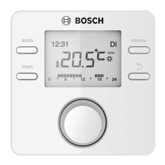
Product information CAUTION: The CR 50 user interface is a control unit without an outdoor CAUTION indicates a situation that could result in minor to temperature sensor. medium injury. Information on energy efficiency (ErP Directive) can be found in the operating instructions. -
Page 3: Temperature Sensor Characteristics
Additional accessories [1] User interface No other BUS modules and user interfaces are possible in the [2] Technical documentation system with the CR 50. Combination is not possible with the following products: Technical data • FR..., FW..., TR..., TF..., TA... -
Page 4: Electrical Connection
4 | Installation Installation ≥ 1000 6 mm 6 mm 3,5 mm 6 720 809 984-03.1O Fig. 4 Installation location in the reference room 3,5 mm 0 010 003 263-002 Fig. 5 Installation of the plinth Electrical connection Power is supplied to the user interface via the BUS cable. The wires are insensitive to polarity. - Page 5 Commissioning | 5 ▶ In the case of external inductive interferences (e.g. from Removing the user interface photovoltaic systems), use shielded cables (e.g. LIYCY) 1. Press the button on the underside of the plinth. and earth the shield on one side. Connect the shield to the 2.
-
Page 6: System Data Menu
System data menu In this menu, monitor and individually reconfigure the entire 0010005967-001 The CR 50 is now set up as a controller and the display system with respect to the automatic settings. automatically changes to the standard display. The heating... - Page 7 Service menu | 7 Frost protection Menu item Control range: Function description The setting by room temp offers sufficient frost protection Recirculation NO: The DHW circulation pump cannot be only if all the piping in the insulated building envelope is run in controlled by the heat source.
-
Page 8: Maintenance Menu
8 | Troubleshooting Menu item Possible values: Description Menu item Control range: Function description Appl.act.flow 20 ... 90 °C: Flow temperature measured at Fault history such as 2012-07-31 A02/816: The last 20 the heat source (actual temperature) faults are displayed, arranged in order of the time of occurrence. -
Page 9: Old Electrical And Electronic Appliances
Old electrical and electronic appliances | 9 A01 - 808 - [DHW heating: hot water temperature sensor A31 - 3021 - [Heating circuit flow temperature sensor 1 faulty - replacement mode active] faulty - standby mode active] Test procedure/cause Corrective measure Test procedure/cause Corrective measure Check the hot water... -
Page 10: Overview Of The Service Menu
10 | Overview of the service menu – Set room temp (desired room temperature) Overview of the service menu – Room Temp. (measured room temperature) The menu items are displayed in the sequence below. – DHW operation (DHW heating operation) –... - Page 12 Middle East and Caucasian Area Bosch Termoteknik Isıtma ve Klima Ticaret A.S. Aydınevler Mah. İnönü Cad. No:20 Küçükyalı Ofispark A Blok 34854 Küçükyalı / Maltepe - İSTANBUL Tel: +90 216 432 08 00 Products manufactured by Bosch Thermotechnik GmbH Junkersstrasse 20-24 D-73249 Wernau www.bosch-thermotechnology.com...
Need help?
Do you have a question about the CR 50 and is the answer not in the manual?
Questions and answers