Table of Contents
Advertisement
Quick Links
Advertisement
Table of Contents

Related Manuals for Void Stasys 4


Summary of Contents for Void Stasys 4
- Page 1 Stasys 4 User Guide V1.0...
- Page 2 This user guide is subject to change without notice. For the latest online version, visit: www.voidacoustics.com Void Acoustics and the Void logo are registered trademarks of Void Acoustics Research Ltd. in the United Kingdom, USA and other countries; all other Void trademarks are the property of Void Acoustics...
-
Page 3: Table Of Contents
5.12 Bias Q5 speakON wiring active mode System design System design principles Loudspeaker placement and positioning Mounting Installation safety Pole mounting Service Return Authorisation Shipping and packing consideration Appendix: Architectural specification Stasys 4 User Guide V1.0 Page 3... -
Page 4: Safety And Regulations
Void Acoustics Research Ltd for 1.2 Limitations reprocessing. For more information about where you can send your waste equipment for recycling, please contact Void Acoustics Research Ltd or one of your local distributors. -
Page 5: Limited Warranty
Stasys Series product (provided it was purchased at make the defective or malfunctioning product an Authorised Void Dealer) that it is free of defects available to Void free and clear of all liens or other in materials and workmanship and that each restrictions. -
Page 6: Unpacking And Checking
Stasys 4 loudspeakers come double boxed and are stapled shut; take care when unboxing and removing the staples to avoid injury or damage to the loudspeaker • If you need to place the Stasys 4 loudspeaker on a flat surface ensure you use a lint free product to protect the finish •... -
Page 7: Introduction
In buying this product, you are now part of the Void family and we hope using it brings you years of satisfaction. This guide will help you both use this product safely and ensure it performs to its full capability. -
Page 8: Stasys 4 Specifications
12 x M8 inserts Top hat Finish Textured polyurethane Grille Perforated steel with foam filter Measured in half space AES2 - 1984 compliant Calculated Figure 4.1: Horizontal directivity isobars Figure 4.2: Vertical directivity isobars Stasys 4 User Guide V1.0 Page 8... -
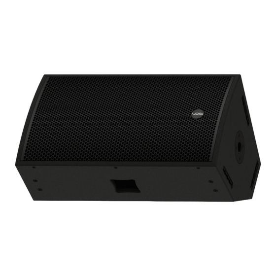
Page 9: Stasys 4 Dimensions
4 About 4.5 Stasys 4 dimensions (0.6”) (2.5”) 56.5 37.25 (2.2”) (1.5”) 81.5 (3.2”) (2.8”) 450 (17.7”) 430 (16.9”) 450 (17.7”) 160.5 160.5 (6.3”) (6.3”) 450 (17.7”) Figure 4.3: Dimensions Stasys 4 User Guide V1.0 Page 9... -
Page 10: Cabling And Wiring
30 m 15 m 5.3 Active/Passive mode switch Stasys 4 loudspeakers can be used in passive or active mode. The switch to change between these modes is located on the speakON panel on the rear of the loudspeaker as shown below. -
Page 11: Stasys 4 Wiring Diagram
HF Link Figure 5.3: Stasys 4 active mode wiring diagram Note: when using the Stasys 4 in passive mode be sure to only use 2 core cable as 4 core will cause the amplifier to overload. Stasys 4 User Guide V1.0... -
Page 12: Bias V3/V9 Speakon Tm Wiring Passive Mode
Output 1 Output 3 Output Left LF (15”) and HF (1.5”) Right LF (15”) and HF (1.5”) 2 (4 Ω load to amplifier) 2 (4 Ω load to amplifier) Max quantity per channel Stasys 4 User Guide V1.0 Page 12... -
Page 13: Bias Vq Speakon Tm Wiring Passive Mode
5.8 Bias Q5 speakON wiring passive mode Figure 5.9: Bias Q5 passive mode Bias Q5 Output 1 Output Left LF (15”) and HF (1.5”) 4 (2 Ω load to amplifier) Max quantity per channel Stasys 4 User Guide V1.0 Page 13... -
Page 14: Bias V3/V9 Speakon Tm Wiring Active Mode
Right LF (15”) Right HF (1.5”) 2 (4 Ω load to 2 (4 Ω load to 2 (4 Ω load to 2 (4 Ω load to Max quantity per channel amplifier) amplifier) amplifier) amplifier) Stasys 4 User Guide V1.0 Page 14... -
Page 15: Tm Wiring Active Mode
Figure 5.15: Bias Q5 active mode Bias Q5 Output 1 Output 2 Output LF (15”) HF (1.5”) 4 (2 Ω load to amplifier) 4 (2 Ω load to amplifier) Max quantity per channel Stasys 4 User Guide V1.0 Page 15... -
Page 16: System Design
6 System design 6.1 System design principles Stasys 4 are supplied in left and right-handed pairs, they can be arrayed as a single pair facing forward to provide a wide stereo image. Figure 6.1: Stasys 4 single pair arrangement The wedge shape of the Stasys 4 loudpseaker allows it to be used as a stage monitor. The enclosure has been design in such a way to allow it to be used in different position depending on the coverage required, as shown below. -
Page 17: Loudspeaker Placement And Positioning
6 System design 6.2 Loudspeaker placement and positioning When deploying Stasys 4, it is important to consider the speakers’ vertical position to maximise coverage in the vertical axis. Horizontal loudspeaker dispersion figures dictate the coverage of the loudspeaker, left to right, to the -3 dB points. - Page 18 Figure 6.5: Multi point loudspeaker arrangement In the horizontal plane rotate the Stasys 4 toward the audience area at an angle such that the centre line of the dispersion from each loudspeaker meets about two thirds of the way towards the rear of the audience area.
- Page 19 Avoid directing the Stasys 4 straight forward. This will result in a proportion of the power being directed towards the walls, creating possible reflective issues, as well as causing a gap in coverage at the centre of the audience area.
-
Page 20: Mounting
Do not use a telephone (even if hands-free) while rigging. Always concentrate fully on the rigging operation • Do not rig equipment that is worn, damaged, corroded, mishandled or over-stressed in any way • Use only Void-approved mounting equipment and accessories Stasys 4 User Guide V1.0 Page 20... -
Page 21: Pole Mounting
Stasys 4 loudspeaker into position. Figure 7.2: Loudspeaker positioning Step 2: Mount the Stasys 4 loudspeaker on the pole and rotate to the desired horizontal angle. Figure 7.3: Loudspeaker positioning Stasys 4 User Guide V1.0 Page 21... -
Page 22: Service
8.2 Shipping and packing considerations • When sending a Void Stasys 4 loudspeaker to an authorised service centre, please write a detailed description of the fault and list any other equipment used in conjunction with the faulty product. -
Page 23: Appendix: Architectural Specification
(W) 450 mm x (H) 750 mm x (D) 430 mm (17.7” x 29.6” x 16.9”). Weight shall be 38 kg (83.6 lbs). The loudspeaker shall be the Void Acoustics Stasys 4. Stasys 4 User Guide V1.0 Page 23... - Page 24 North America Void Acoustics North America 503-854-7134 sales.usa@voidacoustics.com Head Office Void Acoustics Research Ltd Unit 15 Dawkins Road Industrial Estate Poole Dorset BH15 4JY England +44 (0) 1202 666 006 info@voidacoustics.com Registered in England & Wales No. 07533536 www.voidacoustics.com...
Need help?
Do you have a question about the Stasys 4 and is the answer not in the manual?
Questions and answers