Vulcan-Hart V SERIES Service Manual
Hide thumbs
Also See for V SERIES:
- Service manual (20 pages) ,
- Service manual (17 pages) ,
- Service manual (16 pages)
Table of Contents
Advertisement
Quick Links
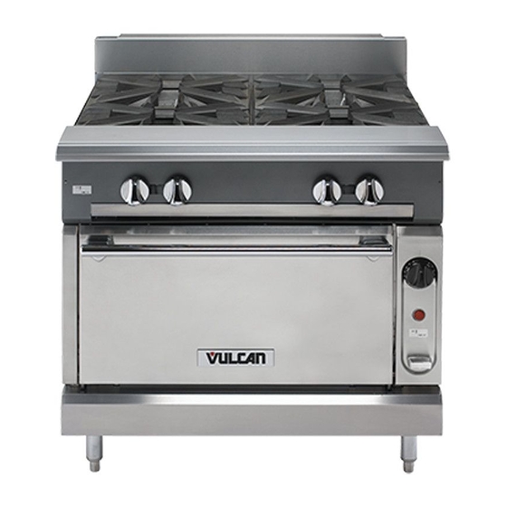
ONE POWERFUL PACKAGE
V SERIES HDR
GAS RANGES
TOPS
Open Top
Convection Oven
Hot Top
Griddle Top
Work Surface
For additional information on Vulcan- Hart or to locate an authorized parts and service
VULCAN-HART
DIVISION OF ITW FOOD EQUIPMENT GROUP, LLC
WWW.VULCANHART.COM
BASES
Standard Oven
Cabinet Base
This manual is prepared for use by trained service technicians and
should not be used by those not properly qualified. If you have
attended a service school for this product, you may still be qualified to
perform the procedures described in this manual. This manual is not
intended to be all encompassing. If you have not attended a service
school for this product, you should read, in its entirety, the repair
procedure you wish to perform to determine if you have the necessary
tools, instruments and skills required to perform the procedure.
Procedures for which you do not have the necessary tools,
instruments and skills should be performed by a trained service
technician.
provider in your area, visit our website at www.VulcanHart.com.
SERVICE MANUAL
- NOTICE -
3600 NORTH POINT BLVD.
BALTIMORE, MD 21222
F-37418 (12-09) Rev 2
Advertisement
Table of Contents

Subscribe to Our Youtube Channel
Related Manuals for Vulcan-Hart V SERIES


Summary of Contents for Vulcan-Hart V SERIES
-
Page 1: Convection Oven
SERVICE MANUAL ONE POWERFUL PACKAGE V SERIES HDR GAS RANGES BASES TOPS Standard Oven Open Top Convection Oven Hot Top Cabinet Base Griddle Top Work Surface - NOTICE - This manual is prepared for use by trained service technicians and should not be used by those not properly qualified. - Page 2 IMPORTANT FOR YOUR SAFETY THIS MANUAL HAS BEEN PREPARED FOR PERSONNEL QUALIFIED TO INSTALL GAS EQUIPMENT, WHO SHOULD PERFORM THE INITIAL FIELD START-UP AND ADJUSTMENTS OF THE EQUIPMENT COVERED BY THIS MANUAL. POST IN A PROMINENT LOCATION THE INSTRUCTIONS TO BE FOLLOWED IN THE EVENT THE SMELL OF GAS IS DETECTED.
-
Page 3: Table Of Contents
TABLE OF CONTENTS GENERAL Introduction Installation Operation Cleaning Lubrication Tools Specifications REMOVAL AND REPLACEMENT OF PARTS Electrical Lockout / Tagout Procedure Gas Lockout / Tagout Procedure Units Mounted On Casters Covers and Panels Manifold Cover Kick Panel Component Removal Oven Control Panel(S Model) Oven Control Panel (C Model) Pilot Safety Valve and temperature Control Assembly (S Model) Pilot Safety Valve (S Model) - Page 4 Top Burner Adjustment Oven Burner Adjustment Oven Door Microswitch Test Fan Control Switch Test (C Model) Convection Oven Motor Test (C Model) Solenoid Test (C Model) ELECTRICAL OPERATION Component Function Sequence of Operation Wiring Diagrams 120V C Model 208V C Model TROUBLESHOOTING Troubleshooting Chart CONDENSED SPARE PARTS LIST...
-
Page 5: General
GENERAL INTRODUCTION Procedures in this manual will apply to all models unless specified. Pictures and illustrations can be of any model unless the picture or illustration needs to be model-specific. Before performing maintenance on the equipment, thoroughly read this manual and carefully follow the instructions in the order given. -
Page 6: Removal And Replacement Of Parts
Gas Line Pressures Operating Pressures Natural - Recommended (in. W.C.) 6.0 Propane - Recommended (in. W.C.) 10.0 Incoming Pressure Natural - Recommended (in. W.C.) 7.0 min. Propane - Recommended (in. W.C.) 11.0 min REMOVAL AND REPLACEMENT OF PARTS ELECTRICAL LOCKOUT/TAGOUT Electrical Lockout/Tagout procedures are used to protect personnel working on an electrical appliance. -
Page 7: Gas Lockout / Tagout Procedure
GAS LOCKOUT/TAGOUT The Gas Lockout/Tagout procedure is used to protect personnel working on a gas appliance. Before performing any maintenance or service that requires gas disconnections, follow these steps: WARNING: All gas joints disturbed during servicing must be checked for leaks. Do not use an open flame. -
Page 8: Kick Panel
WARNING: Perform the GAS LOCKOUT/TAGOUT procedure before servicing the unit. 1. Perform the ELECTRICAL LOCKOUT/TAGOUT Procedure. 2. Rotate the yellow gas shut-off knob to the OFF position. Figure 1: Gas Shut-Off Valve Knob 3. Loosen the setscrew in the burner control knobs and remove the knobs. 4. -
Page 9: Component Removal
COMPONENT REMOVAL Oven Control Panel ( S Model) WARNING: Always perform the Electrical Lockout/Tagout procedure before removing any sheet metal panels or attempting to service this equipment. Failure to comply with this procedure can cause property damage, injury or death. WARNING: Perform the GAS LOCKOUT/TAGOUT procedure before servicing the unit. -
Page 10: Pilot Safety Valve And Temperature Control Assembly (S Model)
3. Rotate the yellow gas shut-off knob to the OFF position. Figure 6: Gas Shut-Off Valve Knob 4. Open the kick panel to gain access to the screw securing the control panel. 5. Loosen the setscrew from the yellow gas shut-off knob and remove the knob. 6. -
Page 11: Pilot Safety Valve (S Model)
5. Tag and disconnect the electrical connectors to the temperature control. 6. Remove the screws securing the gas mount bracket to the oven. 7. Remove the gas mount bracket, pilot safety valve and temperature control assembly from the oven. WARNING: All gas joints disturbed during servicing must be checked for leaks. Do not use an open flame. -
Page 12: Temperature Control (S Model)
8. Test the oven to verify proper operation. Figure 9: S Model Pilot Safety Valve Removal Temperature Control (S Model) WARNING: Always perform the Electrical Lockout/Tagout procedure before removing any sheet metal panels or attempting to service this equipment. Failure to comply with this procedure can cause property damage, injury or death. - Page 13 1. Perform the OVEN CONTROL PANEL removal procedure for the convection oven. 2. Tag and disconnect the electrical connectors from the top of the temperature control. 3. Remove the temperature control from the mount bracket. 4. Reverse the procedure to install the temperature control. 5.
-
Page 14: Solenoid (C Model)
Solenoid (C Model) WARNING: Always perform the Electrical Lockout/Tagout procedure before removing any sheet metal panels or attempting to service this equipment. Failure to comply with this procedure can cause property damage, injury or death. WARNING: Perform the GAS LOCKOUT/TAGOUT procedure before servicing the unit. 1. -
Page 15: Manual Gas Shut-Off Valve (C Model)
4. Remove the pipe nipple and manual gas shut-off valve from the pilot safety valve. 5. Remove any residual tape from the pipe nipples and fittings and coat the threads with new gas-rated (yellow) Teflon tape. WARNING: All gas joints disturbed during servicing must be checked for leaks. Do not use an open flame. -
Page 16: Oven Pilot Assembly
Figure 15: C Model Shut-Off Valve Removal Oven Pilot Assembly WARNING: Always perform the Electrical Lockout/Tagout procedure before removing any sheet metal panels or attempting to service this equipment. Failure to comply with this procedure can cause property damage, injury or death. WARNING: Perform the GAS LOCKOUT/TAGOUT procedure before servicing the unit. -
Page 17: Oven Burner Assembly
Oven Burner Assembly WARNING: Always perform the Electrical Lockout/Tagout procedure before removing any sheet metal panels or attempting to service this equipment. Failure to comply with this procedure can cause property damage, injury or death. WARNING: Perform the GAS LOCKOUT/TAGOUT procedure before servicing the unit. 1. -
Page 18: Pilot Quick Disconnect Valve
Figure 19: Oven Burner Nozzle and Gas Orifice Removal Pilot Quick Disconnect Valve NOTE: The pilot quick disconnect valve is mounted to the gas manifold behind the manifold cover. WARNING: Always perform the Electrical Lockout/Tagout procedure before removing any sheet metal panels or attempting to service this equipment. Failure to comply with this procedure can cause property damage, injury or death. -
Page 19: Top Section Burner (Char Broiler)
3. Remove the bowl deflector. 4. Remove the burner heads. 5. Disconnect the burner tubes from the pilot coupler. 6. To remove the burner, lift the rear of the burner, slide the burner back and lift to disengage it from the burner control valves. 7. -
Page 20: Top Section Burner (French/Hot Top And Griddle)
8. Reverse the procedure to install the top section burner. 9. Test the oven to verify proper operation. Figure 22: Char Broiler Top Burner Removal Top Section Burner (French/Hot Top/Griddle) WARNING: Always perform the Electrical Lockout/Tagout procedure before removing any sheet metal panels or attempting to service this equipment. Failure to comply with this procedure can cause property damage, injury or death. -
Page 21: Top Section Burner Valve
Top Section Burner Control Valve WARNING: Always perform the Electrical Lockout/Tagout procedure before removing any sheet metal panels or attempting to service this equipment. Failure to comply with this procedure can cause property damage, injury or death. WARNING: Perform the GAS LOCKOUT/TAGOUT procedure before servicing the unit. 1. -
Page 22: Convection Motor (C Model)
5. Test the oven to verify proper operation. Figure 25: Convection Motor Fan Control Switch Removal Convection Motor (C Model) WARNING: Always perform the Electrical Lockout/Tagout procedure before removing any sheet metal panels or attempting to service this equipment. Failure to comply with this procedure can cause property damage, injury or death. -
Page 23: Oven Door Microswitch (C Model)
Oven Door Microswitch (C Model) WARNING: Always perform the Electrical Lockout/Tagout procedure before removing any sheet metal panels or attempting to service this equipment. Failure to comply with this procedure can cause property damage, injury or death. 1. Perform the CONTROL PANEL removal procedure for the convection oven. 2. -
Page 24: Gas Leak Check
Gas Leak Check WARNING: All gas joints disturbed during servicing must be checked for leaks. Do not use an open flame. Use a hazardous gas tester or a soap and water solution (Bubbles indicate a gas leak). Failure to comply can cause property damage, injury or death. WARNING: If a gas leak is detected, do not operate this or any other equipment until the leak has been properly repaired. -
Page 25: Gas Pressure Regulator Adjustment
WARNING: All gas joints disturbed during servicing must be checked for leaks. Do not use an open flame. Use a hazardous gas tester or a soap and water solution (Bubbles indicate a gas leak). Failure to comply can cause property damage, injury or death. -
Page 26: Oven Pilot Flame Check And Adjustment
propane. e. Repeat step 6a & 6b. If pressure drop is still greater than 1/2" W.C., there may be a lack of volume due to too small of a supply line. Check with the gas provider about installing a larger size gas line. -
Page 27: Oven Burner Nozzle And Gas Orifice Check
Oven Burner Nozzle and Gas Orifice Check The oven burner nozzle is mounted between the oven gas manifold and the u-burner assembly. If burner operation seems poor and other systems have been checked, remove the burner nozzle and check for blockage or damage as follows: WARNING: Always perform the Electrical Lockout/Tagout procedure before removing any sheet metal panels or attempting to service this equipment. - Page 28 2. If this does not solve the problem, check the burner for obstructions and clear as necessary. If the flame is lifting off the burner: There is too much primary air. Close the air shutter slightly and retest. NOTE: If the grates, hot tops or oven bottoms have been removed, recheck flame adjustments with these items in place.
- Page 29 Oven Door Microswitch Test (C Model) The oven door microswitch lever should be depressed when the oven door is closed. WARNING: Always perform the Electrical Lockout/Tagout procedure before removing any sheet metal panels or attempting to service this equipment. Failure to comply with this procedure can cause property damage, injury or death.
- Page 30 4. Place the fan control switch in the ON position. Verify continuity is present between the contacts for wires 62 & 13 and wires 63 & 64. Verify there is no continuity between wires 63 & 61. 5. Place the fan control switch in the COOL DOWN position. Verify continuity is present between the contacts for wires 63 &...
- Page 31 WARNING: Always perform the Electrical Lockout/Tagout procedure before removing any sheet metal panels or attempting to service this equipment. Failure to comply with this procedure can cause property damage, injury or death. WARNING: Perform the GAS LOCKOUT/TAGOUT procedure before servicing the unit. 1.
- Page 32 ELECTRICAL OPERATION Component Function Power Cord A three-prong grounding plug that connects the oven to the electrical power source. The oven will not operate unless it is connected to an electrical power supply. Convection Oven Solenoid The solenoid is a normally closed switch that opens and closes the gas valve. When the electrical circuit is completed through the solenoids coil, a magnetic field is created, drawing on a spring-loaded plunger which opens the gas valve.
- Page 33 control switch is placed in the ON position. The convection motor should shut off when the oven door is opened unless the fan control switch is placed to the COOL DOWN position. In the COOL DOWN position the oven door microswitch is bypassed so that the convection motor will run while the oven door is open to rapidly lower the oven temperature.
- Page 34 thermostat and the solenoid. iii. The solenoid will close the gas valve and shutoff gas to the burner. iv. Pilot remains lit. 5. Fan control switch to OFF. A. Power is removed from one side of the convection motor. i. The centrifugal switch will open and power will be removed from the solenoid and the thermostat.
-
Page 35: Troubleshooting
TROUBLESHOOTING SYMPTOM POSSIBLE CAUSES 1. Low gas pressure. Pilot does not remain lit. 2. Thermocouple not positioned correctly or malfunctioning. 3. Control valve malfunction. 1. Orifice incorrect size or obstructed. 2. Air Shutter not adjusted correctly. Burner flame too yellow 3. - Page 36 CONDENSED SPARE PARTS LIST PART NO. DESCRIPTION 00-411496-000B1 Rocker Switch 00-411496-000F1 Door Switch 00-405016-00001 Cord, Supply Electric 00-957367-00001 Burner Valve 00-499712-00001 Burner Valve Knob 00-497765-00001 Pilot Quick Disconnect Valve 00-499970-00001 HD Quick Disconnect Pilot Valve 00-404060-00001 Air Shutter (Top Burner) 00-719329- Air Shutter (Broiler) 00-428045-00001...
Need help?
Do you have a question about the V SERIES and is the answer not in the manual?
Questions and answers