Table of Contents
Advertisement
This Manual is prepared for the use of trained Vulcan Service
Technicians and should not be used by those not properly
qualified.
This manual is not intended to be all encompassing. If you have
not attended a Vulcan Service School for this product, you should
read, in its entirety, the repair procedure you wish to perform to
determine if you have the necessary tools, instruments and skills
required to perform the procedure. Procedures for which you do
not have the necessary tools, instruments and skills should be
performed by a trained Vulcan Service Technician.
The reproduction, transfer, sale or other use of this Manual,
without the express written consent of Vulcan, is prohibited.
This manual has been provided to you by ITW Food Equipment
Group LLC ("ITW FEG") without charge and remains the property
of ITW FEG, and by accepting this manual you agree that you will
return it to ITW FEG promptly upon its request for such return at
any time in the future.
A product of Vulcan-Hart
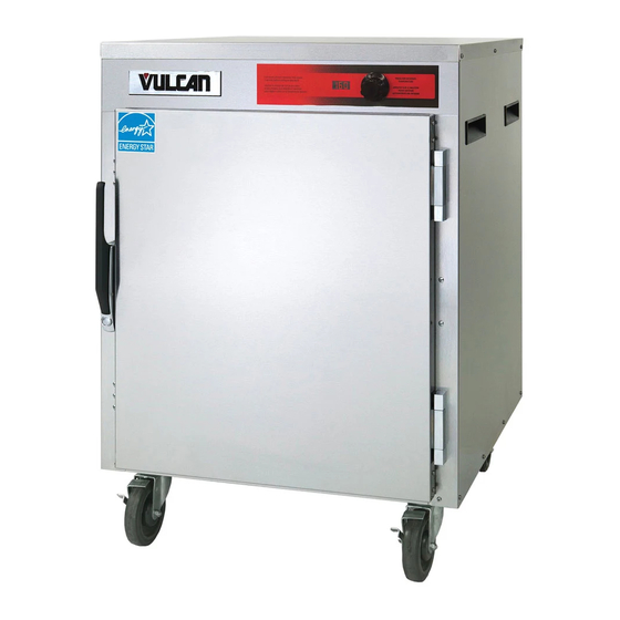
SERVICE MANUAL
V Series Heated Holding
Insulated Cabinets
VBP5
VBP7
VBP13
VBP15
VBP18
VHP7
VHP15
VPT7
VPT13
VPT15
VPT18
- NOTICE -
3600 North Point Blvd Baltimore, MD 21222
ML-138030
ML-126358
ML-126359
ML-126360
ML-126344
ML-126346
F45748 (0219)
Advertisement
Table of Contents

Related Manuals for Vulcan-Hart VBP5


Summary of Contents for Vulcan-Hart VBP5
- Page 1 ITW FEG, and by accepting this manual you agree that you will return it to ITW FEG promptly upon its request for such return at any time in the future. A product of Vulcan-Hart 3600 North Point Blvd Baltimore, MD 21222 F45748 (0219)
-
Page 2: Table Of Contents
V Series Heated Holding Insulated Cabinets TABLE OF CONTENTS SERVICE UPDATES ..................3 SERVICE UPDATES . -
Page 3: Service Updates
V Series Heated Holding Insulated Cabinets - SERVICE UPDATES SERVICE UPDATES SERVICE UPDATES JANUARY 2019 • New service manual release. TIS DOCUMENT LIST - V SERIES HEATED HOLDING INSULATED CABINETS SERVICE TAB Document Title Document Type V Series Heated Holding Transportation Cabinets Service Manual SERVICE MULTIMEDIA TAB Document Title... -
Page 4: General
V Series Heated Holding Insulated Cabinets - GENERAL GENERAL INTRODUCTION DATA PLATE LOCATIONS This manual is applicable only to models listed on the cover page. Procedures in this manual will apply to all models unless specified. Pictures and illustrations can be of any model unless they need to be model specific. -
Page 5: Removal And Replacement Of Parts
V Series Heated Holding Insulated Cabinets - REMOVAL AND REPLACEMENT OF PARTS REMOVAL AND REPLACEMENT OF PARTS Remove insulation (1, Fig. 5). TOP COVER Disconnect the electrical power to the machine and follow lockout / tagout procedures. NOTE: Remove top cover to access power cord, cooling fan, and control board. -
Page 6: Heating Elements
V Series Heated Holding Insulated Cabinets - REMOVAL AND REPLACEMENT OF PARTS When installing inside access cover, verify edge inserts into slot without catching. Fig. 7 Reverse procedure to install. Fig. 9 Verify air flow direction in cavity. HEATING ELEMENTS Disconnect the electrical power to the machine and follow lockout / tagout procedures. -
Page 7: Power Cord
V Series Heated Holding Insulated Cabinets - REMOVAL AND REPLACEMENT OF PARTS When installing inside access cover, verify edge inserts into slot without catching. Fig. 13 POWER CORD Fig. 11 Disconnect the electrical power to Remove heating element mounting screws. the machine and follow lockout / tagout procedures. -
Page 8: High Limit Switch
V Series Heated Holding Insulated Cabinets - REMOVAL AND REPLACEMENT OF PARTS HIGH LIMIT SWITCH Disconnect the electrical power to the machine and follow lockout / tagout procedures. Remove TOP COVER . Note and disconnect wiring. Remove mounting screws for high limit switch (1, Fig. -
Page 9: Component Cooling Fan
V Series Heated Holding Insulated Cabinets - REMOVAL AND REPLACEMENT OF PARTS Note air flow direction on fan when replacing fan. (1, Rotation Fig. 20) (2, Air Flow Fig. 20) Fig. 18 Reverse procedure to install. COMPONENT COOLING FAN Disconnect the electrical power to the machine and follow lockout / tagout procedures. - Page 10 V Series Heated Holding Insulated Cabinets - REMOVAL AND REPLACEMENT OF PARTS Fig. 21 Remove "optional" knob cover if applicable (VBP5 and VBP7). Fig. 24 Remove potentiometer retaining nut. Fig. 22 Remove retaining screw in knob. Fig. 25 Remove control board mounting nuts.
-
Page 11: Door Gasket
V Series Heated Holding Insulated Cabinets - REMOVAL AND REPLACEMENT OF PARTS DOOR GASKET NOTE: Measure gasket before ordering replacement. Gasket is a separate component from retainer and should be ordered separately from retainer. Open door. Unscrew gasket retainers. Fig. 29 Install retainer with flat side against cavity wall and channel toward inside of cabinet. -
Page 12: Door Latch (Magnetic)
V Series Heated Holding Insulated Cabinets - REMOVAL AND REPLACEMENT OF PARTS Fig. 31 Remove door hinge inside mounting screws from upper door hinge while supporting door weight. Lift door assembly from cabinet. Reverse procedure to install. Fig. 32 Check for proper operation. DOOR LATCH (MAGNETIC) NOTE: Note orientation of door handle before removal. - Page 13 V Series Heated Holding Insulated Cabinets - REMOVAL AND REPLACEMENT OF PARTS Install handle in the same orientation it was removed. Check for proper operation. Fig. 33 Open door. Remove screws securing door latch to door assembly. Fig. 34 Reverse procedure to install. Page 13 of 17 F45748 (0219)
-
Page 14: Service Procedures And Adjustments
V Series Heated Holding Insulated Cabinets - SERVICE PROCEDURES AND ADJUSTMENTS SERVICE PROCEDURES AND ADJUSTMENTS Heating Elements TEMPERATURE VERIFICATION Model Wattage Voltage Resistance all VBP 1500 38.4 +/- 10 % The warmer and its parts are hot. Use care when NOTE: If numbers do not match, replace HEATER operating, cleaning or servicing the oven. -
Page 15: Electrical Operation
V Series Heated Holding Insulated Cabinets - ELECTRICAL OPERATION ELECTRICAL OPERATION COMPONENT DESCRIPTIONS ITEM DESCRIPTION Food Compartment Fan Circulates air inside the cabinet. Moisture resistant with metal fan blades. Controller Board Controls the temperature, humidity and fan inside the cabinet. Heating Element - Dry Heats the air to keep prepared food at the proper serving temperatures. -
Page 16: Wiring Diagram
V Series Heated Holding Insulated Cabinets - ELECTRICAL OPERATION WIRING DIAGRAM Fig. 35 Fan relay K2 is energized, K2 contacts close and SEQUENCE OF OPERATION power the fans. Based on temperature and humidity settings, the Conditions. board determines whether K1 relay will be Unit connected to correct voltage and is energized to power element. -
Page 17: Troubleshooting
V Series Heated Holding Insulated Cabinets - ELECTRICAL OPERATION TROUBLESHOOTING Symptom Possible Cause Cabinet not connected to power source or circuit breaker tripped. Cabinet not operating. Cabinet lighted power switch not ON or malfunctioning. Shorted heating element. Ground Fault Circuit Indicator (GFCI) Pinched/damaged wiring (heating elements or fan).
Need help?
Do you have a question about the VBP5 and is the answer not in the manual?
Questions and answers