Siemens MICROMASTER 420 Getting Started Manual
Hide thumbs
Also See for MICROMASTER 420:
- Operating instructions manual (190 pages) ,
- Operating instruction (130 pages) ,
- Reference manual (94 pages)
Table of Contents
Advertisement
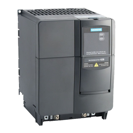
MICROMASTER 420
Getting Started Guide
This Getting Started Guide allows easy and efficient commissioning of the
MICROMASTER 420 inverter. For further technical information, please refer to
the Operating Instructions and the Reference Manual on the CD-ROM
supplied with the MICROMASTER 420 inverter.
Contents
1
2
3
4
5
6
7
8
Getting Started Guide - September 2000
6SE6400-5AB00-0BP0
English
3
4
5
6
6
7
7
8
9
10
10
11
11
11
11
11
12
12
13
13
13
14
15
1
Advertisement
Table of Contents

Related Manuals for Siemens MICROMASTER 420


Summary of Contents for Siemens MICROMASTER 420
-
Page 1: Table Of Contents
Getting Started Guide This Getting Started Guide allows easy and efficient commissioning of the MICROMASTER 420 inverter. For further technical information, please refer to the Operating Instructions and the Reference Manual on the CD-ROM supplied with the MICROMASTER 420 inverter. -
Page 2: Micromaster
Please read the information carefully, since it is provided for your personal safety and will also help prolong the service life of your MICROMASTER 420 inverter and the equipment you connect to it. -
Page 3: Mechanical Installation
To ensure the safe operation of the inverter, it must be installed and commissioned by qualified personnel in full compliance with the warnings laid down in the MICROMASTER 420 operating instructions. Take particular note of the general and regional installation and safety regulations regarding work on dangerous voltage installations (e.g. -
Page 4: Electrical Installation
Electrical Installation Warning Before electrical installation, set the power supply frequency for Europe or North America. For operation on the North American Power Supply, set the DIP-Switch (2) to 60 Hz (up). For operation on the European Power Supply, leave the DIP-Switch (2) in the default position 50 Hz (down). -
Page 5: Avoiding Electro-Magnetic Interference
Avoiding Electro-Magnetic Interference The inverters are designed to operate in an industrial environment where a high level of EMI can be expected. Usually, good installation practices will ensure safe and trouble-free operation. If you encounter problems, follow the guidelines stated below. Actions to Take Ensure that all equipment in the cubicle is well grounded using short, thick grounding cable connected to a common star point or busbar... -
Page 6: Commissioning The Micromaster 420 Inverter
The motor rating data, Voltage, Current and Frequency are all compatable with the inverter data. (A standard Siemens motor is recommended). Linear V/f motor speed, controlled by an analogue potentiometer. Maximum speed 3000 min -1 with 50 Hz (3600 min -1 with 60 Hz), Controllable using a potentiometer via the inverter’s analogue inputs... -
Page 7: Commissioning With Getting Started Guide
ON / OFF switch The ‘BOP’ Commissioning with the Status Display Panel When commissioning the MICROMASTER 420 with the Status Display Panel (SDP), the drive application must be covered by the default settings of your MICROMASTER 420. Connect On/Off Switch to the terminals 5 and 8... -
Page 8: Commissioning With The Basic Operator Panel
To change the frequency setpoint via the BOP set P1000 =1 (when P0700 = 1). Functions This button can be used to view additional information. See Section 5.1.2 on page 42 of the MICROMASTER 420 Operating Instructions. Getting Started Guide – September 2000 6SE6400-5AB00-0BP0... -
Page 9: Changing Parameters And Settings Using A 'Bop' / 'Aop
Changing parameters and settings using a ‘BOP’ / ‘AOP’ The following description shows how to change the parameter P1082. Use this description as a guide for setting any parameters using the ‘BOP’. Step Result on display ♦ H P(1) Press to access parameters 2 P(1) -
Page 10: Quick Commissioning
Quick Commissioning The following parameters must be followed through in their entirety to ensure optimised and efficient operation of the inverter. Please note that P0010 must be set to ‘1 = Quick Commissioning’ to allow this procedure to be carried out. For information on how to change parameter settings, please refer to section 4.5 of this guide. -
Page 11: Motor Data For "Quick Commissioning
Speed, frequency, motor direction and current values etc displayed Capacity to store and download up to 10 parameter sets Additional Control Applications The MICROMASTER 420 can also be controlled by the following means: Digital inputs / Analogue inputs Serial Link via USS Protocol Automated system via PROFIBUS connection Further information ... -
Page 12: Changing The Display / Operator Panel
Changing the Display / Operator Panel The procedure for changing the operator panel is illustrated below. Changing single digits in Parameter values For changing the parameter value rapidly, the single digits of the display can be changed by performing the following actions: Ensure you are in the parameter value changing level (see "Changing parameters with BOP"). -
Page 13: Troubleshooting
It is possible that the motors’ performance may be affected at low frequencies if parameter P1310 falls under 50 (default value). For further fault code designations, please refer to the MICROMASTER 420 Operating Instructions on the CD included with the inverter. -
Page 14: Parameterization Of The Inverter Overview
Parameterization of the Inverter Overview Prerequisites: Mechanical and electrical Installation are completed. Setting the supply frequency DIP Switch 2: Off = 50 Hz / ON = 60 Hz Power ON Quick Commissioning P0010 = 1 See Chapter 5. For a lot of applications the inverter will be ready. -
Page 15: Parameter Structure
Parameter Structure Overall Structure Example Inverter Unit (no filter function) allows direct access to the parameters depending on the selected access level P0004 = 22 P0004 = 2 PI Controller Inverter Unit P0004 = 21 P0004 = 3 Alarms, Warnings & Motor Data Monitoring P0004 = 7... - Page 16 5B33 for use in a pollution degree 2 ISO 9001 Siemens plc operates a quality management system, which complies with the requirements of ISO 9001. To submit any suggestions for improvements, please visit the Siemens Standard Drives Web Site at http://www.siemens.de/micromaster *6SE6400-5AB00-0BP0* Siemens plc Automation &...
Need help?
Do you have a question about the MICROMASTER 420 and is the answer not in the manual?
Questions and answers