Table of Contents
Advertisement
Quick Links
RV
Read this manual before installing or using this product. Failure to follow the instructions
and safety precautions in this manual can result in personal injury and/or cause the
product to not operate properly.
LED Lighting
These instructions apply to OEM and Aftermarket Installations. Details and procedures
unique to a specific application are labeled appropriately.
052568-001r5
E
CLIPSE
T
HIS PUBLICATION COVERS MODELS
Universal Eclipse
Printed in USA
I
NSTALLATION
A
RMS AND
:
w/ Single Switch or Direct Response Electronics
Adjustable Pitch
M
ANUAL
C
ANOPY
E0069
August, 2017
Advertisement
Table of Contents

Subscribe to Our Youtube Channel
Related Manuals for Carefree Universal Eclipse


Summary of Contents for Carefree Universal Eclipse
- Page 1 ANOPY HIS PUBLICATION COVERS MODELS Universal Eclipse w/ Single Switch or Direct Response Electronics Read this manual before installing or using this product. Failure to follow the instructions and safety precautions in this manual can result in personal injury and/or cause the product to not operate properly.
-
Page 2: Table Of Contents
ABLE OF ONTENTS Product Overview .......................... 1 Eclipse Patio Awning Specifications: ....................1 Eclipse Patio Awning Options: ....................... 1 Component Checklist..........................2 Installation ............................. 4 Required Pre-Installation Preparation ..................... 4 Installing an Awning Rail ......................... 4 Assembling the Awning .......................... 5 Mounting the Awning .......................... -
Page 3: General Safety
ROPRIETARY TATEMENT The Eclipse Patio Awning is a product of Carefree of Colorado, located in Broomfield, Colorado, USA. The information contained in or disclosed in this document is considered proprietary to Carefree of Colorado. Every effort has been made to ensure that the information presented in the document is accurate and complete. -
Page 5: Product Overview
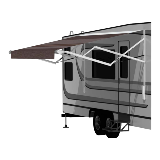
Installation Manual Carefree of Colorado CLIPSE RODUCT VERVIEW The unique "scissor" style arms eliminate the need for vertical ground supports. Easy to use 6 position pitch adjustment. The pitch can be left in any position and the Eclipse will roll up completely! When the awning is rolled back out, it rolls out to the pitch setting previously set. -
Page 6: Component Checklist
Installation Manual CLIPSE Carefree of Colorado OMPONENT HECKLIST Roller Tube Single Switch (Standard) Arms Common Hardware Direct Response (Optional) Carefree of Colorado 12V DIRECT RESPONSE RR433 CONTROL BOX (Optional) PART NO. 060574-003 MOTION SENSITIVITY SWITCH +12V PATIO SWITCH GROUND MOTION SENSOR... - Page 7 Installation Manual Carefree of Colorado CLIPSE I ESCRIPTION Rollbar Assembly Screw, HWHC #6 x 3/8 Tractioner Screw, Truss Head, SQ Drive #10 x 5/8 LH Arm Assy, Idler RH Arm Assy, Motorized ...
-
Page 8: Installation
Installation Manual CLIPSE Carefree of Colorado NSTALLATION EQUIRED NSTALLATION REPARATION 1. Park the vehicle on a flat surface and level the unit. 2. If this is an upgrade for a manual patio awning, follow the awning manufacturer's instructions and remove the awning from the coach including the roll bar and canopy. -
Page 9: Assembling The Awning
Installation Manual Carefree of Colorado CLIPSE SSEMBLING THE WNING 1. Decide on the location of the switches and control box to determine the cable routing. 2. If the motor and Direct Response sensor cables are to be routed through the RV wall at the bottom of the arm, no modification is required. -
Page 10: Mounting The Awning
Installation Manual CLIPSE Carefree of Colorado OUNTING THE WNING CAUTION It is recommended that at least three people install the awning due to its size and weight. NOTE: For the bottom 3 mounting holes: if mounting into structure, use the 1/4 x 1 1/2 screws; if not attaching into structure, use the moly rivets. - Page 11 Installation Manual Carefree of Colorado CLIPSE 9. Confirm that the arm is perpendicular to the awning rail, repeat step 9 and attach the arm at the second mounting point (shown in Figure 6). 10. Position the roller assembly so that it is perpendicular to the motorized arm assembly. Position the non-motorized arm perpendicular to the roller assembly.
-
Page 12: Electrical
Installation Manual CLIPSE Carefree of Colorado LECTRICAL WARNING Shock Hazard. Always disconnect battery or power source before working on or around the electrical system. Notes: 1. Failure to follow the wiring instructions in this publication may void the motor warranty. - Page 13 Installation Manual Carefree of Colorado CLIPSE 7. Route the awning motor wires through the switch hole and attach to the switch connector: To +12VDC BLACK To Ground BLUE RED Motor Wire RED Motor Wire WHITE BLACK Motor Wire WHITE BLACK Motor Wire...
-
Page 14: Direct Response Installation
Installation Manual CLIPSE Carefree of Colorado IRECT ESPONSE NSTALLATION Direct Response is available as a factory installed option for OEM's. For aftermarket installations, the Direct Response system is available as an upgrade kit SR0036. Routing the Wire into the Vehicle 1. -
Page 15: Wiring An Additional Patio Switch
Installation Manual Carefree of Colorado CLIPSE Wiring an Additional Patio Switch This section is for wiring an additional P switch. ATIO (refer to the wiring diagram on page 13) Route the switch wires to the main switch location. Splice the wires in parallel with the E switch wires. -
Page 16: Installing The Remote Receiver
Installation Manual CLIPSE Carefree of Colorado Installing the Remote Receiver Determine the location of the optional RF receiver: 1.1 Do not mount the unit near heat producing elements such as LP appliances or engine exhaust components. 1.2 For best reception, do not mount the unit near or on a metal surface. -
Page 17: Wiring Diagram - Direct Response
Installation Manual Carefree of Colorado CLIPSE Wiring Diagram - Direct Response Ignition Switched +12VDC Ignition Version_______ Lockout 12VDC Sensor Ground (Optional) Splitter Extend/ Retract Motion On/Off Black Blue Control Carefree of Colorado Carefree of Colorado 12V DIRECT RESPONSE 12V DIRECT RESPONSE... -
Page 18: Ignition Lockout Sensor Installation (Optional)
Installation Manual CLIPSE Carefree of Colorado Ignition Lockout Sensor Installation (Optional) The optional STD ignition lockout will disable the extend function when the module receives a current through a switched 12VDC circuit. A switched 12VDC source is a line that is "hot" when the ignition switch is in the on position; or, a 12VDC circuit through a relay that is "hot"... -
Page 19: Final Assembly
Installation Manual Carefree of Colorado CLIPSE INAL SSEMBLY TTACHING THE ASCIA AND OTTOM OVER Make sure the awning is completely closed. Facia Tab Insert the tab, on the fascia, under the arm base and rest it on the mounting plate. -
Page 20: Removing The Temporary Assembly Pins
Installation Manual CLIPSE Carefree of Colorado EMOVING THE EMPORARY SSEMBLY 2 pins are inserted into the back of the left (idler) head for lateral stability during installation. Using a pair of pliers, remove and discard both pins. NOTE: The awning will operate with the pins in place; for long term use, the pins must be removed to allow for climate variances. -
Page 21: Optional Led's
Installation Manual Carefree of Colorado CLIPSE LED’ PTIONAL Optional White LED light strips mounted in the roller tube are available for aftermarket and OEM installations. Some OEM’s may offer LEDs at the awning rail. NOTICES: a. Do not route the wire over sharp edges or heat sources that can cut or fray the wires or wire insulation. -
Page 22: Switch Installation
Installation Manual CLIPSE Carefree of Colorado WITCH NSTALLATION A single pole switch is required for the white LED installations. For optional OEM RGB installations the single pole switch can be used as an optional power on/off control. This allows the lights to be shut off if the awning is retracted with the lights on. -
Page 23: Power Connection For Optional Oem Rgb Led's
Installation Manual Carefree of Colorado CLIPSE OEM RGB LED' OWER ONNECTION FOR OPTIONAL The RGB LED uses a receiver and remote (SR0109). NOTE: The installation requires that the power line (+12VDC) be attached to a dedicated 2A circuit breaker or a 2A in-line fuse must be installed between the control module and power source. Locate the fuse for easy access.
Need help?
Do you have a question about the Universal Eclipse and is the answer not in the manual?
Questions and answers