Table of Contents
Advertisement
(Please read carefully
before use)
Before installing and using this
machine, you must read this user
guide carefully. Keep it in a safe
place, in case you need to refer to
User manual
it later.
This manual should not be used
without the CN 97 program manual
IS400 machine
- B2241 701.
First contact
D2083 701 - 02.2008 - ENG - (UPDATED EDITION NUMBER: 10)
Advertisement
Table of Contents

Subscribe to Our Youtube Channel
Related Manuals for GRAVOGRAPH IS400


Summary of Contents for GRAVOGRAPH IS400
-
Page 1: User Manual
User manual it later. This manual should not be used without the CN 97 program manual IS400 machine - B2241 701. First contact D2083 701 - 02.2008 - ENG - (UPDATED EDITION NUMBER: 10) - Page 2 Gravograph to notify anybody of such revision or changes. Gravograph can not be held liable for any problems arising out of the application or use of any products, circuits, or software described herein. Neither does it convey a license under its patent rights nor the patent rights of third parties.
-
Page 3: Table Of Contents
Physical installation advice ......................14 Electric installation advice ......................15 Electrical connections of the machine ....................16 Connecting the IS400 machine to a PC ................... 17 Switching the machine on ......................20 Problems ............................. 20 Switching the machine off ......................20 Mechanical block .......................... -
Page 4: Information About Regulations
• "Low voltage" Directive 2006/95/EC The modification or transformation of this equipment, the adaptation and installation of accessories not recommended by GRAVOGRAPH, the installation of this equipment in a manufacturing process, the piloting by a robot, the connection to an external automaton, modify the characteristics of this material and can make it not compliant with the European Directives it is subjected. -
Page 5: Presentation
• Do not place any object on the machine other than that to be engraved. • The machine should never be used with anything other than Gravograph accessories and tools. • Never hold the material to be engraved in your hands. Only use the GRAVOGRAPH clamping systems designed for your machine. -
Page 6: Stages Of Unpacking
Stages of unpacking Two people are necessary to unpack the IS400 machine. Before opening the cardboard box, check that it is the right way up. After opening the box (pict. 1): Take out the documents. Take off the protective packaging Take out the tool box. -
Page 7: Unpacking - Contents Of Package
Unpacking - Contents of package Check the condition of the packaging when you receive it. If there are any signs of damage, inform the carrier and your GRAVOGRAPH dealer immediately by recorded delivery, specifying the exact nature of the problem. - Page 8 D2. a spindle belt D3. a cutter knob D4. a short allen key D5. a round allen key D6. a brush D7. a key D8. a screwdriver (3,5) D9. a pair of standards jigs First contact IS400 machine . 8...
-
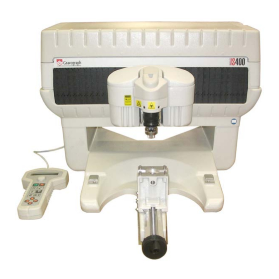
Page 9: Description
IS400 machine. The actual engraving process is controlled by the spindle. The object to be engraved is held in the vice (as standard) or by any other system recommended by GRAVOGRAPH (consult your GRAVOGRAPH dealer for more information on systems available). - Page 10 Index finger Scaled knob Nose nut Auto ZRef switch J10. LASER diode CAUTION - LASER RADIATION Do not stare into beam LASER diode - Wavelength: 630-680nm - Max. Output < 1mW CLASS 2 LASER PRODUCT IS400 machine . 10 First contact...
-
Page 11: Vice
Vice The vice holds the material to be engraved (pict 6). The IS400 machine is supplied with a pair of jigs (G) which should be mounted onto the vice. Open the jaws (L2) by turning the tightening knob (L3) anti-clockwise. -
Page 12: Long Plate Support Kit
Long plate support kit IS400 machine . 12 First contact... -
Page 13: Rear View Of The Machine
The machine must always be switched off before connecting or disconnecting a cable, the cylinder attachment and the pen attachment (optional accessories), as indicated on label displayed on the back of the electronic box and of the machine : First contact IS400 machine . 13... -
Page 14: Installing
Physical installation advice • Put the Gravograph machine onto a stable flat, clean surface with mini. sizes of 520x500 mm. Make sure the back of the machine is well-ventilated, do not put it too close to anything (wall, other machines etc). -
Page 15: Electric Installation Advice
In order to avoid outside interference, the user is advised to carry out the following points. • Plug the Gravograph machine into a mains line, avoiding having several machines on the same line (several plugs on the same line or using a multi-plug). -
Page 16: Electrical Connections Of The Machine
(N5) (for the Automaton function) are also present at the back of the machine. Liaison boitier électronique/machine Tourne Cylindre Broche externe E/S Standard Electronics-machine connection Cylinder attachment External Spindle Standard I/O Verbindung Elektronikeinheit/Maschine Abrollvorrichtung Externe Spindel E/A Standard IS400 machine . 16 First contact... -
Page 17: Connecting The Is400 Machine To A Pc
• Separate the mains cable and the transmission cable (avoid connecting the transmission and mains cables to the same socket, etc ...). Follow the connection procedure depending on the transmission cable supplied with the IS400. The machine is delivered with the following cables : •... - Page 18 PC/IS400 connection using the USB port Plug the USB cable into the USB (N8) port of the IS400 machine (diagram 13). Plug the USB cable into the USB port of the PC (pict. 14). Refer to the installation manual of the computer for the USB port (1.1).
- Page 19 PC/IS400 connection using the parallel port Plug the parallel cable (not supplied) into the parallel port (N6) of the IS400 machine (diagram 10). This is a 26-pin Mini-Delta Ribbon connector. Plug the parallel cable (not supplied) into the parallel port of the PC (diagrams 11 and 12).
-
Page 20: Switching The Machine On
If this happens, switch the machine off. Wait 30 seconds and switch it on again. You must wait for 30 seconds. This time allows any electric shock to the machine, possibly damaging the power supply, to be avoided. IS400 machine . 20 First contact... -
Page 21: Machine Configuration (Language)
Select the language desired. When you receive your IS400 machine it is configurated to display the messages in English. To choose the language desired press as many times as necessary. - Page 22 The message on the screen indicates that the message that you have carried out is being saved. In this way the display language that you have just chosen will be taken into account each time you switch the machine on. Switch the machine off. IS400 machine . 22 First contact...
-
Page 23: Installing The Engraving Software In Windows Xp
From your engraving software, install a "generic/text only" printer. Then indicate from Windows (printer properties) the virtual USB port created previously by Windows as the destination port of this "generic/text only" printer. First contact IS400 machine . 23... -
Page 24: Engraving
Engraving Positioning the plate onto the vice Choose the jigs according to the length of the plate (consult your GRAVOGRAPH dealer for more information on the various jigs available). The length of the plate should not exceed the length of the jigs (pict. 25). -
Page 25: Point And Shoot
This GravoStyle function permits to define the engraving area on the plate with the machine. Click on "Point and Shoot" in Gravostyle This message is displayed on the LCD-screen of the control panel of the IS400: <JOYSTICK> X = xxx.xx I Y = xxx.xx Move the spindle to the first corner (pict.) of the area to engrave by using the... -
Page 26: Transfer Procedure
Transfer procedure You have just created a composition with your engraving software. From your engraving software, transfer the composition to the IS400 machine. The engraving machine displays the number of bytes received : To engrave XXXX bytes received The following message is displayed for a few seconds as soon as the transfer is complete :... -
Page 27: Adjusting The Spindle
(diagram 29). Line up the 0 of the scaled knob with the index finger . The scaled knob should be unscrewed in such a way that the index finger blocks it. 2 mm 2 mm First contact IS400 machine . 27... - Page 28 The spindle knob should be tightened anti-clockwise (knob with left-hand thread). The tool is very sharp and to avoid any risks of getting cut, you are advised to use some kind of protection (gloves) to handle it. First contact IS400 machine . 28...
- Page 29 (same thickness of materials). For this, you will need to request "the machine configuration save with ZREF" (see "Saving the machine configuration" paragraph of chapter "Basic techniques" in the user manual "CN97 Program"). First contact IS400 machine . 29...
- Page 30 Type of cutter Engraving depth Number of material in mm marks Anodisal Carbide Silver Carbide Chrome Diamond 0,025 Gravometal Carbide Gravoply II Carbide Stainless Steel Diamond Brass Carbide Metallex Carbide Gold Carbide Plastic Carbide First contact IS400 machine . 30...
-
Page 31: Adjusting The Rotation Speed On The Spindle
Adjusting the rotation speed on the spindle 21. Turn the button on the control panel to the speed required (from 10000 to 20000 rpm) If you wish the spindle to remain without rotation press First contact IS400 machine . 31... -
Page 32: Starting To Engrave
To stop engraving completely, press one of the arrows on the joystick. To increase the travel speed of the spindle during engraving, press the arrow To reduce the travel speed of the spindle during engraving, press the arrow First contact IS400 machine . 32... -
Page 33: General Maintenance
General maintenance Before carrying out any maintenance, unplug the mains supply cable. No internal part of the Gravograph machine requires user intervention : general maintenance is limited to external cleaning. If necessary, the user can change the belt. If you wish to have the inside of your machine cleaned, contact a Gravograph technician. -
Page 34: Adjusting The Machine
Z position at the mechanical stop is above or below its normal position). The IS400 machine has a very simple adjustment system which can be carried out by the user (which enables the machine to be adjusted without having to return it to the distributor). - Page 35 10. Adjust the position of the Z mechanical stop. Adjust the Z position so that surface (A) and surface (B) are aligned (diagram 41). 11. Set the adjustment. Validate twice. The machine adjustment is recorded by the machine. SAVE CONFIGURATION Saving ... First contact IS400 machine . 35...
-
Page 36: Technical Characteristics
Working speed up to mm/s Spindle travel in Z direction Max. precision 0.0127 0.0127 0.0127 Levelness Control panel Number of keys Type Membrane with raised tactile points Display LCD 2 lines of 20 characters First contact IS400 machine . 36... -
Page 37: Electrical Characteristics
Output Absorbed current Speed tr/min. 3700-7500 Displacement motor Stepper motor step/revs Connexions - Liaisons Parallel USB 1.1 or 2.0 Memory card 38 points Engraving software characteristics GravoStyle Operating system Windows 2000 / Windows XP First contact IS400 machine . 37... -
Page 38: Optional Accessories
D2097 799 Ext. dimensions 314 x 404 x 85 Max. engraving area 305 x 210 Spindle clearance Spindles Collet B2701 000 Diamond A0140 100 Rotring A0274 000 High frequency Not available Pyroengraver A0270 100 First contact IS400 machine . 38...
Need help?
Do you have a question about the IS400 and is the answer not in the manual?
Questions and answers