
Related Manuals for Endress+Hauser Liquisys M CPM253


Summary of Contents for Endress+Hauser Liquisys M CPM253
-
Page 1: Operating Instructions
Operating Instructions Liquisys M CPM223/253 Transmitter for pH and Redox BA194C/07/en/12.05 51500268 valid as of: Liquisys Software-version 2.50... - Page 2 Here you can find an overview of the spare parts which can be delivered as well as an overview of the system. Æ Technical data → Page 10 ff. Dimensions → Page 100 ff. Ambient and process conditions, weight, materials etc. Æ Appendix → Page 104 ff. Here you can find the operating matrix Endress+Hauser...
-
Page 3: Table Of Contents
Calibration solutions ..... . . 85 Optoscope ....... 85 Endress+Hauser... - Page 4 Appendix..... . 104 Index ......109 Endress+Hauser...
-
Page 5: Safety Instructions
As the user, you are responsible for complying with the following safety conditions: • Installation instructions • Local prevailing standards and regulations. Ex systems have an additional Ex documentation which is part of the Operating Instructions (see also chapter "Scope of delivery"). Endress+Hauser... -
Page 6: Return
A terminal, which, from the user’s point of view, is already grounded using a grounding system. Protective earth terminal A terminal which must be grounded before other connections may be set up. Alarm relay Input Output DC voltage source Temperature sensor Endress+Hauser... -
Page 7: Identification
Additional contacts; analogue input not selected 2 x relay (limit/P(ID)/timer) 4 x relay (limit/P(ID)/Chemoclean) 4 x relay (limit/P(ID)/timer) 2 x relay (limit/P(ID)/timer); 20 mA 4 x relay (limit/P(ID)/Chemoclean); 20 mA 4 x relay (limit/P(ID)/timer); 20 mA CPM253- complete order code CPM223- Endress+Hauser... -
Page 8: Additional Functions Of The Plus Package
The product meets the legal requirements of the harmonised European standards. The manufacturer confirms compliance with the standards by affixing the 4 symbol. Explosion protection for Zone 2 CPM253-..6... ATEX II 3G EEx nA[L] IIC T4 CPM253-..4... ATEX II 3G [EEx nAL] IIC CPM223-..4... CPM223-..6... Endress+Hauser... -
Page 9: Installation
C07-CPM2x3xx-14-06-00-xx-001.eps Fig. 3: Complete measuring system Liquisys M CPM223/253 Flow assembly CPA250 Retractable assembly Cleanfit W CPA450 Junction box VBA Electrode, e.g Orbisint CPS11 Liquisys M CPM253 Immersion assembly CPA111 Measuring cable e.g. CPK9 Extension cable Liquisys M CPM223 Endress+Hauser... -
Page 10: Incoming Acceptance, Transport, Storage
There is a hole in the punching for the cable entry (connection of supply voltage). It serves as a pressure balance during air freight dispatching. Make sure no moisture penetrates the inside of the housing before the cable installation. The housing is completely air-tight after the cable installation. Endress+Hauser... -
Page 11: Panel-Mounted Instrument
Liquisys M CPM223/253 Installation Removable electronics box Partition plate Terminals Fuse C07-CxM253xx-11-06-00-xx-001.eps Fig. 5: View into the field housing 3.3.2 Panel-mounted instrument 0.24 92 / 3.62 90 / 3.54 mm / inch C07-CxM223xx-06-06-00-en-001.EPS Fig. 6: Panel-mounted instrument Endress+Hauser... -
Page 12: Installation Instructions
For wall mounting the transmitter, proceed as follows: Drill the bores as shown in Fig. 7 . Drive the two fixing screws through the securing bores (1) from the front. Mount the transmitter on the wall as shown. Cover the bores with plastic caps (2). Endress+Hauser... - Page 13 Guide the two securing screws (1) of the mounting kit through the openings of the securing plate (3). Screw the securing plate onto the transmitter using the four fixing screws (2). Secure the retainer with the field device using the clip on the post or pipe. Endress+Hauser...
- Page 14 For mounting the weather protection cover, proceed as follows: Screw the weather protection cover with 2 screws (bores 1) to the upright post (bores 2). Secure the field device to the weather protection cover. To do so, use the bores (3). Endress+Hauser...
-
Page 15: Panel-Mounted Instrument
C07-CxM223xx-11-06-00-en-001.eps Fig. 10: Securing the panel-mounted instrument Wall of the cabinet Seal Clamping screws Required installation depth Post-installation check • After installation, check the transmitter for damage. • Check whether the transmitter is protected against moisture and direct sunlight. Endress+Hauser... -
Page 16: Wiring
• If you are using a device without Memosens functionality, please read the instructions in the "Electrical connection without Memosens functionality" section. • If you are using a device with Memosens functionality, please read the instructions in the "Electrical connection with Memosens functionality" section. Endress+Hauser... -
Page 17: Electrical Connection Without Memosens Functionality
Temperature sensor Relay 3 (contact position currentless) Signal output 1 pH/redox Relay 4 (contact position currentless) Signal output 2 temperature, pH/redox or controller Current input 4 ... 20 mA Binary input 1 (Hold) Power supply Binary input 2 (Chemoclean) Endress+Hauser... - Page 18 Digital 2 94 - 94 - REL4 REL4 81 + 81 + Digital 1 Digital 1 82 - 82 - AC DC AC DC 4..20mA 4..20mA C07-CPM223xx-04-06-00-xx-003.eps Fig. 13: Panel-mounted instrument connection sticker Ground terminal for IS device version Endress+Hauser...
-
Page 19: Measuring Cable And Sensor Connection
SRC IsFET pH + Pt 100 / Pt 1000 CPK12 GN Temp. WH Temp. Temp. C07-CPM2x3xx-04-06-00-en-004.eps Fig. 14: Structure of the special measuring cables Note! For further information on the cables and junction boxes, please refer to the "Accessories" section. Endress+Hauser... - Page 20 6. Remove the inner insulation (4 mm (0.16")). 7. Position end sleeve 13 onto the stripped inner 0.16 conductor and secure the end sleeve with a crimping pliers. C07-CPM223xx-04-06-00-en-015.eps Fig. 17: Terminating the pH connecting cable for mounting the BNC elbow plug Endress+Hauser...
- Page 21 GN WH YE RD internal internal CPK9 CPK12 CPS471 CPS11 C07-CPM2x3xx-04-06-00-xx-010.eps Fig. 19: Connecting glass electrode CPS11 with CPK9 (left) and ISFET sensor CPS471 with CPK12 (right) to Liquisys M Panel-mounted instrument Field instrument Potential matching PM for symmetrical connection Endress+Hauser...
- Page 22 – No leak current since the reference and the pH/redox electrode is connected with high resistance – Safe measurement under difficult process conditions (strong flowing and high-resistance media, partially soiled diaphragm) • Asymmetrical measurement: – Use of assemblies without potential matching possible Endress+Hauser...
-
Page 23: Electrical Connection With Memosens Functionality
Current input 4 ... 20 mA Auxiliary voltage output Power supply Note! • The device is approved for protection class II and is generally operated without a protective earth connection. • Do not connect the sensor screen at the transmitter. Endress+Hauser... - Page 24 Panel-mounted instrument connection sticker with Memosens functionality " Caution! • Terminals marked NC may not be switched. • Unmarked terminals may not be switched. Note! Please label the sensor terminal block with the TU-sticker provided. Do not use the pH-sticker. Endress+Hauser...
-
Page 25: Measuring Cable And Sensor Connection
(approx. 60°). Doing so locks the coupling and prevents the connection from opening inadvertently. Open the connection in the reverse sequence of operations. C07-MemoSnxx-11-05-00-xx-002.eps Fig. 25: Handling of sensor plug-in head and cable coupling Endress+Hauser... - Page 26 As a result, in contrast to sensors without Memosens functionality, no symmetrically high-resistance connection is required to guarantee safe measurement. • The Memosens plug-in head and the Memosens coupling are completely water-proof. • There are no open contacts. Contact corrosion, creepage currents and shunts are ruled out. Endress+Hauser...
-
Page 27: Alarm Contact
No loops and cross-overs in the cable run? Are the signal cables correctly connected acc. to the wiring diagram? Are all screw terminals tightened? Are all cable entries installed, tightened and sealed? Are the PE distributor rails grounded (if present)? Grounding at place of installation Endress+Hauser... -
Page 28: Operation
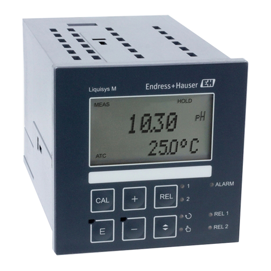
Indicates the working status of relay 1 and 2 LED green: measured value within the permitted limit, relay inactive LED red: measured value outside the permitted limit, relay active Alarm display, e.g. for continuous limit value overshoot. Temperature sensor failure or system error (see error list) Endress+Hauser... -
Page 29: Operating Elements
Field for user labelling 4 main operating keys for calibration and device configuration Changeover switch for automatic/manual mode LEDs for limit contactor relay (switch status) LED for alarm function Display of the active contact and key for relay changeover in manual mode Endress+Hauser... -
Page 30: Key Assignment
(for limit contactor) or set points (for PID controller) assigned to the REL 2 relay in question. Press the PLUS key to jump to the settings of the next relay. Use the REL key to get back to the display mode (automatic return after 30 s). Endress+Hauser... - Page 31 All the settings can continue to be read. The code prompt displays the code 9999. Unlocking the keyboard Press the CAL and MINUS key for at least 3 s to unlock the keyboard. The code prompt displays the code 0. Endress+Hauser...
-
Page 32: Local Operation
• The manual mode has priority over all other automatic functions (Hold). • Hardware locking is not possible in the manual mode. • The manual settings are kept until they are actively reset. • Error code E102 is signalled in the manual mode. Endress+Hauser... -
Page 33: Operating Concept
• Key CAL or ENTER + any code: access to read mode, i.e. all the settings can be read but not modified. The device continues measuring in the read mode. It does not shift to the Hold status. The current output and the controllers remain active. Endress+Hauser... - Page 34 • Any alarm delay is reset to "0". • This function can also be activated externally via the Hold input (see Wiring diagram; binary input 1). • The manual Hold (field S3) remains active even after a power failure. Endress+Hauser...
-
Page 35: System Configuration
Field only available for version "IS" Pt 100 For ISFET sensors: Pt 1K (Pt 1000) Pt100 Select temperature Pt 1K For glass electrodes: Pt 100 sensor NTC 30 K NTC 30k not used Temp None No temperature sensor: Select MTC in B1 Endress+Hauser... - Page 36 1 ... 60 stabilise the display if the measurement is Damping unstable. There is no damping if “1” is entered. No edit option. Glass Note! Sensor Glass Glass electrodes may only be used with zero Sensor point pH 7. Endress+Hauser...
-
Page 37: Setup 2 (Temperature)
-50,0 ... 150,0 °C entered can only be in C. RealTemp °C Temperature Only for B1 = ATC. 0,0 °C difference (offset) is The difference between the measured and -5,0 ... 5,0 °C displayed entered temperature is displayed. Temp.Offs Endress+Hauser... -
Page 38: Current Input
Alarm signalling and dosing switch-off by the main stream Flow in main stream Flow restoration Relay contacts of PID controller Delay for controller switch-off, see field Z2 Alarm relay Delay for controller switch-up, see field Z3 Flow below switch-off limit Z 4 or flow failure Flow alarm Endress+Hauser... - Page 39 Sample arrangement for feedforward control of the flow in the main stream to the PID controller Measuring water extraction point Alkali Static mixer Acid Injection points Liquisys M CPM253 Flowmeter CPA250 with CPS11 Feedforward control is a multiplying function as illustrated in the figure below (example with factory setting): C07-CPM2x3xx-05-06-00-de-003.eps Fig.
- Page 40 When the value is set, the controller actuating Enter value for variable is the same size when feedforward feedforward control at 0 ... 100% control is switched on as when feedforward which gain = 1 applies Kinflu=1 control is switched off. Endress+Hauser...
-
Page 41: Current Outputs
0,166 1,000 First enter the desired current output configuration into the following blank table with a pencil. Calculate the resulting signal distance per mA to observe the necessary minimum slope. Then enter the values in the device. Endress+Hauser... - Page 42 In the case of actuating variable output characteristic Tab = table (3) (O2 = Contr), an increasing current Sel.Type corresponds to an increasing actuating variable. 4-20 4 ... 20 mA O311 Select current range O311 0 ... 20 mA Sel.Range Endress+Hauser...
- Page 43 1 ... No. elem. Assign Sel.Elem. pH 0.00 pH -2.00 ... 16.00 0.00 0 mV O334 O334 Enter x value x value = measured value specified by user. -1500 ... 1500 mV Meas.val. 0.0 % 0.0 ... 100.0 % Endress+Hauser...
- Page 44 Back to O3. Message as to whether If status = no, correct table (all settings made O336 O336 table status is OK up until now are retained) or back to Status ok measuring mode (table is deleted). Endress+Hauser...
-
Page 45: Monitoring Functions
If “no” is selected, all the other alarm settings Set alarm contact to be are deactivated (e.g. alarm delay). The settings effective for the themselves are retained. selected error This setting only applies to the error selected Rel.Assg in F5. Endress+Hauser... - Page 46 • Monitoring of impedance of the reference electrode (alarm if set threshold value overshot). This function can only be selected for symmetrically high-resistance measurement. • Monitoring of leak current for ISFET sensors (pre-alert E168 at I > 200 nA, error E008 at LEAK > 400 nA). LEAK Endress+Hauser...
- Page 47 For this reason, avoid direct sunlight when calibrating and operating. Normal ambient light does not have any effect on the measurement. Alarm threshold monitoring You can use this function to monitor the measured value for permissible upper and lower limits and trigger an alarm. Endress+Hauser...
- Page 48 P7 / P8 result in an alarm. -2.00 Enter lower alarm -2.00 pH Not applicable when P5 = off. threshold -2.00 ... 16.00 pH LowAlarm 16.00 Enter upper alarm 16.00 pH Not applicable when P5 = off. threshold -2.00 ... 16.00 pH HighAlarm Endress+Hauser...
- Page 49 This results in incorrect measurement. With the SCS operating voltage, the supply voltage of a pH sensors with Memosens functionality is monitored. If this value drops below the safety limit, the measured value is ignored and the error E 127 is output. Endress+Hauser...
-
Page 50: Relay Contact Configuration
C07-CxM2x3xx-05-06-00-xx-003.eps Fig. 38: Illustration of the alarm and limit value functions Switch-on point > switch-off point: Max. function Alarm threshold Switch-on point < switch-off point: Min. function Switch-on point Switch-off point Contact ON Alarm ON Alarm OFF Contact OFF Endress+Hauser... - Page 51 • Reduce K slightly and then reduce the integral action time T so that the shortest possible correction time without overshooting is achieved. • To reduce the response time of the controller, also set the derivative action time T Endress+Hauser...
- Page 52 C07-CLM2x3xx-05-06-00-xx-005.eps Fig. 41: Signal of a pulse-length modulated controller contact (left) and of a pulse-frequency modulated controller contact (right) Contact 1 = on, 0 = off Period length Time [s] t Impulse period length (impulse freq. 1/T and 1/T Endress+Hauser...
- Page 53 Connection between cleaning time, pause time and Hold dwell period Wiper and/or spray cleaning system Cleaning time (0 ... 999 s) Hold function Pause time between two cleaning intervals Inactive (1 ... 7200 min) Active Clean Hold dwell period (0 ... 999 s) Endress+Hauser...
- Page 54 • If the cleaning is prematurely aborted, a post rinse time always follows. • If the setting is "Economy", cleaning only takes place with water. C07-CxM2x3xx-05-06-00-xx-008.eps Fig. 44: Sequence of a cleaning cycle Hold Cleaning start Water Pre-rinse time Cleaner Cleaning time Post rinse time Hold dwell period Endress+Hauser...
- Page 55 Sel.Type Clean = Chemoclean (5) and its settings are reset to the factory Neutra controller (6) settings. Switch function of R2 R211 R211 All the settings are retained. (1) off or on Function Endress+Hauser...
- Page 56 Switch function of R2 R221 R221 (2) off or on Function 150.0 °C Enter switch-on 150.0 °C Never set the switch-on point and the R222 R222 temperature -50.0 ... 150.0 °C switch-off point to the same value! On value Endress+Hauser...
- Page 57 Enter set point -1500 ... 1500 mV this value is restored upwards or downwards Setpoint 0.0 % when a deviation occurs. 0.0 ... 100.0 % 1.00 1.00 R233 R233 Enter control gain K See "P(ID) controller" section. 0.01 ... 20.00 Endress+Hauser...
- Page 58 Inlne = continuous process There is no further dosing in the setting range Batch Batch R2312 R2312 Enter process type in batch mode. The I-component is Inlne decreased. Proc.Type Dosing continues in the setting range in inline mode. The I-component is effective. Endress+Hauser...
- Page 59 I+ext = internal + external External suppression is required for irregular CleanTrig I+stp = internal, suppressed by time intervals (e.g. weekends). external 20 s R253 R253 Enter pre-rinse time Rinsing with water takes place. 0 ... 999 s PreRinse Endress+Hauser...
- Page 60 (6) off or on Function Relay assignment 1 and 2 for neutra 6.00 pH 6.00 controller: R262 R262 Enter set point 1 (or 2) pH -2.00 ... 16.00 Rel1 = set point 1 Setpoint1 Rel2 = set point 2 Endress+Hauser...
- Page 61 Inlne = continuous process There is no further dosing in the setting range Batch Batch R2610 R2610 Enter process type in batch mode. The I-component is Inlne decreased. Proc.Type Dosing continues in the setting range in inline mode. The I-component is effective. Endress+Hauser...
-
Page 62: Service
MINUS key and confirmed with the ENTER Chemoclean CleanCode key. "1" is displayed if the code is active. order Order number is If the device is upgraded, the order code is displayed automatically adjusted. PR0005 SerNo Serial number is displayed 12345678 Endress+Hauser... -
Page 63: E+H Service
E141 If E1 = sens: sensor software SW-Vers. E151 E112 E122 xx.xx Hardware version is E112 E132 Only display function displayed E142 HW-Vers. E152 E113 E123 SerNo Serial number is E133 E113 Only display function displayed E143 12345678 E153 Endress+Hauser... -
Page 64: Interfaces
Address and the device is set to multi-drop operation. Display of measuring point @@@@@@@@ Communication For devices with a communication interface, please also refer to the separate Operating Instructions ® ® BA 208C/07/en (HART ) or BA 209C/07/en (PROFIBUS Endress+Hauser... -
Page 65: Calibration
Like all semi-conductor elements, the ISFET chip is sensitive to light (measured value fluctuations). However, this only affects the measured value if the sensor is directly exposed to sunlight. For this reason, avoid direct sunlight when calibrating. Normal ambient light does not have any effect on the measurement. Endress+Hauser... - Page 66 Glass: pH 7.00 pH 5.00 ... 9.00 Zero point (zero 7.00 Antimony: pH 1.00 point / U_is) is For ISFET, the zero point is displayed in mV. pH -1.00 ... 3.00 displayed Zero ISFET: current value -500 ... +500 mV Endress+Hauser...
- Page 67 If C24 = E xxx, then only No or New. Store calibration If New, return to C. result? If Yes/No, return to "Measurement". Store CALIBRATION function group: Sensor adjustment with compensation for C (3) Calibration redox % Calibration for redox wall effects. CALIBRAT Endress+Hauser...
- Page 68 Calibration status is o.k. displayed E xxx Status If C35 = E xxx, then only No or New. Store calibration If New, return to C. result? If Yes/No, return to "Measurement". Store The electrode can now be reinstalled in the process. Endress+Hauser...
- Page 69 For A4 = ISFET: enter the voltage U from Enter zero point -1.00 ... 3.00 pH the quality certificate. Zero ISFET: 0 mV -500 ... +500 mV o.k. Calibration status is o.k. displayed E xxx Status Store calibration result? Store Endress+Hauser...
- Page 70 0.0 % -50.0 ... 50.0 % o.k. Calibration status is o.k. displayed E xxx Status If V3 = E xxx, then only No or New. Store calibration If New, return to V. result? If Yes/No, return to "Measurement". Store Endress+Hauser...
-
Page 71: Commissioning
Normal ambient light does not have any effect on the measurement. Function check Warning! • Check all connections for correctness. • Make sure that the supply voltage is identical to the voltage written on the nameplate! Endress+Hauser... -
Page 72: Switching On
• E+H SERVICE (E) • INTERFACE (I) Calibration and offset mode • CALIBRATION (C) • NUMERIC (N) • OFFSET (V) Note! A detailed explanation of the function groups available in the transmitter can be found in the "System configuration" section. Endress+Hauser... - Page 73 • Device in operation • Error message present (alarm LED red) • No error message present (Alarm LED off) • Device defective or voltage-free (alarm LED off) › Relay energised › Relay de-energised › Contact 42/43 closed › Contact 41/42 closed Endress+Hauser...
-
Page 74: Quick Start-Up
13. In A5, select the temperature sensor the electrode Pt 100 used has, e.g. "Pt 100" for a glass electrode. Pt100 Pt 1K Press to confirm your entries. NTC 30K The display returns to the initial display of the "Setup Temp None 1" function group. Endress+Hauser... - Page 75 19. The difference between the measured and entered °C temperature is displayed. 0.0 °C Press -5.0 ... 5.0 °C The display returns to the initial display of the Temp.Offs "Setup 2" function group. 20. Press simultaneously to switch to the measurement mode. Endress+Hauser...
-
Page 76: Maintenance
– Disconnect the connected strand (pH input, strand comes from the BNC connection jack). – Using a fine side-cutting pliers, nip off the heads of the synthetic distance holders. – Then remove the module from above. Assembly is the reverse of the disassembly sequence. Tighten the special screw hand-tight without a tool. Endress+Hauser... -
Page 77: Dismantling Of Field Instrument
Use the part number on the central module to check whether the new module has the same part number as the previous module. Assemble the device with the new module. Start up the device again and check the basic functions (e.g. measured value and temperature display, operation via keyboard). Endress+Hauser... -
Page 78: Maintenance Of The Entire Measuring Point
• Diluted acids (max. 3%) • Diluted alkalis (max. 5%) • Esters • Hydrocarbons • Ketones • Household cleaners " Caution! For cleaning purposes, never use: • Concentrated mineral acids or alkalis • Benzyl alcohol • Methylene chloride • High-pressure steam Endress+Hauser... -
Page 79: Cleaning The Ph/Redox Sensors
– Clean the sensor. For this purpose, use the cleaning agent indicated for the sensor. – Inspect the sensor for cracks or other damage. – Regenerate the sensor if it is not damaged. Store it for 24 hours in a 3M KCl solution. – Recalibrate the sensor for the next use. Endress+Hauser... -
Page 80: Liquid Kcl Supply
• Upload/download a hex dump to duplicate configurations. The Optoscope serves as an interface between the transmitter and PC / laptop. The information exchange takes place via the optical interface on the transmitter and via an RS 232 interface on the PC / laptop (see "Accessories"). Endress+Hauser... -
Page 81: Accessories
For pH/redox electrodes with GSA plug-in head, with three electrode connectors Order as per product structure, see Technical Information (TI118C/07/en) • Special measuring cable CPK12 For pH glass electrodes and ISFET sensors with TOP68 plug-in head Order as per product structure, see Technical Information (TI 118C/07/en) Endress+Hauser... -
Page 82: Mounting Accessories
Mounting accessories • Weather protection cover CYY101 for mounting of field housing, for outdoor installation material: stainless steel 1.4031; order no. CYY101-A 270 / 10.63 300 / 11.81 mm / inch C07-CYY101xx-00-06-00-en-001.eps Fig. 49: Weather protection cover for field instrument Endress+Hauser... - Page 83 • Kit for mounting of field housing on horizontal or vertical pipes (Ø max. 60 mm (2.36")) order no. 50086842 90 / 3.54 Ø max. 60 / 2.36 70 / 2.76 Ø 6 / 0.24 70 / 2.76 90 / 3.54 mm / inch C07-CxM2x3xx-00-06-00-en-001.eps Fig. 51: Pipe mounting kit Endress+Hauser...
-
Page 84: Assemblies
• Plus Package Order no. 51500385 • Chemoclean Order no. 51500963 • Two-relay card Order no. 51500320 • Four-relay card Order no. 51500321 • Two-relay card with current input Order no. 51504304 • Four-relay card with current input Order no. 51504305 Endress+Hauser... -
Page 85: Calibration Solutions
Interface between transmitter and PC / laptop for service purposes. The Windows software "Scopeware" required for the PC or laptop is supplied with the Optoscope. The Optoscope is supplied in a sturdy plastic case with all the accessories required. Order no. 51500650 Endress+Hauser... -
Page 86: Trouble-Shooting
— — software. software not suitable to hardware 4. If the error persists, send in the device for repair (controller) to your local Endress+Hauser subsidiary or replace the device. Invalid configuration. Repeat download, check E003 Download error optoscope. Instrument software version not... - Page 87 Check that the sensor is correctly connected, the E147 Sensor communication faulty cable ends are correctly wired at the terminals and the cable is not damaged. E152 PCS alarm Check sensor and connection. Endress+Hauser...
- Page 88 Check electrode for contamination and damage; E177 SCS reference electrode warning clean electrode; measuring can continue until the error occurs. If this error occurs, there is no possibility of starting a cleaning session (field F8 not applicable with this error). Endress+Hauser...
-
Page 89: Process Specific Errors
Impermissible device operating status Switch device off and then on again. grounding, screens and line routing or have (no reaction to key actuation) checked by Endress+Hauser Service. Wiring diagram "Electrical connection" Incorrect sensor connection Check connections using wiring diagram. section... - Page 90 E+H when a Plus Package is ordered) serial number (see nameplate) by hand, then enter existing code number. No HART or PROFIBUS No communication possible for several Several devices at the same address Check addresses and re-enter if necessary. communication devices of the same address. Endress+Hauser...
- Page 91 Line problems (too long, cross-section too small, not screened, screen not grounded, cores not twisted) Bus voltage too low The voltage at the device PA/DP (Bus voltage typ. 24 V DC for non-Ex) connection must be at least 9 V. Endress+Hauser...
-
Page 92: Instrument Specific Errors
Compare line voltage and nameplate data. User, electrical technician Device gets hot Power unit defective Replace power unit. Diagnosis only by Endress+Hauser Service Measuring input test: Transmitter module defective (module: If test negative: replace module (note Measured value pH/mV – Connect pH, ref and PM directly at the MKIC), please first carry out tests and variant). - Page 93 Tests and/or remedial measures Execution, tools, spare parts If retrofitting: check whether the correct No or incorrect release code used serial number was quoted when ordering Handled by Endress+Hauser Sales the S-package. Additional functions (S-package) missing Check whether serial number on the...
-
Page 94: Spare Parts
• Serial number (serial no.) • Software version where available Refer to the nameplate for the order code and serial number. The software version is displayed in the instrument sofware (see chapter "Instrument configuration") if the instrument processor system is functional. Endress+Hauser... -
Page 95: Panel Mounted Instrument
Fig. 52: Exploded drawing of panel-mounted instrument The exploded drawing contains the components and spare parts of the panel-mounted instrument. You can take the spare parts and the corresponding order number from the following section using the item numbers. Endress+Hauser... - Page 96 Terminal strip Terminal strip for relay module 51501078 BNC connector, elbowed pH/mV connection 50074961 Fuse Part of power unit, item 10 Choice of line voltage Position of jumper item 30 on power unit, item 10 depending on line voltage Endress+Hauser...
-
Page 97: Field Instrument
460a 10/20 290/300 450c C07-CxM253xx-09-06-06-xx-001.eps Fig. 53: Field device exploded drawing The exploded drawing contains the components and spare parts of the field device. You can take the spare parts and the corresponding order number from the following section. Endress+Hauser... - Page 98 LSR1-x (bottom) and power unit LSGA/LSGD (top) Fuse also accessible if electronics box installed Fuse Part of power unit, item 10 Choice of line voltage Position of jumper item 30 on power unit, item 10 depending on desired line voltage Endress+Hauser...
-
Page 99: Return
Operating Instructions) with the packaging and the transportation documents. No repair without completed "Declaration of contamination"! Disposal The device contains electronic components and must therefore be disposed of in accordance with regulations on the disposal of electronic waste. Please observe local regulations. Endress+Hauser... -
Page 100: Technical Data
Switching capacity with ohmic Max. 1250 VA AC, 150 W DC load (cos ϕ = 1): Switching capacity with inductive Max. 500 VA AC, 90 W DC load (cos ϕ = 0.4): Limit contactor Pick-up/drop-out delay 0 ... 2000 s Endress+Hauser... -
Page 101: Power Supply
38.00 ... 65.00 mV/pH (nominal 59.16 mV/pH) Antimony electrode: 25.00 ... 65.00 mV/pH (nominal 59.16 mV/pH) ISFET sensor 38.00 ... 65.00 mV/pH (nominal 59.16 mV/pH) Offset ±2 pH units Redox: ±120 mV/±50 % Temperature: ±5 °C In accordance with IEC 746-1, for nominal operating conditions Endress+Hauser... -
Page 102: Environment
Order no. 51501839 communication with Liquisys M CxM 223/253, BA 209C/07/en; HART, field communication with Order no. 51501609 Liquisys M CxM 223/253, BA 208C/07/en; Liquisys M CXM223/253/223F/253F Order no. 51515755 safety instructions for electrical equipment in Ex-areas; Zone 2 XA 194C/07/a3 Endress+Hauser... - Page 103 Liquisys M CPM223/253 Technical data Endress+Hauser...
-
Page 104: Appendix
Select error number Set alarm contact to be effective ALARM Latch = latching contact; ; min 0 s (min) 22 mA Momen = momentary cont. 0 s... 2000 s (min) 2,4 mA 1... 255 ; no (depends on F2) C07-CPM2x3xx-13-06-00-en-001.eps Endress+Hauser... - Page 105 Automatic start of Activate error current for Select "next error" cleaning function or return to menu previously set error ; yes (not always displayed next = next error; ; yes Field for customer see error messages) ¬R settings C07-CPM2x3xx-13-06-00-en-002.eps Endress+Hauser...
- Page 106 Module name Contr = controller is displayed is displayed F unction group SW version E + H SERVICE HW version E1(1) E111 E112 E113 E114 Function group Enter address Tag is displayed INTERFACE HART: ...15 or PROFIBUS 1... @@@@@@@@ C07-CPM2x3xx-13-06-00-en-003.eps Endress+Hauser...
- Page 107 ; 0...100.0 % R215 R216 R217 Order number Serial number is Perform instrument test Reference voltage Select AC frequency Reset instrument to is displayed displayed is displayed default values ; display Sens = sensor data; Facty = factory settings. C07-CPM2x3xx-13-06-00-en-004.eps Endress+Hauser...
- Page 108 Appendix Liquisys M CPM223/253 Endress+Hauser...
-
Page 109: Index
Field device connection ......18, 24 Freezing of outputs ......34 Endress+Hauser... - Page 110 Wiring........16 Endress+Hauser...
- Page 111 Liquisys M CPM223/253 Endress+Hauser...
- Page 112 www.endress.com/worldwide BA194C/07/en/12.05 51500268 51500268 Printed in Germany / FM+SGML 6.0 / DT...
Need help?
Do you have a question about the Liquisys M CPM253 and is the answer not in the manual?
Questions and answers