
Subscribe to Our Youtube Channel
Related Manuals for Endress+Hauser Liquisys M CLM223


Summary of Contents for Endress+Hauser Liquisys M CLM223
- Page 1 Operating Instructions Liquisys M CLM223/253 Transmitter for Conductivity BA193C/07/en/09.05 51500270 valid as of: Liquisys Software-version 2.32...
- Page 2 Here you can find an overview of the spare parts which can be delivered as well as an overview of the system. ▼ Technical data Page 10 ff. Dimensions Page 95 ff. Ambient and process conditions, weight, materials etc. ▼ Appendix Page 100 ff. Here you can find the operating matrix Endress+Hauser...
-
Page 3: Table Of Contents
Liquisys M CLM223/253 Table of contents Safety instructions ....5 Commissioning ....29 Designated use . - Page 4 Liquisys M CLM223/253 Technical data ....95 10.1 Input ........95 10.2 Output .
-
Page 5: Safety Instructions
Liquisys M CLM223/253 Safety instructions Safety instructions Designated use Liquisys M is a transmitter for determining the conductivity and the resistivity of a liquid medium. The transmitter is particularly suited for use in the following areas: • Ultrapure water • Water treatment •... -
Page 6: Return
Safety instructions Liquisys M CLM223/253 Return If the device requires repair, please send it cleaned to the sales centre responsible. Please use the original packaging, if possible. Notes on safety icons and symbols Safety icons Warning! This symbol alerts you to hazards. They can cause serious damage to the instrument or to persons if ignored. -
Page 7: Identification
Liquisys M CLM223/253 Identification Identification Device designation 2.1.1 Nameplate Compare the order code on the nameplate (on the transmitter) with the product structure (s.b.) and your order. The device version can be identified from the order code. Note! The enabling codes for retrofitting the software for Chemoclean (to the left of the forward slash) or the Plus Package (to the right of the forward slash) are listed under "Codes". -
Page 8: Additional Functions Of The Plus Package
Identification Liquisys M CLM223/253 2.1.3 Additional functions of the Plus Package • Current output table to cover large areas with varying resolution, fields O33x • Process Check System (PCS): live check of the sensor, function group P • Ultrapure water monitoring for "Water for injection" (WFI) and "Purified water" (PW) acc. to... -
Page 9: Installation
3.1.1 Measuring system A complete measuring systems comprises: • The transmitter Liquisys M CLM223 or CLM253 • A sensor with or without an integrated temperature sensor • A measuring cable CYK71 (conductive), CPK9 for Condumax H CLS16 or CLK5 (inductive) -
Page 10: Incoming Acceptance, Transport, Storage
Installation Liquisys M CLM223/253 Incoming acceptance, transport, storage • Make sure the packaging is undamaged! Inform the supplier about damage to the packaging. Keep the damaged packaging until the matter has been settled. • Make sure the contents are undamaged! Inform the supplier about damage to the delivery contents. -
Page 11: Panel-Mounted Instrument
Liquisys M CLM223/253 Installation Removable electronics box Partition plate Terminals Fuse C07-CxM253xx-11-06-00-xx-001.eps Fig. 5: View into the field housing 3.3.2 Panel-mounted instrument 0.24 92 / 3.62 90 / 3.54 mm / inch C07-CxM223xx-06-06-00-en-001.EPS Fig. 6: Panel-mounted instrument Endress+Hauser... -
Page 12: Installation Instructions
Installation Liquisys M CLM223/253 Installation instructions 3.4.1 Field instrument There are several ways of securing the field housing: • Wall mounting with fixing screws • Post mounting to cylindrical pipes • Post mounting to square securing mast Note! When mounting in the open air with unprotected exposure to weather conditions, a weather protection cover (see Accessories) is required. - Page 13 Liquisys M CLM223/253 Installation Transmitter post mounting Note! You require a post mounting kit to secure the field device to horizontal and vertical posts or pipes (max. Ø 60 mm(2.36")). This can be acquired as an accessory (see "Accessories" section).
- Page 14 Installation Liquisys M CLM223/253 You can also secure the field device to a square universal post in conjunction with the weather protection cover. These can be acquired as accessories, see "Accessories" section. C07-CxM253xx-11-06-00-xx-004.eps Fig. 9: Mounting field device with universal posts and weather protection cover For mounting the weather protection cover, proceed as follows: Screw the weather protection cover with 2 screws (bores 1) to the upright post (bores 2).
-
Page 15: Panel-Mounted Instrument
Liquisys M CLM223/253 Installation 3.4.2 Panel-mounted instrument The panel-mounted instrument is secured with the clamping screws supplied (see → Fig. 10). The necessary installation depth is approx. 165 mm (6.50"). +0.5 +0.02 / 3.62 max. 45 / 1.77 approx. 25 / 139 / 5.47... -
Page 16: Wiring
Wiring Liquisys M CLM223/253 Wiring Warning! • The electrical connection must only be carried out by authorised technical personnel. • Technical personnel must have read and understood the instructions in this manual and must adhere to them. • Ensure that there is no voltage at the power cable before beginning the connection work. -
Page 17: Electrical Connection
Liquisys M CLM223/253 Wiring Electrical connection 4.1.1 Connection diagram The wiring diagram depicted in Fig. 11 shows the connections of an instrument equipped with all the options. Connecting the sensors and the various measuring cables is explained in more detail in the "Measuring cables and sensor connection"... - Page 18 Wiring Liquisys M CLM223/253 Note! • The device is approved for protection class II and is generally operated without a protective earth connection. • To guarantee measuring stability and functional safety, you have to ground the outer screen of the sensor cable: –...
-
Page 19: Measuring Cable And Sensor Connection
Liquisys M CLM223/253 Wiring " Caution! • Terminals marked NC may not be wired. • Unmarked terminals may not be wired. Note! Please label the sensor terminal block with the sticker provided. 4.1.2 Measuring cable and sensor connection You require screened special measuring cables to connect conductivity sensors to the transmitter. - Page 20 Wiring Liquisys M CLM223/253 Field instrument measuring cable connection Proceed as follows to connect a conductivity sensor to the field instrument: Open the housing cover to access the terminal block in the connection compartment. Break the punching of a cable gland from the housing, mount a cable gland and guide the cable through this cable gland.
-
Page 21: Alarm Contact
Liquisys M CLM223/253 Wiring 4.1.3 Alarm contact C07-CxM2x3xx-04-06-00-xx-001.eps Fig. 17: Recommended fail-safe switching for the alarm contact A Normal operating status B Alarm condition Normal operating status: Alarm condition • Device in operation • Error message present (alarm LED red) •... -
Page 22: Operation
Operation Liquisys M CLM223/253 Operation Quick operation guide You have the following ways of operating the transmitter: • On site via the key field ® • Via the HART interface (optional, with corresponding order version) per: ® – HART handheld terminal or ®... -
Page 23: Operating Elements
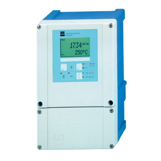
Liquisys M CLM223/253 Operation LC display mS/cm R232 Setpoint C07-CLM2x3xx-07-06-00-en-004.eps Fig. 18: LC display transmitter Indicator for measuring mode (normal operation) In measuring mode: measured variable Indicator for calibration mode In setup mode: configured variable Indicator for setup mode (configuration) In measuring mode: secondary measured value Indicator for "Hold"... -
Page 24: Key Assignment
Operation Liquisys M CLM223/253 5.2.3 Key assignment CAL key When you press the CAL key, the device first prompts you for the calibration access code: • Code 22 for calibration • Code 0 or any other code for reading the last calibration data Use the CAL key to accept the calibration data or to switch from field to field within the calibration menu. -
Page 25: Endress+Hauser
Liquisys M CLM223/253 Operation AUTO key You can use the AUTO key to switch between automatic mode and manual mode. Escape function If you press the PLUS and MINUS key simultaneously, you return to the main menu or are taken to the end of calibration if calibrating. If you press the PLUS and MINUS key again, you return to the measuring mode. -
Page 26: Local Operation
Operation Liquisys M CLM223/253 Local Operation 5.3.1 Automatic/manual mode The transmitter normally operates in automatic mode. Here, the relays are triggered by the transmitter. In the manual mode, you can trigger the relays using the REL key or start the cleaning function. -
Page 27: Operating Concept
Liquisys M CLM223/253 Operation 5.3.2 Operating concept Operating modes Measuring mode: standard mode of operation, displaying current measured values Calibration mode: Setup mode access to all execution of configuration calibration routine settings Code The function groups are selected with the PLUS or MINUS key. -
Page 28: Endress+Hauser
Operation Liquisys M CLM223/253 Menu structure The configuration and calibration functions are arranged in function groups. • In the setup mode, select a function group with the PLUS and MINUS keys. • In the function group itself, switch from function to function with the ENTER key. -
Page 29: Commissioning
Liquisys M CLM223/253 Commissioning Commissioning Function check Warning! • Check all connections for correctness. • Make sure that the supply voltage is identical to the voltage written on the nameplate! Switching on Familiarise yourself with the operation of the transmitter before it is first switched on. Please refer in particular to the "Safety instructions"... - Page 30 Commissioning Liquisys M CLM223/253 Selecting and locating functions is facilitated by a code displayed for each function in a special display field Fig. 22. C131 C132 C133 The structure of this coding is given in Fig. 23. The first column indicates the function group as C121 a letter (see group designations).
-
Page 31: Quick Start-Up
Liquisys M CLM223/253 Commissioning Quick start-up After power-up, you must make some settings to configure the most important functions of the transmitter which are required for correct measurement. The following section gives an example of this. User input Setting range... - Page 32 Commissioning Liquisys M CLM223/253 User input Setting range Display (Factory settings, bold) 0 Ω 14. In A6, enter the resistance of the cable (conductive 0 ... 99.99 Ω sensors only). Cable-Res 15. If you need to stabilise the display, enter the required damping factor in A7.
- Page 33 Liquisys M CLM223/253 Commissioning User input Setting range Display (Factory settings, bold) Out1 25. In O1, select your output, e.g. "Out1" = output 1. Out1 Press to confirm. Out2 Sel.Out lin = linear (1) 26. In O3, select the linear characteristic.
-
Page 34: System Configuration
Commissioning Liquisys M CLM223/253 System configuration 6.4.1 Setup 1 (Conductivity) In the SETUP 1 function group, you can change the operating mode and the sensor settings. Basic version does not include functions in italic. Coding Field Selection or range Display... -
Page 35: Setup 2 (Temperature)
Liquisys M CLM223/253 Commissioning 6.4.2 Setup 2 (Temperature) The temperature coefficient α specifies the change in conductivity per degree of temperature change: k(T) k(T ) (T - T )) with κ (T) = conductivity at process temperature T κ (T... - Page 36 Commissioning Liquisys M CLM223/253 Ultrapure water compensation (for conductive sensors) For pure and ultrapure water, algorithms are saved in the transmitter that account for the self-dissociation of ultra pure water and its strong temperature dependency. They are used for conductivities of approx. 100 µS/cm verwendet.
- Page 37 Liquisys M CLM223/253 Commissioning In the SETUP 2 function group, you can change the settings for temperature measurement. Basic version does not include functions in italic. Coding Field Selection or range Display Info (factory settings bold) Function group Settings for temperature measurement.
-
Page 38: Current Input
Commissioning Liquisys M CLM223/253 6.4.3 Current input To use the "Current input" function group, you need a relay board with current input which is not part of the basic version. With this function group you can monitor process parameters and use these for feedforward control. - Page 39 Liquisys M CLM223/253 Commissioning Feedforward control to PID controller For control systems with very short reaction times, you can optimise the control. Additionally you measure the flow rate of the medium. This flow rate value (0/4 ... 20 mA) you apply as feedforward control to the PID controller.
- Page 40 Commissioning Liquisys M CLM223/253 Basic version does not include functions in italic. Coding Field Setting range Display Info (Factory settings, bold) CURRENT INPUT Current input settings. function group CUR.INPUT Select flow Flow monitoring may only be switched on if monitoring of main...
-
Page 41: Current Outputs
Liquisys M CLM223/253 Commissioning 6.4.4 Current outputs Use the "Current output" function group to configure the individual outputs. You can enter either a linear characteristic (O3 (1)) or a user-defined current output characteristic in conjunction with the Plus Package (O3 (3)). Exception: if you have chosen a "continuous controller" for current output 2, you cannot enter a user-defined current output characteristic for this current output. - Page 42 Commissioning Liquisys M CLM223/253 Current output 1 Current output 2 Value pair [mS/cm] Current Distance [mS/cm] Current Distance [%] [°C] [mA] per mA [%] [°C] [mA] per mA Basic version does not include functions in italic. Coding Field Setting range...
- Page 43 Liquisys M CLM223/253 Commissioning Coding Field Setting range Display Info (Factory settings, bold) cond/ind: 0.00 µS/cm Here you can enter the measured value at µS/cm 0/4 mA value: 0.00 MOhm: 0.00 k Ω⋅ cm which the min. current value (0/4 mA) is...
-
Page 44: Alarm
Commissioning Liquisys M CLM223/253 Coding Field Setting range Display Info (Factory settings, bold) Back to O3. Message as to If status = no, correct table (all settings made O336 O336 whether table status is up until now are retained) or back to Status ok measuring mode (table is deleted). -
Page 45: Check
Liquisys M CLM223/253 Commissioning Coding Field Setting range Display Info (Factory settings, bold) The option selected in F4 is effective or Set error current to be ineffective in the event of an error. effective for the This setting only applies to the error selected selected error Curr.Assg... - Page 46 Commissioning Liquisys M CLM223/253 C07-CxM2x3xx-05-06-00-xx-001.eps Fig. 30: PCS alarm (live check) Constant measuring signal = alarm triggered after PCS alarm time has elapsed Note! Any PCS alarm pending is automatically deleted as soon as the sensor signal changes. Basic version does not include functions in italic.
- Page 47 Liquisys M CLM223/253 Commissioning Coding Field Setting range Display Info (Factory settings, bold) AC = sensor alternation check (E152) CC = controller check (E156, E157) Select process Alarm signalling optionally with or without monitoring AC+CC simultaneous controller switch-off. (PCS alarm)
-
Page 48: Relay Contact Configuration
Commissioning Liquisys M CLM223/253 6.4.7 Relay contact configuration To use the RELAY function group you need a relay board which is not part of the basic version. The following relay contacts can be selected and configured as desired (max. four contacts, depending on options installed): •... - Page 49 Liquisys M CLM223/253 Commissioning P(ID) controller You can define various controller functions for the transmitter. On the basis of the PID controller, P, PI, PD and PID controllers can be implemented. For an optimum control system, use the controller that best suits your application. Depending on the option selected in the R 237 field, the actuating signal can be output via relays or via current output 2 (if available).
- Page 50 Commissioning Liquisys M CLM223/253 Control and fine optimisation of the set parameters with a recorder C07-CxM2x3xx-05-06-00-xx-004.eps Fig. 33: Optimisation of settings T and K Actual value too small too small Time too large Optimum setting too large Actuating signal outputs (R237 ... R2310) Each control contact outputs a cyclical signal whose intensity corresponds to the controller's manipulated variable.
- Page 51 Liquisys M CLM223/253 Commissioning Constant controller Via the current output 2, the minimum actuating variable (0 %) of the controller is output with 0/4 mA and the maximum actuating variable (100%) of the controller is output with 20 mA. Control characteristic for direct and inverse control action You can choose between two control characteristics in the R236 field: •...
- Page 52 Commissioning Liquisys M CLM223/253 Chemoclean function Just like the timer function, Chemoclean can also be used to start a cleaning cycle. However, Chemoclean also gives you the added option of defining different cleaning and rinsing intervals. As a result, it is possible to clean irregularly with different repeat cycles and to separately set the cleaning times with post rinse times.
- Page 53 Liquisys M CLM223/253 Commissioning Limit values for pharaceutical water according to United States Pharmacopeia (USP) and European Pharmacopoeia (EP) (conductive only) The transmitter (conductive sensors only) can monitor "Water for Injection" (WFI), "Highly Purified Water" (HPW) and "Purified Water" (PW) according to the standard United States Pharmacopeia (USP) part 645 and European Pharmacopoeia (EP).
- Page 54 Commissioning Liquisys M CLM223/253 Note! • To use the USP and EP functions the transmitter has to be equipped with a relay board and the Plus Package. • For alarm output, activate the fault-signalling contact or the error current in field F5 - F7 (error code E151 and E153).
- Page 55 Liquisys M CLM223/253 Commissioning Coding Field Setting range Display Info (Factory settings, bold) R215 R215 Enter drop-out delay 0 ... 2000 s Off Delay If the alarm threshold is undershot/overshot, this triggers an alarm with the error message mS/cm cond/ind: 9999 mS/cm...
- Page 56 Commissioning Liquisys M CLM223/253 Coding Field Setting range Display Info (Factory settings, bold) If the alarm threshold is undershot/overshot, this triggers an alarm with the error message ° 250.0 Enter alarm threshold 250.0 C (E067 to E070) and error current at the...
- Page 57 Liquisys M CLM223/253 Commissioning Coding Field Setting range Display Info (Factory settings, bold) Pulse length e.g. for solenoid valve, pulse len = pulse length frequency e.g. for solenoid dosing pump, see Select pulse length or R237 R237 freq = pulse frequency "Actuating signal outputs"...
- Page 58 Commissioning Liquisys M CLM223/253 Coding Field Setting range Display Info (Factory settings, bold) Enter minimum pause 120 min The minimum pause time prevents constant R244 R244 time 1 ... R243 min cleaning if a cleaning trigger is present. Min.Pause LC PV = limit contactor cond...
- Page 59 Liquisys M CLM223/253 Commissioning Coding Field Setting range Display Info (Factory settings, bold) The minimum pause time prevents constant Enter minimum pause 120 min R258 R258 cleaning if an external cleaning start is time 1 ... R257 min present. Min.Pause...
- Page 60 Commissioning Liquisys M CLM223/253 Coding Field Setting range Display Info (Factory settings, bold) The pre-alarm effects a contact query. Should the alarm value be reached (100 %) 80.0 Pre-alarm threshold: 80 % the alarm relay also responds. Example: At R272...
-
Page 61: Temperature Compensation With Table
Liquisys M CLM223/253 Commissioning 6.4.8 Temperature compensation with table You need the Plus Package to use the function group "ALPHA TABLE". This function group is used to perform a temperature compensation with table (field B2). Enter the α− T value pairs in the fields T4 and T5. -
Page 62: Concentration Measurement
Commissioning Liquisys M CLM223/253 6.4.9 Concentration measurement You need the Plus Package to use the function group "CONCENTRATION". The transmitter can convert conductivity values to concentration values. For this, set the operating mode to Concentration measurement (see field A1). Then, you must enter the basic data to which the concentration calculation should refer. - Page 63 Liquisys M CLM223/253 Commissioning Note! κ κ The characteristics received from the measuring points must be strictly monotonously increasing or strictly monotonously decreasing in the range of the process conditions. Therefore, neither maxima / minima nor ranges with a constant behaviour can occur.
- Page 64 Commissioning Liquisys M CLM223/253 Coding Field Selection or range Display Info (factory settings bold) When editing a curve, another curve should be used to calculate the corresponding values. Selection of table to Example: When editing curve 2, either be edited 1 ...
-
Page 65: Service
Liquisys M CLM223/253 Commissioning 6.4.10 Service Coding Field Setting range Display Info (Factory settings, bold) SERVICE function Service function settings. group SERVICE ENG = English GER = German This field has to be configured once during FRA = French Select language device configuration. -
Page 66: E+H Service
Commissioning Liquisys M CLM223/253 Coding Field Setting range Display Info (Factory settings, bold) Reset the device to the Sens = last calibration is deleted and is reset to basic settings factory setting. Sens = sensor data Facty = all data (apart from A1 a. S1) are... -
Page 67: Interfaces
Liquisys M CLM223/253 Commissioning 6.4.12 Interfaces Coding Field Setting range Display Info (Factory settings, bold) INTERFACE Communication settings (only for device function group version HART or PROFIBUS). INTERFACE Each address may only be given once in a Address network. HART: 0 ... 15 If a device address ≠... -
Page 68: Calibration
Commissioning Liquisys M CLM223/253 Calibration To access the "Calibration" function group, press the CAL key. This function group is used to calibrate and adjust the transmitter. Two different types of calibration are possible: • Calibration by measurement in a calibration solution of a known conductivity. - Page 69 Liquisys M CLM223/253 Commissioning Coding Field Selection or range Display Info (factory settings bold) If the calibration status is not o.k., the second o.k. Calibration status is o.k. C113 C113 display line shows an explanation of the displayed E xxx error.
- Page 70 Commissioning Liquisys M CLM223/253 Coding Field Selection or range Display Info (factory settings bold) If C125 = E xxx, then only no or new. Store calibration C126 C126 If new, return to C. results? If yes/no, return to “Measurement”. Store...
-
Page 71: Maintenance
Liquisys M CLM223/253 Maintenance Maintenance Take all the necessary measures in time to guarantee the operational safety and reliability of the entire measuring system. Maintenance work at the transmitter comprises: • Calibration (see "Calibration" section) • Cleaning of assembly and sensor •... -
Page 72: Cleaning The Conductivity Sensors
Maintenance Liquisys M CLM223/253 7.1.2 Cleaning the conductivity sensors Please clean contamination on the sensor as follows: • Oily and greasy films: Clean with detergent (grease dissolvers, such as alcohol, acetone, poss. washing-up liquids). Warning! When using the following cleaning agents, make sure to protect your hands, eyes and clothing! •... - Page 73 Liquisys M CLM223/253 Maintenance Conductivity For conductivity, the values in the following table are valid, if the cell constant k is set to the nominal value according to column 2. ] ⋅ 1 / R[k Ω ] Otherwise: Display conductivity[mS/cm] = k[cm Display for M Ω...
-
Page 74: Simulation Of Inductive Sensors For Device Test
Maintenance Liquisys M CLM223/253 7.1.4 Simulation of inductive sensors for device test The inductive sensor cannot be simulated. However, the overall system comprising the transmitter and inductive sensor can be checked using equivalent resistances. Note the cell constant (k = 1.98 cm for CLS 50, k = 5.9 cm... -
Page 75: Check Of Inductive Sensors
Liquisys M CLM223/253 Maintenance 7.1.6 Check of inductive sensors The following specifications apply to the CLS50 and CLS52 sensors. The sensor lines on the instrument or junction box are to be disconnected for all tests described here! • Testing transmitting and receiving coils –... -
Page 76: Accessories
Accessories Liquisys M CLM223/253 Accessories Sensors • Condumax W CLS12 Conductive conductivity sensor for standard, Ex and high temperature applications; Ordering acc. to version, see Technical Information TI 082/C07/en • Condumax W CLS13 Conductive conductivity sensor for standard, Ex and high temperature applications;... -
Page 77: Mounting Accessories
Liquisys M CLM223/253 Accessories Mounting accessories • Weather protection cover CYY101 for mounting of field housing, for outdoor installation material: stainless steel 1.4031; order no. CYY101-A 270 / 10.63 300 / 11.81 mm / inch C07-CYY101xx-00-06-00-en-001.eps Fig. 41: Weather protection cover for field instrument •... -
Page 78: Assemblies
Accessories Liquisys M CLM223/253 • Kit for mounting of field housing on horizontal or vertical pipes (Ø max. 60 mm (2.36")) order no. 50086842 90 / 3.54 Ø max. 60 / 2.36 70 / 2.76 Ø 6 / 0.24 70 / 2.76 90 / 3.54... -
Page 79: Software And Hardware Add-Ons
Liquisys M CLM223/253 Accessories • Dipfit P CLA140 For the inductive sensor CLS50 Immersion assembly with flange connection for high duty processes; Ordering acc. to the version, see Technical Information (TI196C/07/en)) • CLA751 flow assembly For installation of conductivity sensors with G 1 Ø... -
Page 80: Trouble-Shooting
Trouble-shooting Liquisys M CLM223/253 Trouble-shooting Trouble-shooting instructions The transmitter constantly monitors its functions itself. If an error occurs which the device recognises, this is indicated on the display. The error number is under the unit display of the main measured value. If more than one error occurs, you can call these up with the MINUS key. - Page 81 Liquisys M CLM223/253 Trouble-shooting Error Display Tests and/or remedial measures Alarm contact Error current Autom. cleaning start Facty User Facty User Facty User Main parameter measuring range E057 exceeded Check measurement and connections; check device E059 Below temperature measuring range and measuring cable with simulator if necessary.
- Page 82 Trouble-shooting Liquisys M CLM223/253 Error Display Tests and/or remedial measures Alarm contact Error current Autom. cleaning start Facty User Facty User Facty User Below lower alarm threshold for E154 period exceeding alarm delay Above upper alarm threshold for E155 period exceeding alarm delay...
-
Page 83: Process Specific Errors
Liquisys M CLM223/253 Trouble-shooting Process specific errors Use the following table to locate and correct errors. Error Possible cause Tests and / or remedial measures Equipment, spare parts, personnel Calibration faulty Calibrate instrument according to chapter Calibration solution or sensor certificate "Calibration". - Page 84 Trouble-shooting Liquisys M CLM223/253 Error Possible cause Tests and / or remedial measures Equipment, spare parts, personnel No / incorrect temperature ATC: select compensation type; linear: set compensation correct coefficient. MTC: set process temperature. Incorrect temperature measurement Check temperature value.
- Page 85 Liquisys M CLM223/253 Trouble-shooting Error Possible cause Tests and / or remedial measures Equipment, spare parts, personnel Instrument does not have 2nd current Refer to nameplate for variant; change Module LSCH-x2, No temperature output output LSCH-x1 module if necessary. see chapter "Spare parts".
-
Page 86: Instrument Specific Errors
Compare line voltage and nameplate data. User, electrical technician Device gets hot Power unit defective Replace power unit. Diagnosis only by Endress+Hauser Service Measuring input test: Transmitter module defective (module: If test negative: replace module (note – Connect resistor in place of conductivity Incorrect meas. - Page 87 Liquisys M CLM223/253 Trouble-shooting Error Possible cause Tests and/or remedial measures Execution, tools, spare parts Only 2 additional relays can Relay module LSR1-2 installed with 2 Upgrade to LSR1-4 with 4 relays. User or Endress+Hauser Service be triggered relays If retrofitting: check whether the correct...
-
Page 88: Spare Parts
Trouble-shooting Liquisys M CLM223/253 Spare parts Spare parts are to be ordered from your sales center responsible. Specify the order numbers listed in the chapter "Spare parts kits". To be on the safe side, you should always specify the following data with your spare part orders: •... -
Page 89: Panel Mounted Instrument
Liquisys M CLM223/253 Trouble-shooting 9.5.2 Panel mounted instrument 420a 420b 15/20 40 ... 91 290/300 230V 115V 100V C07-CLM223xx-09-06-00-xx-001.eps Fig. 46: Exploded view of panel mounted instrument The exploded drawing contains the components and spare parts of the panel-mounted instrument. - Page 90 Trouble-shooting Liquisys M CLM223/253 Item Kit description Name Function/contents Order number Power unit (main module) LSGA 100 / 115 / 230 V AC 51500317 Power unit (main module) LSGD 24 V AC + DC 51500318 Central module cond. (controller) LSCH-S1...
-
Page 91: Dismantling Of Field Instrument
Liquisys M CLM223/253 Trouble-shooting 9.5.3 Dismantling of field instrument " Caution! Please note the effects on the process if the device is taken out of service! Note! Please refer to the diagram in Section 9.5 for the item numbers. To dismantle the field instrument you need the following tools: •... -
Page 92: Field Instrument
Trouble-shooting Liquisys M CLM223/253 9.5.4 Field instrument Pos. 10 Netzteil 100 – 230 V AC Sicherung 230 V 115 V 460b 100 V 40 ... 91 450b 450a 310/320 460a 15/20 290/300 450c C07-CLM253xx-09-06-00-xx-001.eps Fig. 47: Exploded drawing of field instrument... - Page 93 Liquisys M CLM223/253 Trouble-shooting The exploded drawing contains the components and spare parts of the field device. You can take the spare parts and the corresponding order number from the following section using the item numbers. Item Kit description Name...
-
Page 94: Replacing The Controller
Trouble-shooting Liquisys M CLM223/253 9.5.5 Replacing the controller Note! Generally, when a central module has been replaced, all data which can be changed are set to the factory setting. Proceed as described below if a central module is replaced: If possible, note the customised settings of the device, such as: –... -
Page 95: Technical Data
Liquisys M CLM223/253 Technical data Technical data 10.1 Input Measured variable Conductivity, resistivity, temperaure Measuring range Conductivity (conductive): 0 ... 60 mS/cm (uncompensated) Conductivity (inductive): 0 ... 2000 mS/cm (uncompensated) 0 ... 200 M Ω⋅ cm Resistivity: Concentration: 0 ... 9999 (%, ppm, mg/l, TDS) Temperature: -35 ... - Page 96 Technical data Liquisys M CLM223/253 Minimum spread 0 / 4 ... 20 mA signal Conductivity: Meas. value 0 ... 1.999 µS/cm 0.2 µS/cm Meas. value 0 ... 19.99 µS/cm 2 µS/cm Meas. value 20 ... 199.9 µS/cm 20 µS/cm Meas. value 200 ... 1999 µS/cm 200 µS/cm...
-
Page 97: Power Supply
Liquisys M CLM223/253 Technical data 10.3 Power supply Supply voltage Depending on ordered version: 100/115/230 V AC +10/-15 %, 48 ... 62 Hz 24 V AC/DC +20/-15 % Power consumption Max. 7.5 VA Mains fuse Fine-wire fuse, semi-delay 250 V/3.15 A 10.4... -
Page 98: Mechanical Construction
Technical data Liquisys M CLM223/253 10.6 Mechanical construction Design/dimensions Panel-mounted instrument: L x W x D: 96 x 96 x 145 mm (3.78" x 3.78" x 5.71") Installation depth: approx. 165 mm (6.50") Field device: L x W x D: 247 x 170 x 115 mm (9.72"... - Page 99 Liquisys M CLM223/253 Technical data Endress+Hauser...
-
Page 100: Appendix
Appendix Liquisys M CLM223/253 Appendix Operating matrix Entry of correct Display of calculated Calibration Calibration temperature Entry of value of Calibration status calibration solution conductivity value of installation factor entry (MTC) is displayed calibration solution InstF 25.0 C ° 2.10 %/K o.k.;... - Page 101 Liquisys M CLM223/253 Appendix Store calibration results yes; no; new C136 Store calibration results yes; no; new C126 Entry of measured value damping (no damping) 1 ... 60 Entry of reference temperature 25 °C –35 ... 250 °C Feedforward control = 1 0 …...
- Page 102 Appendix Liquisys M CLM223/253 Function of R2 (7) Entry of alarm threshold Pickup delay Limit contactor Switch off or on (switch-on point) entry configuration R2 (7) EP PW 80 % 0.0 ... 100.0 % 0 ... 2000 s R274 R271...
- Page 103 Liquisys M CLM223/253 Appendix Dropout delay entry 0 ... 2000 s R275 Dropout delay entry 0 ... 2000 s R265 Number of cleaning Set interval between Set minimum pause Entry of post-rinse time Number of repeat cycles time cycles without...
- Page 104 Appendix Liquisys M CLM223/253 Endress+Hauser...
-
Page 105: Index
Liquisys M CLM223/253 Index Access codes ........27 Icons Accessories . - Page 106 Liquisys M CLM223/253 Relay contact configuration ......48 Replacement of controller ......94 Return.
- Page 107 Liquisys M CLM223/253 Endress+Hauser...
- Page 108 www.endress.com/worldwide BA193C/07/en/09.05 51500270 Printed in Germany / FM+SGML 6.0 / DT 51500270...
Need help?
Do you have a question about the Liquisys M CLM223 and is the answer not in the manual?
Questions and answers