
Subscribe to Our Youtube Channel
Related Manuals for Kobold KAL-8115FL


Summary of Contents for Kobold KAL-8115FL
- Page 1 KOBOLD KAL-L (KAL-8000 Series) Thermal Air Flow Switch User Instructions KOBOLD Instruments Inc. 1801 Parkway View Drive Pittsburgh PA 15205 Phone (412) 788-2830 • Fax (412)-788-4890 Manual-KAL-L_5-12...
-
Page 3: Table Of Contents
KAL-L Table Of Contents General .......................1 Specifications ....................1 Mechanical Installation................3 Installation General ................3 Installation of Units with NPT Thread Connection......5 Installation of Units with HVAC Flange Connection......5 Electrical Connections ................5 Operation ....................6 Flow Setpoint Adjustment ..............6 Adjustment of the Start-up Time Delay ..........8 Maintenance ....................9 Need Help with Your KAL-L Flow Switch? ..........9 List of Diagrams... -
Page 5: General
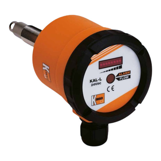
KAL-L CAUTION: For safety reasons, please read the cautionary information located at the end of the manual, before attempting installation. General The KAL-L (KAL-8000 Series) Thermal Air Flow Switch uses the proven calorimetric principle to monitor the flow of air or non-hazardous gases. A sensing resistive thermal device (RTD) is heated to a few degrees above the temperature of the flow medium. -
Page 6: Diagram 2.1: Dimensions
KAL-L Diagram 2.1 Dimensions φ15.5mm Hex 41mm PG 13.5 Cable Gland 1/2” NPT Compression Fitting HVAC Duct Mount Flange All dimensions in inches Unless otherwise noted FM Rev. 5/17/12... -
Page 7: Mechanical Installation
KAL-L Table 2.1 Model Number Codes Model Code Description KAL-8115 15mm smooth bore probe with 1/2” NPT compression fitting KAL-8115FL 15mm diameter probe with clamping flange per DIN 43 743 Options Option Suffix Description -M12 NEMA 4 electrical plug connector 1/2”... -
Page 8: Diagram 3.1: General Installation
KAL-L Diagram 3.1 General Installation Mount the unit in the pipe upper hemisphere 3/8” Min. probe insertion depth. 1/2” or greater is Mount probe such that optimal the notch cut into the hex is perpendicular to the pipe centerline to ensure that the probe is Liquid and sediment properly oriented in the... -
Page 9: Installation Of Units With Npt Thread Connection
KAL-L 3.2.1 Units with NPT threaded connections are best suited for round pipes or ducts in which systems are under pressure. The NPT connection makes a leaktight seal to 120 PSIG. 3.2.2 The threaded connection should be installed into a pipe via a 1/2” weld coupling or a pipe tee with 1/2”... -
Page 10: Operation
KAL-L Operation Diagram 5.1 Interior Controls Layout for the KAL-L Setpoint LED Fixed at 3rd LED Trend Indicator (flashing) 8 LEDs Span Adjustment P1 DUO-LED Green= Flow > Setpoint Relay Activated Red = Flow < Setpoint Relay Deactivated Start-up Time Delay P2 Holds the relay in activated state for 0 to 60 seconds after power-up... - Page 11 KAL-L 5.1.2 Adjustment of Precise Setpoint on Falling Flow To adjust the KAL-L for a precise switchpoint on falling flow, refer to Diagram 5.1 on page 6 and proceed as follows: 5.1.2.1 With power connected to the KAL-L, adjust the span potentiome- ter P1 clockwise to its right hand stop.Turn time delay potentiom- eter P2 counter-clockwise to its far lefthand stop.
-
Page 12: Adjustment Of The Start-Up Time Delay
KAL-L 5.1.4 Setup of the KAL for Flow/No-flow Detection Alternatively, the KAL-L can be quickly set-up to switch on a loss of flow. Using this procedure does not yield a precise switchpoint but is generally acceptable for flow/no- flow detection. When set up in this manner, the KAL-L will switch when approximately a 50% reduction from normal flow occurs. -
Page 13: Maintenance
KAL-L Maintenance The KAL-L is an electronic device which uses no moving parts. This design ensures reliable operation and long service life. Dirt and debris which can build up on the sensing probe over time will result in degraded performance. For this reason we strongly recommend that the proper filtration be installed in the system. - Page 15 KAL-L CAUTION PLEASE READ THE FOLLOWING WARNINGS BEFORE ATTEMPTING INSTALLATION OF YOUR NEW DEVICE. FAILURE TO HEED THE INFORMATION HEREIN MAY RESULT IN EQUIPMENT FAILURE AND POSSIBLE SUBSEQUENT PERSONAL INJURY. FM Rev. 5/17/12...
- Page 16 KAL-L • User's Responsibility for Safety: KOBOLD manufactures a wide range of process sensors and technologies. While each of these technologies are designed to operate in a wide variety of applications, it is the user's responsibility to select a technology that is appropriate for the application, to install it per these installation instructions, to perform tests of the installed system, and to maintain all components.
Need help?
Do you have a question about the KAL-8115FL and is the answer not in the manual?
Questions and answers