
Related Manuals for Kobold PSR


Summary of Contents for Kobold PSR
- Page 1 KOBOLD PSR/PS FLOW SWITCH User Instructions Manual-PSR-PS_ 3-13 1.800.561.8187 information@itm.com www. .com...
-
Page 2: Table Of Contents
Contact Protection ............5 Operation ............... 6 Adjusting Setpoint ............6 Maintenance ..............7 Damaged Equipment ............. 7 Need Help with your PSR/PS ........7 LIST of DIAGRAMS Diagram 2.4 Diagram of Dimensions ..........4 Diagram 2.5 Diagram of Pressure loss vs. Flow rate ......4 Diagram 4.2... -
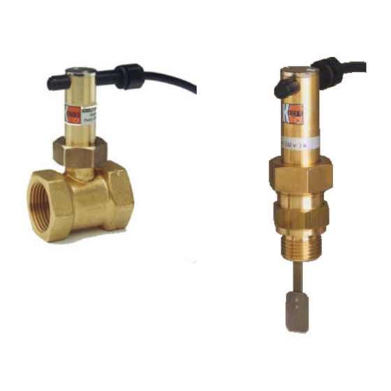
Page 3: Kobold Psr/Ps Flow Switch
( in the T-piece ). The paddle pivots about a point higher in the PSR/PS body but is resisted by a leaf spring. On the upper part of the paddle is a magnet, which moves as the paddle pivots about its center. A reed switch is located outside the PSR/PS housing ( thus hermetically isolated ) inside a movable plastic housing. -
Page 4: Table 2.2 Table Of Construction
PSR/PS Table 2.2: Construction Housing Brass (1,4,6) Impact Plate 304 SS 304 SS (3.1) Leaf Spring 301 SS 301 SS (3.4) Lever (3.2) 301 SS 301 SS Locking Plate Brass Brass Housing (7) Polyamide Polyamide GFR* GFR* Cabling (8) O-Ring (2) Buna-N Magnet (3.3) -
Page 5: Table Of Switching Ranges
PSR/PS Table 2.3a: Switching Ranges - PSR Stand Stand. switching ranges Flow switch model PSR Conn. Increasing Decreasing Brass GPM Water GPM Water 1/4” 0.9-1.3 0.6-1.2 PSR 5105 PSR 5205 3/8” 1.0-1.6 0.7-1.5 PSR 5110 PSR 5210 1/2” 1.3-2.1 1.0-2.0... -
Page 6: Diagram
PSR/PS Diagram 2.4 Dimensions - PSR/PS Order Number Dimensions (inches) Thread HEX1 HEX2 (NPT) PS-5149/PS-5249 3.66 2.32 1.34 0.78 0.87 1/2" PS-5152/PS-5252 5.25 2.22 3.03 0.75 1.06 1.18 1/2" PS-5114/PS-5214 7.55 4.52 3.03 0.75 1.06 1.18 1/2" PSR-5105/PSR-5205 1.97 0.39 3.15... -
Page 7: Installation
Use of PTFE tape is recommended to aid installation. Note that the PSR must be installed so that flow direction in the pipe is as indicated by the arrow on the T-piece. The flow direction arrow on the PS series is stamped on the clamp plate. -
Page 8: Operation
Adjusting the Setpoint Diagram 4.2: Adjusting the Setpoint The PSR/PS is pre- adjusted at the factory as a normally open (N/O) switch, set to switch in approximately the middle of its range. To change the setpoint, consult Table 2.2: Construction, and do as follows: Slightly l oosen the clamp plate screws (5) to allow movement of the reed contact (7). -
Page 9: Maintenance
(Diagram 2.2, Item 6) on the PSR/PS and pull the body straight up. Clean as necessary and replace. During replacement, note that the pivot plate of the balance arm (Item 3.2) is keyed to the T-piece (Item 1). - Page 10 1.800.561.8187 information@itm.com www. .com...
- Page 11 PSR/PS Caution PLEASE READ THE FOLLOWING GENERAL FLOW METER / MONITOR WARNINGS BEFORE ATTEMPTING INSTALLATION OF YOUR NEW DEVICE. FAILURE TO HEED THE INFORMATION HEREIN MAY RESULT IN EQUIPMENT FAILURE AND POSSIBLE SUBSEQUENT PERSONAL INJURY. Rev. 3/13 1.800.561.8187 information@itm.com www.
- Page 12 PSR/PS • KOBOLD manufactures a wide range of process sensors and technolgies. While each of these technologies are designed to operate in a wide variety of applications, it is the user’s responsibilty to select a technology that is appropiate for the application, to install it properly, to perform tests of the installed system, and to maintain all components.
- Page 13 • Design a fail-safe system a. Design a fail-safe system that accomodates the possibilty of switch or power failure. In critical applications, KOBOLD recommends the use of redundant backup systems and alarms in addition to the primary system. Rev. 3/13 1.800.561.8187...
Need help?
Do you have a question about the PSR and is the answer not in the manual?
Questions and answers