Table of Contents
Advertisement
Quick Links
Advertisement
Table of Contents

Related Manuals for Kobold NWS


Summary of Contents for Kobold NWS
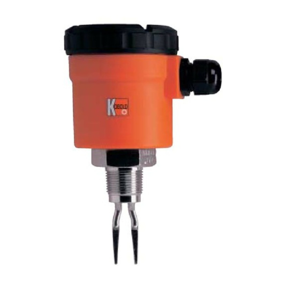
- Page 1 Operating Instructions Level Switch Tuning Fork Principal Model: NWS...
-
Page 2: Table Of Contents
Instrument Inspection ..................3 Regulation Use ....................3 Operating Principle ..................4 Use in Hazardous Areas (NWS-2E) .............. 4 Device function ..................4 Commissioning/Installation ..............5 Designation ..................5 ... -
Page 3: Note
Operating instructions 4. Regulation Use Kobold model NWS Liquid-Level Switches are designed to be wired as 2-wire or 3-wire switches and can be universally installed in any position in containers and piping. They can be used in many types of liquids including oils, water, paints and varnishes, sauces, milk, carbonated liquids and foamy oils. -
Page 4: Operating Principle
The NWS operates as a two-wire switch in series with the load. The simple electronic switch is operated by the liquid. The NWS can also be connected to a PLC through a third terminal. Special Features: The NWS has a switch status indicator with LED, which can be seen continuously through a lens in the cover. -
Page 5: Commissioning/Installation
LI value of 0,65 µH m per each meter of supplied cable should be considered. 6.3 Designation Model: NWS***2E* **** II 1 G Ex ia IIC T6 Ga BVS 03 ATEX E 119 IECEx BVS 13.0004 Identification number: 0158 Production-No.: SN: E999999 (consecutively numbered) -
Page 6: Temperature Resistance
When working on electrical and pneumatic plants, the special safety requirements shall be observed. The NWS switch can be installed in containers or piping by screwing it into a threaded mounting flange or other type of mounting device. The threaded con- nection must be sealed with Teflon (PTFE) tape. -
Page 7: Electrical Connection
Attention! Be sure that the supply voltage of your system is the same as that specified on the device nameplate. Make sure that the electrical supply lines are de-energised when connecting the device! 8.1 NWS-...200 Series wiring with a 2-wire connection Please note: ... - Page 8 "OFF" threshold voltages. If you should have problems with this set- ting, please contact us for assistance. Wiring diagram: 3-wire, V = 24 V output PNP: U ~ 20 V; U ~ 3.5 V; I ≤ 400 mA HIGH Page 8 NWS K06/0214...
-
Page 9: Nws
8.2 NWS-...23/24; NWS-...2W/2H; NWS-...2E (ATEX certification) Make sure that the electrical supply lines are de-energised. Connect the device using the M12x1 plug or a connection cable as shown in the wiring diagram below. Matching connectors with different cable lengths are optionally available. -
Page 10: Settings
The LED provides visual confirmation that the NWS is operating correctly and that the status of the wet side is correctly displayed. With its oper- ating mode switch, the NWS can be set to operate as either an N/C contact or an N/O contact. - Page 11 Hysteresis Level 1(approx. 1-1.5mm): LED flashes briefly 1x, then LED 2 seconds off. Hysteresis Level 2 (approx. 3-4.5mm, Standard): LED flashes briefly 2x, then LED 2 seconds off. Hysteresis Level 3 (approx. 5-7.5mm): LED flashes briefly 3x, then LED 2 seconds off. NWS K06/0214 Page 11...
-
Page 12: Settings For Nws
The LED provides visual confirmation that the NWS is operating correctly and that the status of the wet side is correctly displayed. With its oper- ating mode switch, the NWS can be set to operate as either an N/C contact or an N/O contact. - Page 13 9.2.2 Selecting operating mode By reversing the polarity of the power supply, the switching function of the NWS- ...23/24 can be changed from a N/C contact to a N/O contact. In the case of the NWS-...2W/2H (WHG), the switching function cannot be changed for reasons of safety.
- Page 14 The magnet supplied with the device can be used to switch off the electrical output of the NWS- independent of status of the tuning fork. In this case, the magnet must be placed on the location indicated on the device nameplate. After approximately 2 seconds, the NWS- switches the output off and the LED begins blinking.
-
Page 15: Technical Information
Max. operating pressure: 45 bar Flange connection: see pressure steps Max. medium temp.: 130 °C (NWS-..200..) 90 °C (for all other NWS) short-time 150 °C for CIP (valid for all models NWS) Min. medium density 0.8 kg/L (lower on request) Ambient temperature: -20 °C...+70 °C... - Page 16 N/C or N/O adjustable by switching polarity of supply voltage (only NWS...23/24) Overload cut-off (NWS-2x): In case of thermal overload or excessive current, the unit cust off the load. The triggering of overload protection is indicated by fast blinking of the LED.
-
Page 17: Order Codes
11. Order Codes Example: NWS-R20 20 0 0000 Connection Model Electrical connection Sensor version R ¾ male thread NWS-R20... 0060 = 60 mm (only for Plastic housing NWS-T / NWS-L / NWS-H) R 1 male thread NWS-R25...* 200 = 24...240 V ¾... -
Page 18: Recommended Spare Parts
In this case, we recommend that the device be returned to the manufacturer for servicing. 15. Disposal Disposal of packaging and used parts shall be done in conformance with the regulations of the country in which the device is installed. Page 18 NWS K06/0214... -
Page 19: Dimensions
16. Dimensions NWS-...200 24...V AC/DC Plastic housing NWS-...23S/24S NWS-...23F/24F NWS-...2WS/2HS NWS-...2WF/2HF 24 V 24 V Plug connection Terminal connection Ø 40 Ø 40 NWS-...2ES NWS-...2EF ATEX ATEX Plug connection Cable connection NWS K06/0214 Page 19... - Page 20 DN 25 /PN 40 approx. 47 DN 50 / PN 40 approx. 95 ANSI 1“ 300 lbs 17,5 approx. 41 ANSI 2“ 300 lbs 22,4 approx. 92 NWS-L.. NWS-H.. Sanitary connection Aseptic connection (DIN 11851) (DIN 11864) Page 20 NWS K06/0214...
-
Page 21: Declaration Of Conformance
17. Declaration of Conformance We, KOBOLD Messring GmbH, Hofheim-Ts, Germany, declare under our sole responsibility that the product: Level Switch model: NWS -.. to which this declaration relates is in conformity with the standards noted below: EN 61010-1 Safety requirements for electrical equipment for... -
Page 22: Supplement To The Ec-Type Examination Certificate
18. Supplement to the EC-Type Examination certificate Page 22 NWS K06/0214... - Page 23 NWS K06/0214 Page 23...
- Page 24 Page 24 NWS K06/0214...
-
Page 25: Iecex Certificate
19. IECEx Certificate NWS K06/0214 Page 25...
Need help?
Do you have a question about the NWS and is the answer not in the manual?
Questions and answers