Table of Contents
Advertisement
Advertisement
Table of Contents

Related Manuals for ONOSOKKI TS-3200A


Summary of Contents for ONOSOKKI TS-3200A
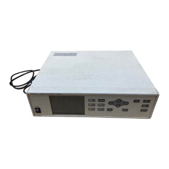
- Page 1 TS - 3200A DIGITAL TORQUE METER INSTRUCTION MANUAL ONO SOKKI CO., LTD.
- Page 2 Warranty 1. This product is covered by a warranty for a period of one year from the date of purchase. 2. This warranty covers free-of-charge repair for defects judged to be the responsibility of the manufacturer, i.e., defects occurred while the product is used under normal operating conditions according to descriptions in this manual and notices on the unit label.
- Page 3 To ensure that you get the most out of your new Digital Torque Meter, we recommend that you read and follow the instructions in this document carefully. The TS-3200A Digital Torque Meter was severely checked for normal operation before shipment. When you unpack the unit, make sure that it has not been damaged during transportation, and then check operation according to this document.
- Page 4 FOR YOUR SAFETY Please read this manual including this section to ensure safe and proper use of your TS- 3200A Digital Torque Meter. ONO SOKKI, Ltd. bears no responsibility for any warranty regarding damages, failures, or injury resulting from failure to follow directions in this manual during operation. Meaning of Symbols In this document and this section, precautions are classified into two categories: WARNING and CAUTION...
-
Page 5: Before Using
BEFORE USING • Use the instrument with the specified voltage. The standard voltage is 100 to 240VAC (no selection required). Use of power other than that specified may cause damage to the instru- ment. Before turning the power ON, make sure that the power meets the specified voltage. WARNING •... - Page 6 PRECAUTIONS ON ELECTRIC SHOCK • Never cut the internal or external ground wire of a product or disconnect the wire connected to the protective ground terminal of the instrument because doing so may cause electric shock or damage to the instrument. WARNING •...
- Page 7 ABOUT PROTECTIVE GROUNDING • Be sure to ground the instrument for safety and noise elimination. The grounding method is shown below. WARNING • Grounding with a three-pronged power plug. Plug the supplied three-pronged AC power cord into a three-pronged outlet. IF A PROBLEM OCCURS •...
- Page 8 ABOUT INSTALLATION AND CONNECTIONS • Do not install the instrument in unstable locations. If the instrument should fall it may cause injury or damage to equipment. CAUTION • Do not place large or heavy objects on top of the instrument. If an object on top of the instrument should fall it may cause injury or damage to equipment.
- Page 9 MEASUREMENT • Do not connect or disconnect input cables during measurement because there is a risk of failure of external devices. CAUTION • Do not turn the power OFF during measurement because there is a risk of failure of external devices.
-
Page 10: Table Of Contents
CONTENTS Chapter 1 Overview Overview ........................1-2 Block Diagram ....................... 1-3 System Configuration ....................1-6 Checking Accessories ....................1-7 Precautions on Wiring of Torque Meter ..............1-8 Chapter 2 Before Use Name and Function of Each Section ................2-2 2.1.1 Front Panel ......................... 2-2 2.1.2 Rear Panel ........................... - Page 11 4.4.1 Displaying MAX, MIN, P-P , and RIPPLE ................4-9 Taking Absolute Values of Measured Data ............... 4-10 Synchronous Operation ..................... 4-13 Checking Settings ......................4-14 Calibrating Analog Output ..................4-15 Self-Check ........................4-16 4.9.1 Description of Items ......................4-17 4.10 Initializing Settings ...................... 4-19 4.11 Turning LCD Off ......................
- Page 12 5.6.8 Analog Output Settings ....................5-40 5.6.9 Comparator (CMP Comparison) (Effective When TS-0322 Is Installed) ................5-41 5.6.10 Measurement Commands ....................5-42 5.6.11 Check Commands ......................5-44 5.6.12 Backup Commands ......................5-45 5.6.13 Bus Commands (Applied Only to GP-IB) ................ 5-45 Adding One Analog Output Channel TS-0328 ............
-
Page 13: Chapter 1 Overview
Chapter 1 Overview 1.1 Overview 1.2 Block Diagram 1.3 System Configuration 1.4 Checking Accessories 1.5 Precautions on Wiring of Torque Meter... - Page 14 Since the TS-3200A measures the torque and rpm at the same time and is provided with an analog output as standard, remote function, etc., it can be used to control external load devices.
-
Page 15: Block Diagram
1. Overview 1.2 Block Diagram SIG 1 Data processing unit Torque signal SIG 2 LCD display SIG OUT Rotational signal INT REVO (3 input signals selectable) Analog converter unit REVO1 (MP-910) AC signal REVO2 DC signal (Encoder MP981) conversion SIG 1 Common to COM SIG 1 conversion... - Page 16 • Torque counters Since the TS-3200A has a short sampling time, it is provided with two torque counters: one counts the pulse train which is proportional to the phase difference and the other counts the pulse train with a fixed phase difference (360 degrees) to obtain T1 and T2, respectively.
- Page 17 1. Overview • Analog converter unit The result of high-speed operation is output by the D/A converter in analog form. The conversion factor of digital value and analog value is determined by CAPACITY. The full-scale voltage output is 10V. • LCD display Displays torque (TORQUE), rotation (REVO), or output (POWER) which is selected, as well as each parameter setting.
-
Page 18: System Configuration
1.3 System Configuration Output Torque detector Data analysis MD Series Recording device For small capacity X-Y recorder Plot of torque speed characteristics SS Series Pen recorder Standard type Sequential plot of measured data Electromagnetic oscillograph Sequential plot of momentary changes DSTP Series Heavy duty type Data recorder... -
Page 19: Checking Accessories
1. Overview Checking Accessories When unpacking the unit, make sure that you have all the following accessories. Name Quantity Remark Model 1.9 m AC power cable AX-203 REMOTE connector R03-PB8M Instruction manual AC power cable REMOTE connector Instruction manual... -
Page 20: Precautions On Wiring Of Torque Meter
Precautions on Wiring of Torque Meter In recent years, increasing number of test devices using or measuring inverters have been used. An inverter emits noise because of the operating principle and may affect other devices near it. Torque meters are not an exception. The degree of effect depends on the amount of noise generation, installation condition of signal lines, device installation condition, distance between the inverter and device, and other factors. -
Page 21: Chapter 2 Before Use
Chapter 2 Before Use 2.1 Name and Function of Each Section 2.2 Detector Connections... -
Page 22: Name And Function Of Each Section
ENTER CW/CCW ON/OFF LOCAL 1 Power switch Turns the power of the TS-3200A ON or OFF. When the power is ON, the LED lights up in green. 2 LCD display Displays measured data and parameter settings. 3 MEAS DISP key Selects the measurement screen. - Page 23 2. Before Use 6 MENU key Selects the parameter setting screen. 7 OPTION key Displays mounted options collectively. 8 CAL key Selects the calibration screen of the analog output. 9 Cursor key key, Move the cursor to a target item within the setting display. key, Increments/decrements numeric values when entering condition settings.
-
Page 24: Rear Panel
2.1.2 Rear Panel TORQUE REVO ANALOG OUT SIG 1 REVO 1 REVO 2 REMOTE SIG 2 P-OUT AC INPUT 100∼240 V 50 / 60 Hz 35 VA MAX T 2 A ONO SOKKI CO., LTD. MADE IN JAPAN * In pin arrangement, COM is an abbreviation of common and NC is an abbreviation of "Not connected." Y TORQUE SIG Torque detector signal input/output connector Connector: TRC116-23A10-7F (Tajimi Electronics) - Page 25 2. Before Use U REVO Connectors for rotary encoder signal input. The signal can be input to either of the follow- ing two connectors. • REVO1 Applicable connector: C02 type (BNC) • REVO2 Connector: R03-R6F Applicable connector: R03-PB6M (Tajimi Electronics) REVO REVO 1 REVO 2...
- Page 26 O REMOTE Connector for external control signal input/output. Connector: R03-R8F Applicable connector: R03-PB8M (Tajimi Electronics) REMOTE Pin arrangement CLR IN TRIG IN Input C CCW/CCW selection Input common READY OUT COM for the above Output TRIG OUT COM for the above AC INPUT 100~240 V P AC LINE...
- Page 27 2. Before Use S BCD output (option) Connector: 57-40500 (DDK) Applicable connector: 57-30500(DDK) Amphenol full-pitch, 50 pins For the connector table, refer to 5.3, "BCD Output TS-0323." D Comparator output (option) Connector: RM12BRB-6P (Hirose Electric) Applicable connector: RM12BPG-6S (Hirose Electric) Pin arrangement CMP OUT1 CMP OUT2...
-
Page 28: Detector Connections
2.2 Detector Connections The TS-3200A and detectors are connected with the specified torque cable ands the rotational cables. Rotary encoder (MP-910) Torque detector TRC116-12A10-7M connector Rotary encoder (MP-981) TORQUE REVO ANALOG OUT SIG 1 REVO 1 REVO 2 REMOTE SIG 2... -
Page 29: Chapter 3 Basic Operations
Chapter 3 Basic Operations 3.1 Sequence of Basic Operations 3.2 Setting Parameters of Torque Detector 3.3 Selecting Rotational Direction (CW/CCW) 3.4 Zero Adjustment 3.5 Setting Frequency Characteristic N-0 Compensation Values of Detector 3.6 Setting Parameters of Rotary Encoder 3.7 Setting Output (POWER) Operational Conditions 3.8 Setting Measurement Display 3.9 Setting Analog Output... -
Page 30: Sequence Of Basic Operations
3.1 Sequence of Basic Operations • Leave the load side of the Connect the TS-3200A and a torque detector using the signal cable. detector uncoupled. • Rotate the upper motor Turn ON the power of the torque detector and the TS-3200A. -
Page 31: Basic Key Operations
3. Basic Operations 3.1.1 Basic Key Operations In the following explanation, direct switches on the front panel are enclosed in [ ] and soft menus of the LCD display in ( Moves the cursor to the left. Moves the cursor upwards. Moves the cursor downward. -
Page 32: Setting Parameters Of Torque Detector
3.2 Setting Parameters of Torque Detector Enter parameters (specific values) of the torque detector. Enter the numeric values of FACTOR, CAPACITY, and PULSE inscribed on the name plate of the torque detector. The unit specified by UNIT of item CAPACITY becomes the unit for the measurement display. However, numeric values containing a decimal point cannot be entered as items CAPACITY and FACTOR. - Page 33 3. Basic Operations • UNIT (unit) The unit specified here becomes the unit for the measurement display. (For selection of the unit, refer to 4.12, "Torque Unit Conversion." 1: mNm 2: Nm 3: kNm • DIGIT (the number of digits of the measurement display) The number of display digits of the measurement display (including decimal places) is 4 or 5.
- Page 34 Operating Procedure Example: In case of torque detector SS-050 CAPACITY FACTOR 8086 PULSE 120P/R DIGIT 4 digits Note: For numeric values containing the decimal point, take the unit (mNm/Nm/kNm) into consideration to convert the value into an integer before entering. (1) Press the [MENU] key.
- Page 35 3. Basic Operations (3) Select (TORQUE) using the keys and then press the [ENTER] key. The following screen appears. Setting Capacity (4) Select (CAPACITY) using the keys and then press the [ENTER] key. (5) 1 Enter the capacity. Enter +0005 using the , and keys and then press the [ENTER] key.
- Page 36 Setting Factor (6) Select (FACTOR) using the , and keys and then press the [ENTER] key. Press the [ENTER] key to move the cursor to a numeric unit. (7) Enter 8086 as FACTOR using the , and keys and then press the [ENTER] key. When you press the [ENTER] key, the setting is established and then the cursor moves to (FACTOR).
- Page 37 3. Basic Operations Setting Torque Detector Type (11) Select (TYPE) using the key and then press the [ENTER] key. 0: SS/DD/DSTP/MD ..Torque measurement can be performed from the stationary condition (rpm 0). 1: DP ........Torque measurement cannot be performed in the stationary condition. This parameter is reflected in the torque measurement ready state.
-
Page 38: Selecting Rotational Direction (Cw/Ccw)
3.3 Selecting Rotational Direction (CW/CCW) It is necessary to select CW/CCW of the TS-3200A and torque detector according to the rotational direction under measurement. The TS-3200A is provided with the following two different methods: Using a panel switch of the TS-3200A to select CW/CCW... -
Page 39: Cw/Ccw
3. Basic Operations 3.3.1 CW/CCW ONO SOKKI uses CW/CCW to represent the rotational direction of the shaft of the torque detector. When the shaft rotates clockwise When the shaft rotates when viewed from the torque counterclockwise when viewed from detector drive side the torque detector drive side Set this switch to the upward position. -
Page 40: Selecting Cw/Ccw Using A Panel Switch
3.3.2 Selecting CW/CCW Using a Panel Switch CW/CCW can be changed using a panel switch of the TS-3200A. Change the switch of the torque detector according to the rotational direction. Operating Procedure (1) Press the [MENU] key. The following screen appears. - Page 41 3. Basic Operations (3) Select (TORQUE) using the keys and then press the [ENTER] key. The following screen appears. (4) Select (ROTATION) using the keys and then press the [ENTER] key. (5) Select 1:INT using the keys and then press the [ENTER] key. (6) Press and hold the [CW/CCW] key for 2 seconds or longer.
-
Page 42: Selecting Cw/Ccw Using Remote Function
3.3.3 Selecting CW/CCW Using REMOTE Function When the REMOTE function is used, CW/CCW can be selected using an external sequence. Change the switch of the torque detector according to the rotational direction. Operating Procedure (1) Press the [MENU] key. (2) Select (DETECTOR SET) and then press the [ENTER] key. (3) Select (TORQUE) using the keys and then press the [ENTER] key. -
Page 43: Zero Adjustment
Stop shaft rotation of the torque detector and rotate only the upper motor in the no-load condition. Zero adjustment refers to correction of the torque indication of the TS-3200A in this case. Zero adjustment is not achieved only by connecting the torque signal cable. -
Page 44: Automatic Zero Value Setting
Make sure the rotational direction (CW or CCW) under measurement, then change over the upper motor of the torque detector and the TS-3200A according to the rotational direction. When using a detector which does not use the upper motor, such as the DP type, rotate the drive shaft (no-load condition) and then make this setting when it is rotating at 100r/min or or higher speed. - Page 45 3. Basic Operations AUTO (automatic) Setting (4) Select MODE. The default value is 1: AUTO. Press the [ENTER] key. When you press the [ENTER] key, the torque zero compensation value is determined automatically. MANU (manual operation) Setting (5) 1 Select MODE. Select 2:MANU using the keys and then press the [ENTER] key.
-
Page 46: Setting Frequency Characteristic N-0 Compensation Values Of Detector
Setting Frequency Characteristic N-0 Compensation Values of Detector Despite shaft rotation in the no-load condition, a number may be displayed in the torque display depending on the frequency characteristic of the detector and display, and the friction torque of the detector. -
Page 47: Manual Setting Of N-0 Compensation Values
3. Basic Operations 3.5.1 Manual Setting of N-0 Compensation Values Example: Setting N-0 compensation value for the CW direction Prepare the following table, rotate the detection shaft using a motor, etc., then record the torque display value for each rpm. Note: Like zero compensation, enter display values, with the decimal point removed, in the count column. - Page 48 Operating Procedure (1) Press the [MENU] key. The following screen appears. (2) Select (DETECTOR SET) and then press the [ENTER] key. The following screen appears. (3) Select (TORQUE) using the keys and then press the [ENTER] key. The following screen appears. 3-20...
- Page 49 3. Basic Operations (4) Select (N-0 CW) or (N-0 CCW) using the keys and then press the [ENTER] key. The following screen appears. (5)1Select (ON/OFF). (N-0 compensation) Select 1:ON or 2:OFF using the keys and then press the [ENTER] key. Press the [ENTER] key to move the cursor to 2.
-
Page 50: Automatic Setting Of N-0 Compensation Values
3.5.2 Automatic Setting of N-0 Compensation Values N-0 compensation values are set while increasing the rotating speed of the torque detector from zero to the rpm specified as CAPACITY. In order to minimize the influence of the inertia of the object under measurement, a sufficiently long time (about 30 seconds) shall be taken as the time from zero to the maximum rpm (specified as CAPACITY). - Page 51 3. Basic Operations If the time for rpm to increase from 0 to CAPACITY is short disturbing normal sampling of compensation data or if the rpm has not reached CAPACITY, the following error message appears. DATA NOT ENOUGH If the maximum rpm is not reached, reduce CAPACITY and then perform N-0 compensation. To set the opposite direction, perform the operation in 3.3, "Selecting Rotational Direction (CW/CCW)", select (4) N-0 CCW, then perform the same operation.
-
Page 52: Setting Parameters Of Rotary Encoder
3.6 Setting Parameters of Rotary Encoder Enter measurement conditions for the rotary encoder. Operating Procedure I Default Settings The default settings at the time of shipment are shown below. They depend on measurement conditions for the rotary encoder. CAPACITY 10000 UNIT r/min 1 r/min... - Page 53 3. Basic Operations • CAPACITY The value specified here becomes the full-scale value of the analog output. The position of the decimal point of the display changes according to the input value of CAPACITY. • Input range 10 to 99999 Decimal point position of measurement display Minimum input value of LOW Input value of CAPACITY...
- Page 54 • POINT Although the decimal point position of the REVO (rpm) display is specified by CAPACITY, it can be changed. However, only such setting that decreases the number of significant decimal places can be made. • OFFSET It is possible to offset the measurement value of REVO (rpm). Measured value = Actual rpm - OFFSET value With manual setting, press the [ENTER] key, enter a numeric values using the , and...
- Page 55 3. Basic Operations I Number of Pulses for Rotary Encoding The number of pulses specified for rotary encoding depends on the type of the torque detector and the rotary encoding method. Check the type of the torque detector used and then select the applicable number of pulses from the following description.
-
Page 56: When Rpm Is Not Detected Directly From Rotating Shaft (Input Of Ratio)
3.6.1 When Rpm Is Not Detected Directly from Rotating Shaft (Input of RATIO) When putting a gear, etc. between the shaft to which the rotary encoder is attached and the output shaft, as shown below, to decrease or increase the output speed (rotary encoding is not possible on the output shaft side), the gear ratio is set as RATIO. -
Page 57: Operating Procedure
3. Basic Operations Operating Procedure (1) Press the [MENU] key. (2) Select (DETECTOR SET) and then press the [ENTER] key. (3) Select (REVO) and then press the [ENTER] key. The following screen appears. (4) Select (RATIO) using the keys and then press the [ENTER] key. Press the [ENTER] key to move the cursor to the numerator of +0001/0001. -
Page 58: Setting Output (Power) Operational Conditions
3.7 Setting Output (POWER) Operational Conditions Enter operational conditions for POWER (output) from the torque and rpm measurement ranges (CAPACITY). Output (W) = 2π x Torque (N-m) x Rotational speed (r/s) 2π Output (W) = x Torque (N-m) x Rotational speed (r/min) PS = 0.7355kW CAPACITY specified here becomes the analog full-scale value. - Page 59 3. Basic Operations Operating Procedure (1) Press the [MENU] key. The following screen appears. (2) Select (DETECTOR SET) and then press the [ENTER] key. The following screen appears. (3) Select (POWER) using the keys and then press the [ENTER] key. The following screen appears.
-
Page 60: Setting Measurement Display
3.8 Setting Measurement Display The measurement display enables four different display formats. Select and set any desired measurement items. Operating Procedure (1) Press the [MENU] key. (2) Select (USER SET) and then press the [ENTER] key. The following screen appears. (3) Select (DISPLAY) using the keys and then press the [ENTER] key. - Page 61 3. Basic Operations • DISP: Display format setting Images for display formats are shown below. Select 0 to 3 using the , and keys and then press the [ENTER] key. 0: Normal 1: Triple 2: Main&Sub 3: All 0: Normal 1: Triple 2: Main&Sub 3: All...
- Page 62 • ITEM Select the display item from the following: 0: Torque 1: Revo 2: Power • AVE TIME: Data average time setting for measurement of MAX, MIN, P-P, RIPPLE Setting range 0.004s to 10.000s Refer to 4.4, "MAX, MIN, P-P, and RIPPLE of Display Data" for details. •...
-
Page 63: Setting Analog Output
3. Basic Operations 3.9 Setting Analog Output Any two out of torque, rotation, and POWER (output) can be output to ANALOG OUT 1 and 2 on the rear panel. These output terminals are isolated from the torque input section and the chassis of the TS- 3200A. - Page 64 • Time constant Step torque or rpm Analog output 100% t=0 4ms 4ms Sampling time Fig. 1 Fig. 2 Operation time When a step torque signal is applied to the torque detector as shown above, the analog output changes as shown in Fig.
- Page 65 3. Basic Operations Operating Procedure (1) Press the [MENU] key. The following screen appears. (2) Select (USER SET) and then press the [ENTER] key. The following screen appears. (3) Select (ANALOG OUT) and then press the [ENTER] key. The following screen appears. 3-37...
- Page 66 1 ITEM Select the item to be output. 0: TORQUE 1: REVO 2: POWER 2 SCALE Set the full-scale value in 0.01V steps. 0.01 to 10.00V 3 τ τ τ τ τ Set a time constant. 4 ABS Set this setting to ON for output with absolute value. Note: If you do not press the [ENTER] key in step 4, the measured data in steps 1 to 4 are not updated.
-
Page 67: Other Operations
Chapter 4 Other Operations Using REMOTE Function Selecting Detector Parameter Settings LOCK Function MAX, MIN, P-P , and RIPPLE of Display Data Taking Absolute Values of Measured Data Synchronous Operation Checking Settings Calibrating Analog Output Self-Check 4.10 Initializing Settings 4.11 Turning LCD Off 4.12 Torque Unit Conversion 4.13 Temperature Compensation for FAC- TOR of Torque Detector... -
Page 68: Using Remote Function
Data is changed when the input to TRIG IN changes from contact open to close (from the Hi to Lo logic). Input interval: 100ms to 32s External device TS-3200A input +5 V 10kΩ At the time of dry contact input or logic input 100Ω... -
Page 69: Output (Dry Contact Output)
Display and BCD are switched between at the timing indicated by ↓. READY output The contact closes in the measurement mode. When using the output of the TS-3200A as a feedback signal for control, etc., use the READY output for safety to apply interlocking. -
Page 70: Pin Arrangement
I Recommended Interface TS-3200A output External device +30V or less 10 kΩ +5 V Common Load voltage 30VDC or less Load current 100mA or less ON resistance 10Ω or less OFF resistance 500kΩ or higher 4.1.3 Pin Arrangement Connector: R03-R8F... -
Page 71: Selecting Detector Parameter Settings
4. Other Operations 4.2 Selecting Detector Parameter Settings With the TS-3200A, it is possible to set up to 10 different parameter settings of the detector, etc. as condition files. Since comment entry is possible for each condition file, this function is effective when using multiple detectors by selecting each one. -
Page 72: Lock Function
4.3 LOCK Function Of the direct key switches on the front panel, this function locks (disables) only the [CW/CCW] and [TRQ ZERO] switches which may cause failure if switched during measurement. Each time you press the [LOCK] switch, the switches are locked or unlocked. When locked, character LOCK is highlighted. -
Page 73: Max, Min, P-P , And Ripple Of Display Data
4. Other Operations 4.4 MAX, MIN, P-P , and RIPPLE of Display Data (1) Press the [MENU] key. (2) Select (USER SET) and then press the [ENTER] key. (3) Select (DISPLAY) using the keys and then press the [ENTER] key. The following screen appears. - Page 74 Data average time MODE is applied to the MAX, MIN, P-P, and RIPPLE data. TS-3200A are sampling data at 4ms intervals. The MAX, MIN, P-P, and RIPPLE data are extracted from the 4-ms interval sample data averaged by the specified time.
-
Page 75: Displaying Max, Min, P-P , And Ripple
4. Other Operations 4.4.1 Displaying MAX, MIN, P-P , and RIPPLE MAX, MIN, P-P The previous data is reset at TRIG IN and the MAX, MIN, and P-P values up to the next TRIG IN are displayed. RIPPLE Percent display is made from the P-P value and average value between TRIG IN and the next TRIG IN based on the operational expression. -
Page 76: Taking Absolute Values Of Measured Data
4.5 Taking Absolute Values of Measured Data Absolute values can be taken independently for LCD display, analog output, and comparator data. Torque measurement values have the polarity: positive (+) torque and negative (-) torque. This function is effective to know the absolute value regardless of the polarity of torque and to apply interlocking with excessive torque regardless of the polarity. - Page 77 4. Other Operations Operating Procedure In Case of DISPLAY (1) Press the [MENU] key. (2) Select (USER SET) and then press the [ENTER] key. (3) Select (DISPLAY) using the keys and then press the [ENTER] key. The following screen appears. (4) Select items (MAIN1) to (SUB4) for absolute value setting using the keys to set an absolute value and then press the [ENTER] key to move the cursor.
- Page 78 In Case of Analog Output Steps (1) and (2) are the same as those in "In Case of DISPLAY display." (3) Select (ANALOG OUT) using the keys and then press the [ENTER] key. The following screen appears. (4) Select CH1 and CH2 using the keys and then press the [ENTER] key to move the cursor.
-
Page 79: Synchronous Operation
The slave TS-3200A synchronizes with the TRIG OUT timing output by the master TS-3200A. The gate time of the slave TS-3200A equals the time period between TRIG IN and next TRIG IN. Connections are shown below. GATE selection for display (DISPLAY) is performed in the DISPLAY setting screen. -
Page 80: Checking Settings
4.7 Checking Settings It is possible to check detector parameter settings DETECTOR SET and USER SET collectively. Press the [SETVIEW] key on the front panel. Overall settings can be checked by scrolling the screen using the keys. 4-14... -
Page 81: Calibrating Analog Output
4.8 Calibrating Analog Output The TS-3200A has been calibrated before shipment. If you calibrate the TS-3200A, be sure to use a voltmeter with an accuracy of ±0.02% or higher. Note: During CAL operation, the measurement ready state turns OFF. There are two different methods for the [CAL] function. - Page 82 Operating Procedure When EXT CALIBRATION Is Displayed (1) Press the [CAL] key. The following screen appears. (2) Using the keys, select (EXT CALIBRATION) and then press the [ENTER] key. The following screen appears. When you select 0: ZERO and then press the [ENTER] key, 0V voltage is output. When you select 1: SPAN and then press the [ENTER] key, 10V voltage is output.
- Page 83 1 Select (CH2) using the keys and then press the [ENTER] key. Perform the same operations as steps 2 to 5 for CH1. To adjust and check the scale of the recorder connected to the TS-3200A, select only 0:ZERO/1:SPAN. 4-17...
-
Page 84: Self-Check
4.9 Self-Check The following describes the procedure to check the basic functions of the TS-3200A. Operating Procedure (1) Press the [MENU] key. (2) Select (USER SET) and then press the [ENTER] key. (3) Select (TEST MODE) and then press the [ENTER] key. -
Page 85: Description Of Items
4. Other Operations 4.9.1 Description of Items • ROM TEST Displays the current version of the CPU execution program. • RAM TEST Checks whether the built-in work RAM is normal. When there is no problem, "OK" is displayed. • LCD TEST Inverts dots of the LCD display to check whether there is any missing dot. - Page 86 • I/0 TEST Checks the contact input function and contact output function. Contact input: Performed by short-circuiting the item-related pin of each connector. Contact output: Connect a continuity tester and a device to the item-related pin of each connector. Select each item to turn the output ON or OFF forcibly. •...
-
Page 87: Initializing Settings
4. Other Operations 4.10 Initializing Settings If the TS-3200A hangs up because of defective settings, it is necessary to initialize the backup memory with the following procedure. 1 Initializing the entire backup memory Turn the power ON while holding down the [TRIG] and [ESC] keys. -
Page 88: Turning Lcd Off
4.11.1 Turning Off Since the back light of the LCD display has a life, it is recommended that you turn off the LCD display when you do not need to see it. Digital Torque Meter TS-3200A MEAS MENU DISP OPTION... -
Page 89: Adjusting Contrast
4. Other Operations 4.11.2 Adjusting Contrast Adjustment of the LCD contrast is possible. Operating Procedure (1) Press the [MENU] key. (2) Select (USER SET) and then press the [ENTER] key. (3) Select (TEST MODE) using the keys and then press the [ENTER] key. The following screen appears. -
Page 90: Torque Unit Conversion
4.12 Torque Unit Conversion The unit of torque display is determined by [DETECTOR]. If you want to measure torque using a different unit from the one inscribed on the detector, change FACTOR and CAPACITY according to the conversion expression. Notes: •... -
Page 91: Converting Unit System From Kgf To N
4. Other Operations 4.12.1 Converting Unit System from kgf to N When using a torque detector with the kgf unit system purchased before, it is necessary to convert the value of FACTOR and CAPACITY. However, unit system conversion from kgf to N is possible only for detectors with a CAPACITY inscription of 10 gfcm or more. -
Page 92: Temperature Compensation For Factor Of Torque Detector
4.13 Temperature Compensation for FACTOR of Torque Detector With phase difference torque detectors from ONO SOKKI, the material of the torsion bar at the detecting section has temperature characteristics. Since temperature characteristics affect FACTOR, temperature compensation after measurement is not required if you have performed measurement using the corrected FACTOR. - Page 93 4. Other Operations (4) Select (FACTOR) using the keys and then press the [ENTER] key. The following screen appears. (5) Move the cursor to CORR=OFF using the key and then press the [ENTER] key. The following screen appears. • ON/OFF 0:OFF Temperature compensation not provided 1:ON...
-
Page 94: Default Settings
4.14 Default Settings I DETECTOR SET TORQUE I t e m Default value CAPACITY UNIT DIGIT FACTOR 8 0 0 0 CORR ROTATION I n t ZERO CW 10000 ZERO CCW 10000 N-0 CW R1 to 10=0 T1 to 10=0 N-0 CCW R1 to 10=0 T1 to 10=0... - Page 95 4. Other Operations I USER SET Display DISP NORMAL GATE INT AVE TIME 0.250s ITEM MODE GATE MAIN1 Torque MAIN2 Revo MAIN3 Power SUB1 Torque SUB2 Torque SUB3 Torque SUB4 Torque RIPPLE Time constant Analog Out ITEM Scale (τ) Torque 10.0V 250ms Revo...
- Page 96 4-30...
-
Page 97: Chapter 5 Options
Chapter 5 Options 5.1 Analog Output High-Speed Response (1ms) TS-0321 5.2 Comparator TS-0322 5.3 BDC Output TS-0323 5.4 RS-232C Interface 5.5 GP-IB Interface 5.6 Communication Commands (RS-232C/GP-IB/LAN) 5.7 Adding One Analog Output Channel TS-0328... - Page 98 The TS-3200A has a standard time constant of 16ms to 64s for the analog output. When the TS-0321A option is built in the TS-3200A, 4ms or 1ms can be selected as the sampling time. When 1ms sampling time is selected, the analog output is updated at 1ms sampling intervals allowing high-speed response.
- Page 99 5. Options Operating Procedure (1) Press the [MENU] key. The following screen appears. (2) Select (USER SET) and then press the [ENTER] key. The following screen appears. (3) Select (OPTION) and then press the [ENTER] key. The following screen appears.
- Page 100 (4) Select (HIGH RESPONSE TS-0321:INSTALLED) and then press the [ENTER] key. The following screen appears. (5) Select 0:4ms or 1:1ms using the keys and then press the [ENTER] key. When the TS-0321 option is mounted and 0:4ms is selected, 0:OFF is added as a time constant setting for selection.
- Page 101 5. Options 5.2 Comparator TS-0322A This option incorporates the comparison setting function allowing 2-channel comparison setting. It can be used to control torque, rpm, and output (POWER). It compares the measured value with a setting and makes contact output. I Default Settings CMP 1 CMP 2 CMP 3...
-
Page 102: Description Of Functions
5.2.1 Description of Functions • CH1/CH2/CH3/CH4 The comparator function can be performed for 4 channels. • ITEM Select a comparison item. 0: TORQUE Torque 1: REVO R p m 2: POWER Output • SET1, SET2 Enter a comparison setting. • MODE Select the comparison mode. - Page 103 5. Options • AVE TIME The average time setting is 0.004 to 10.000s. The average time cannot be set in 0.001s steps because of the relationship with internal sampling. Although any time can be specified, this setting is converted to a neighbor value which can be processed internally when you press the [ENTER] key.
-
Page 104: Description Of Mode
5.2.2 Description of MODE I AVE (0.004 to 10.000s) The sectional average measured value for each average time setting is compared with the comparator setting. When the average measured value exceeds the comparison measured data, the contact output is made. Example: REVO 1000 r/min r/min •... - Page 105 5. Options I EXT The average measured value from the TRIG IN signal to the next TRIG IN signal is compared with the comparator setting. When the average measured value exceeds the comparator setting, contact output is made. r/min • TRIG IN signal Comparator setting 1000r/min CMP OUT...
-
Page 106: Setting Procedure
5.2.3 Setting Procedure Operating Procedure (1) Press the [MENU] key. (2) Select (USER SET) and then press the [ENTER] key. (3) and (OPTION) are selected and then press the [ENTER] key. The following screen appears. (4) Select (COMPARATOR TS-0322:INSTALLED) using the keys and then press the [ENTER] key. - Page 107 5. Options (5) Select (ITEM), (SET), (MODE), (AVE TIME), and (H/L) using the keys and then press the [ENTER] key. 1 Select (CH1 and CH2) or (CH3 and CH4) using the keys and then press the [ENTER] key. 2 Select a comparison item of (ITEM) using the keys and then press the [ENTER] key.
-
Page 108: Recommended Interfaces
30VDC or less Load power supply 100mA or less ON resistance 10Ω or less OFF resistance 500kΩ or higher The following interface circuit is recommended. External device TS-3200A output Pulled up with 10kΩ. CMP-1a, 2a 3a, 4a CMOS or TTL 5-12... -
Page 109: Bcd Output Ts-0323
5. Options 5.3 BCD Output TS-0323 The BCD output and DAV command output of the TS-3200A are all open-collector outputs. The following explains signals as logic recognized by the external device assuming that the BCD output and DAV command are connected to the external device through the recommended interface. - Page 110 HOLD IN Ch2 data 4 x 10 N.C. Ch2 data 8 x 10 BCD DAV (updating data) Ch2 data 1 x 10 N.C., unused pins, are used inside the TS-3200A. Do not use them for relaying or other purposes. 5-14...
- Page 111 5. Options Operating Procedure (1) Press the [MENU] key. (2) Select (USER SET) and then press the [ENTER] key. (3) Select (OPTION) and then press the [ENTER] key. The following screen appears. (4) Select (BCD OUT TS-0323:INSTALLED) and then press the [ENTER] key. The following screen appears.
- Page 112 • MODE Select the comparison mode. 0: GATE INT Updates the output for each time specified by GATE INT of DISPLAY. Data is the sectional average in the time setting. 1: GATE EXT Updates the output using the TRIG key on the front panel or the TRIG IN signal of the REMOTE function.
-
Page 113: Recommended Interface
5. Options 5.3.2 Recommended Interface The following interface circuit is recommended. BCD output / polarity output / DAV (updating data) External device TS-3200A output Pulled up with 10kΩ. BCD-OUT CMOS or TTL Output format Open-collector 74LS07 Withstand voltage 24 V max... -
Page 114: Timing Chart
Since the pulse width of the DAV command output is as short as about 5µs, it cannot be read by the general-purpose I/O port of the sequencer. When reading the BCD data and polarity, be sure to perform hold input using the sequencer. TS-3200A Sequencer, etc. Data output, polarity output... - Page 115 5. Options G When hold input is used 1 s, 10 s, or TRIG IN input Measurement data Hold input Hold state Data output, polarity output 4 ms MAX 20μs MAX Print command output About 100 to 150μs Busy input 4 ms MAX Print operation Printing...
-
Page 116: Rs-232C Interface
5.4.1 Overview The RS-232C is a serial communication interface standardized by Electronic Industries Association (EIA). The RS-232C interface of the TS-3200A enables data read-out, N-0 compensation value write, and other operations using appropriate programs for minicomputers and personal computers. 5.4.2 Specifications Standard: Conforms to EIA and JISX5101. -
Page 117: Connection With Pc
5. Options 5.4.3 Connection with PC Cable connection Connection with PC is made with a cross cable. Use a cable which can be connected normally referencing the pin arrangement of the TS-3200A. Cable connection Basic connection TS-3200A side PC side N.C. - Page 118 Operating Procedure (1) Press the [MENU] key. (2) Select (USER SET) and then press the [ENTER] key. (3) Select (OPTION) and then press the [ENTER] key. The following screen appears. (4) Select (RS-232CTS-0325:INSTALLED) using the keys and then press the [ENTER] key.
-
Page 119: Check Procedure At Hyper Terminal
5.4.4 Check Procedure at Hyper Terminal Hyper Terminal, an accessory of Windows, make it easier to check communication. Prepare an RS-232C cable and connect the personal computer and the TS-3200A using it. Start WindowsXX. Select Start, Programs, Accessories, then Hyper Terminal. - Page 120 10. Press [ASCII Setup] to open the ASCII setting window and then make the following setting. [ASCII Sending] Check the following items: Send line ends with line feeds Echo typed characters locally [ASCII Receiving] Check the following items: Append line feeds to incoming line ends Wrap lines that exceed terminal width Then, press OK.
-
Page 121: Gp-Ib Interface
The GP-IB interface built in the TS-3200A makes it possible to specify the panel and receive data through programming operation on a minicomputer or a personal computer. -
Page 122: Precautions Before Use
Check whether the command type agrees with the program sequence. For example, if you send a command for data read and then another one to the TS-3200A, the TS-3200A waits until it is specified as a talker resulting in program lock. -
Page 123: Gp-Ib Specifications
5. Options 5.5.3 GP-IB Specifications Full length of cables 20m or less (total length of all cables) Length of one cable 5m or less (only connection between devices) Maximum number of devices connected 15 or less (including one controller) Signal lines For the GP-IB interface, dedicated 24-pin connectors are used. - Page 124 Operation of each signal line DIO1-8 (data lines) Used for general data (including 8-bit parallel and address bus commands), etc. DAV (Data Valid) Indicates that the data on DIO is valid. NRFD (Not Ready For Data) Indicates that the listener can receive the data on DIO. NDAC (Not Data Accepted) Indicates that the listener has received the data on DIO.
-
Page 125: Gp-Ib Interface Functions
Talker is canceled when UNT (Untalk) is received from a controller. If bus command transmission from the controller to the TS-3200A is not possible depending on the preceding or following command flow, the GP-IB bus may hang up (bus lock). Therefore, the interface functions are not always effective. - Page 126 UN TALK X1011111 Cancels a talker. GROUP EXECUTE TRIGGER X0001000 Applies trigger. 1: LLLLL Listener dress 2: TTTTT Talker address Note: The DC function (device clear function) of the TS-3200A only initializes this interface at the same time as IFC. 5-30...
-
Page 127: Gp-Ib Address Settings
5. Options 5.5.5 GP-IB Address Settings Operating Procedure (1) Press the [MENU] key. (2) Select (USER SET) and then press the [ENTER] key. (3) Select (OPTION) and then press the [ENTER] key. (4) Select (GP-IBTS-0326:INSTALLED) using the keys and then press the [ENTER] key. -
Page 128: Communication Commands (Rs-232C/Gp-Ib/Lan)
( ) is not necessary. 5.6.1 Parameter Settings With the TS-3200A, 10 different parameter settings can be registered with file formats CONDITION1-10. First, the CONDITION number (1-10) setting is selected. Then, various parameters are set for the selected CONDITION. -
Page 129: Display Mode
5. Options 5.6.2 Display Mode LDM(d) LCD display mode selection (DISP) d = 0:NORMAL 1:TRIPLE 2:MAIN&SUB 3:ALL LDSn(d, m, g, a) LCD display selection Display position Item n= 1:MAIN1 d= 0:TORQUE 2:MAIN2 1:REVO 3:MAIN3 2:POWER 4:SUB1 3:OFF (Display OFF) 5:SUB2 6:SUB3 7:SUB4 Display mode... -
Page 130: Measurement Commands
5.6.3 Measurement Commands RLDn LCD display data read (ASCII) (Reads LCD display value.) This command outputs data in the following formats: When OFF, 0 is returned. Returns measured value only when LCD display is made. n= 1: MAIN1 2:MAIN2 3:MAIN3 4:SUB1 5:SUB2 6:SUB3... -
Page 131: Bcd Output (Effective When Ts-0323 Is Installed)
5. Options 5.6.4 BCD Output (Effective When TS-0323 Is Installed) BCDc(,d) BCD output item setting c= Channel 1 or 2 d= 0:TORQUE 1:REVO 2:POWER 3:OFF BCGc(,d) BCD output data update mode setting c = Channel 1 or 2 d = 0:GATE INT (internal gate) 1:GATE EXT(TRIG IN) 2:SAMPLE (usually 4ms / 1ms for high-speed option) BCTc(,d) -
Page 132: Torque Settings
5.6.5 Torque Settings DTR(d) Torque detector rotation d = 0:EXT 1:INTCW 2:INTCCW DTZn(d) Torque detector zero n = 0:CW 1:CCW d = 0 to 99999 - Auto Zero when 1. DTF(d) Torque detector factor d = 1 to 65535 DTC(d) Torque detector capacity d = ±1-9999 TTU(d) - Page 133 5. Options DTD(d) Number of digits of torque detector (DIGIT) d = 4:4 digits 5:5 digits Increase in the number of digits does not result in improved torque measurement accuracy. DTP(d) Number of teeth of torque detector d = 1 to 9999 DTNn (,r,t) Torque detector N-0 n = 0:CW...
-
Page 134: Rpm Settings
DRPn(d) Number of teeth of rotary encoder Since the number of teeth of the TS-3200A is 1, n is not necessary for the TS- 3200A. With the TS-3600B/TS-3110B, set n = 0-2. When the TS-3200A receives this command, it sets only the number of teeth, d. Be sure to supply a comma (,). -
Page 135: Output (Power) Settings
5. Options 5.6.7 Output (POWER) Settings DFC(d) Output capacity d = ±1-99999 DFU(d) Output unit d = 0:mW 2:kW 3:PS 4: – – Invalid even if received by TS-3200A. 5-39... -
Page 136: Analog Output Settings
= 0.1 to 10.00 [V] Output full scale setting DABc(,d) D/A output method If the TS-3200A receives only VOLTAGE, it ignores this command. c = 1 to the number of channels mounted d = 0:VOLTAGE(0-10V) 1 or greater is ignored. -
Page 137: Comparator (Cmp Comparison)
5. Options 5.6.9 Comparator (CMP Comparison) (Effective When TS-0322 Is Installed) CPSc(,d) Comparator source c = 1 or 2 (1:1 and 2 Channel, 2:3 and 4 Channel) d = 0:TORQUE 1:REVO 2:POWER 3:ON 4:OFF CPDc(,d) Comparator data c = Channel 1, 2, 3 or 4 d = 0 to ±99999 CPTc(,d) Comparator average time... -
Page 138: Measurement Commands
Read display data Successive commands for the TS-3600B/TS-3100B Since the TS-3200A allows 7-row display, when this command is received, data for the items set in main display 1 to 2 are returned. With this command, data is output in the following format: +XX.XXX... - Page 139 5. Options Read external I/O interface status CMP OUT2 CMP OUT1 READY ROTATION TRG OUT TRG IN CLR IN SMS(m) Service request mask setting (applied only to GPIB) By setting the bit of the corresponding interruption factor to 1 (unmask) or 0 (mark), it is possible to generate interruption for any desired interruption factors.
-
Page 140: Check Commands
5.6.11 Check Commands TSTn Performs self test. (The settings differ from the TS-3600B). n = 0: Displays the ROM TEST version. 1:RAM TEST 2:LCD TEST 3:KEY TEST 4:I/O TEST 5:BCD TEST Outputs a service request at the end. ICSn1n2n3[,d] Analog output calibration If the option in [ ] is omitted, only the status is changed but calibration is not performed. -
Page 141: Backup Commands
Performs the same function as IFC. The GP-IB interface is initialized to the condition when the power is turned ON. Since this command is an addressed command, only the TS-3200A can be cleared out of multiple devices connected to the GP-IB line. -
Page 142: Adding One Analog Output Channel Ts-0328
5.7 Adding One Analog Output Channel TS-0328 5.7.1 Overview One analog output channel of the TS-3200A is added. Calibration and other setup can be performed with the same procedures as for CH1 and CH2. 5.7.2 Setup Procedures CH3 is added to the analog output setup as follows: For setup items, refer to 3.9, "Setting Analog Output"... -
Page 143: Chapter 6 Menus
Chapter 6 Menus 6.1 [MENU] Key 6.2 [CAL] Key 6.3 [TRQ ZERO] Key... -
Page 144: Menu] Key
6.1 [MENU] Key DETECTOR SET COND ..........4.2 Selecting Detector Parameter Settings COMMENT ..........4.2 Selecting Detector Parameter Settings TORQUE ..........3.2 Setting Parameters of Torque Detector CAPACITY CAPACITY UNIT 1:mNm 2:Nm 3:kNm DIGIT FACTOR FACTOR CORR ..4.13 Temperature Compensation for FACTOR of Torque Detector ON/OFF 0:OFF... - Page 145 6. Menus DETECTOR SET REVO ..........3.6 Setting Parameters of Rotary Encoder CAPACITY CAPACITY UNIT 0:r/min 1:r/s 2:Hz SIGNAL 0:Int Revo 1:Revo1 2:Revo2(Single) 3:Revo2(Double) RATIO ..3.6.1 When Rpm Is Not Detected Directly from Rotating Shaft (Input of RATIO) POINT 1:0.1 2:0.00 3:0.000...
- Page 146 USER SET DISPLAY ... 3.8 Setting Measurement Display, 4.4 MAX, MIN, P-P , and RIPPLE of Display Data DISP GATE INT AVE TIME MAIN1-MAIN3 SUB1-SUB4 ITEM 0:TORQUE 1:REVO 2:POWER 3:OFF MODE 0:NOR 1:MAX 1:MIN 2:P-P 3:RIPPLE GATE 0:INT 1:EXT 0:OFF 1:ON ........
- Page 147 6. Menus USER SET ........... Chapter 5, "Options" OPTION ..5.1 Analog Output High-Speed Response (1ms) TS-0321A HIGH RESPONSE 0:OFF 1:16ms ..5.2 Comparator TS-0322A COMPARATOR CH1, CH2 ITEM 0:TORQUE 1:REVO 2:POWER MODE 0:AVE 1:PEAK 2:EXT AVE TIME 0:OFF 1:ON H/L1 (Logic of CH1) 0:HI 1:LO 2:ON 3:OFF...
- Page 148 6. Menus USER SET OPTION BCD OUT ......5.3 BCD Output TS-0323 ITEM 0: TORQUE 1:REVO 2:POWER 3:OFF MODE 0: GATE INT 1:GATE EXT 2:SAMPLE τ Effective only when MODE is 2:SAMPLE. 0:OFF 1:16ms 2:31ms 3:63ms 4:125ms 5:250ms 6:500ms 7:1s 8: 2s 9:4s A:16d C:32s D:64s 0:ON 1:OFF RS-232C ......
-
Page 149: Cal] Key
6.2 [CAL] Key EXT CALIBRATION 0:ZERO 1:SPAN INT CALIBRATION 0:ZERO 1:SPAN 0:ZERO 1:SPAN (Option) 0:ZERO 1:SPAN 6.3 [TRQ ZERO] Key TRQ ZERO MODE 1:AUTO 2:MANU 3:CLR CW ZERO CCW ZERO... -
Page 151: Chapter 7 Troubleshooting
Chapter 7 Troubleshooting... - Page 152 Troubleshooting If you think of a failure, check the following points first. If the TS-3200A does not operate normally after check, contact your dealer or ONO SOKKI sales office nearby. S y m p t o m Cause Check point...
- Page 153 7. Troubleshooting S y m p t o m Cause Check point Solution Remarks No rpm Incorrect DETECTOR Is SIGNAL selection Select SIGNAL 3.6 "Setting setting in DETECTOR according to the Parameters of Rotary settings correct ? connected detector. Encoder" Mismatched rpm display Incorrect DETECTOR Are DETECTOR...
-
Page 155: Chapter 8 Specifications
Chapter 8 Specifications The following specifications apply to a single unit of the TS-3200A. Since the overall accuracy is determined in combination with the detector, also check the accuracy of the detector used. -
Page 156: Torque Signal Measurement Unit
Torque Signal Measurement Unit Input Section Amplifier Isolated unbalanced DC amplification Input signal Phase difference conversion type detector output signal Input impedance About 2kΩ (with an input signal amplitude of 2Vpp or less) Input frequency range 200Hz to 50kHz Input signal amplitude range 0.2Vpp to 15Vpp Connector TRC116-23A10-7F (Tajimi Electronics) - Page 157 8. Specifications Output Section Analog output format Voltage output 0±10V/F.S Scale Attenuation setting of the full scale is possible from 0.1V to 10V in 0.1V steps. Response 16ms to 64s depending on the time constant setting OFF is provided only when the TS-0321 option is mounted. Accuracy When combined with the detector (with 1s average value) ±0.2% / full-scale...
-
Page 158: Rotational Signal Measurement Unit
Rotational Signal Measurement Unit Input Section I Sine Wave of REVO1 MP910, etc. Amplifier AC amplification Input impedance 10kΩ or higher Input frequency range 10Hz to 100kHz Input signal amplitude range 0.2Vrms to 45Vrms Connector I Square Wave of REVO2 MP981, etc. Amplifier Unbalanced DC amplification Input impedance... - Page 159 8. Specifications Setup Section Signal selection REVO1 (MP910), REVO2 (MP981), INTSIG (torque detector SIG2) Capacity 1 to 99999 (limited by the number of teeth of the detector and ratio setting) Unit r/min, r/s, Hz Rpm corresponding to 1Hz input frequency ≤ Setting < Capacity Minimum measurement rpm setting Number of teeth of detector 1 to 99999 P/R...
-
Page 160: Power (Output) Measurement Unit
POWER (Output) Measurement Unit Input Section Calculated from the measured torque and rpm (basic expression) Output (W) = 2π / 60 x Torque (Nm) x Rpm (r/min) PS = 0.7355kW Setup Section Capacity 1 to 99999 Unit mW, W, kW, PS Response Time constant setting 16ms/31ms/63ms/125ms/250ms/500ms/1s/2s/4s/8s/16s/32s/64s... -
Page 161: Display Panel
8. Specifications Display Panel Display Section I LCD Specifications Full dot-matrix type LCD panel Dot color: White Background color: Black 320x240 dots Back light for the above panel LCD back light ON/OFF function provided LCD contrast Adjustment function provided I Display Contents Main display 1 to 3 step display can be selected. -
Page 162: Interface Unit
Synchronous operation of multiple TS-3200A is possible using the trigger input and trigger output. Ready output Contact output When the TS-3200A is in the torque measurement mode, the contact closes. I Signal Formats Input section In case of non-voltage contact input Open voltage: 5.25V or less... -
Page 163: Analog Output
8. Specifications Analog Output Channel 2 channels Items Two items out of torque, rpm, and POWER (output) can be selected. For details, refer to the following: 8.1 Torque Signal Measurement Unit: Output Section 8.2 Rotational Signal Measurement Unit: Output Section 8.3 POWER (Output) Measurement Unit: Output Section Connector C02 (BNC) - Page 164 I RS-232C Standard Conforms to EIA and JISX5101. Communication mode Start-stop transmission, full-duplex mode Transmission rate (bps) 1200/2400/4800/9600/19200 Character length 8 bits Parity check None Stop bit Terminator CR+LF Connector D-Sub 9-pin male I GP-IB Electrical / mechanical specifications IEEE488-1978 Function specifications SH1/AH1/T6/L4/SR1/RL1/PP0/DC1/DT1/C0 Support bus commands...
-
Page 165: General Specifications
8. Specifications General Specifications ±10% Power voltage 100-240VAC 50/60Hz Power consumption 70VA (100VAC) or less Insulation resistance 10MΩ or higher (test voltage 500VDC) Withstand voltage 1500VAC, 1 minute Operating temperature range 0 to 40°C Storage temperature range -10 to 55°C Outside dimensions 360(W) x 99(H) x 301(D) (projections not included) Weight... -
Page 166: Outside Dimensions
Outside Dimensions I UA0002 Specifications Panel-mount fitting Digital Torque Meter TS-3200A MEAS MENU TRIG LOCK DISP OPTION VIEW ZERO POWER ENTER CW/CCW ON/OFF LOCAL ( 10 ) This device complies with Part 15 of the FCC Rules. Operation is subject to the following two Conditions: (1) This device may not cause harmful interference, and (2) this device must accept any interference received, including interference that may cause undesired operation. - Page 167 8. Specifications ( 6 ) ( 4.2 ) ( 12 ) 4-M5 Panel cutout dimensions 8-13...
- Page 168 I UA0001 Specifications Panel-mount fitting Digital Torque Meter TS-3200A MEAS TRIG MENU LOCK DISP OPTION VIEW ZERO POWER ENTER CW/CCW ON/OFF LOCAL ( 10 ) TORQUE REVO ANALOG OUT SIG 1 REVO 1 REVO 2 REMOTE SIG 2 P-OUT AC INPUT 100∼240 V...
- Page 169 8. Specifications ( 6 ) ( 4.2 ) ( 12 ) 8-15...
- Page 170 8-16...
- Page 171 *Outer appearance and specifications are subject to change without prior notice. HOME PAGE: http://www.onosokki.co.jp/English/english.htm WORLDWIDE ONO SOKKI CO., LTD. 3-9-3 Shin-Yokohama, Kohoku-ku, Yokohama 222-8507, Japan Phone : +81-45-476-9712 : +81-45-470-7244 E-mail : overseas@onosokki.co.jp B00002125 / IM08111202(1.2) 107(MS)001...
Need help?
Do you have a question about the TS-3200A and is the answer not in the manual?
Questions and answers